1. Overview of the Adaptive Acceleration/Deceleration Function
Function description: When the adaptive acceleration/deceleration enable is turned on, the motor can be protected, preventing excessive torque during motor motion.
Applicable scope: Only supports four-axis SCARA robots.
Setting path: Settings → Human-Machine Collaboration → Adaptive Acceleration/Deceleration
According to the load 3D drawing provided by the design personnel, find the corresponding data and enter the load mass, load inertia and center of mass in each direction.
2. Parameter Setting Screen
> 2.1 Enable Switch
- Function: The master switch of the adaptive acceleration/deceleration function
- Description: After filling in the corresponding parameters, the function takes effect when the enable switch is turned on
> 2.2 Joint Mass Parameters
The joint mass parameters are used to describe the mass characteristics of the connecting links of each robot joint.
| Parameter | Description |
|---|---|
| Joint 1 mass | The link of the robot from axis 1 to axis 2, position a1 in the figure |
| Joint 2 mass | The link of the robot from axis 2 to axis 3, position a2 in the figure |
| Joint 4 mass | The mass of the lead screw for the robot's up/down motion |
| Unit | kg |
Reference diagram:
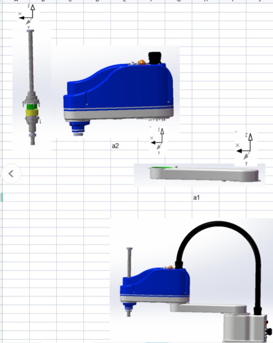
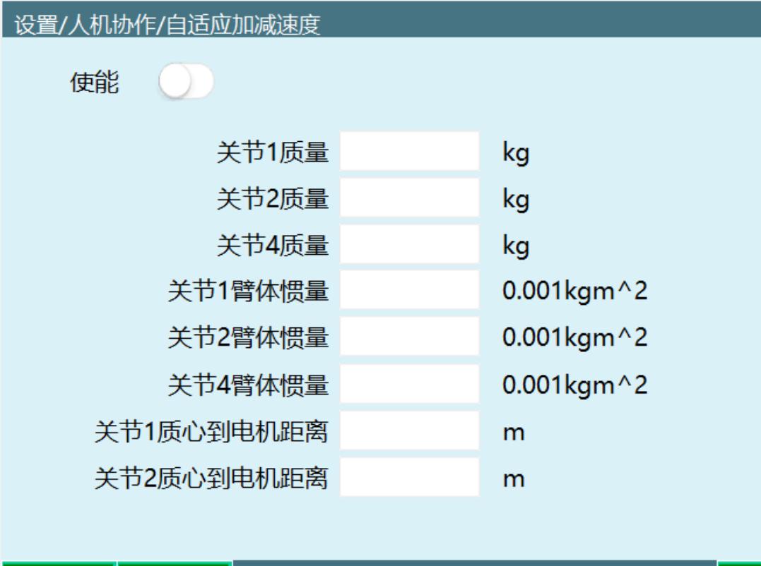
Figure 1

Joint 1 mass (position a1)
    ↓
Robot axis 1 ──────→ Axis 2
                    ↓
                Joint 2 mass (position a2)
> 2.3 Joint Arm Body Inertia
The reference frame of the arm body inertia and the distance from the center of mass to the motor of each joint is shown in the figure below.
| Parameter | Description |
|---|---|
| Joint 1 arm body inertia | The moment of inertia of the joint 1 link |
| Joint 2 arm body inertia | The moment of inertia of the joint 2 link |
| Joint 4 arm body inertia | The moment of inertia of the joint 4 lead screw |
| Unit | 0.001kgm² |
Reference frame:
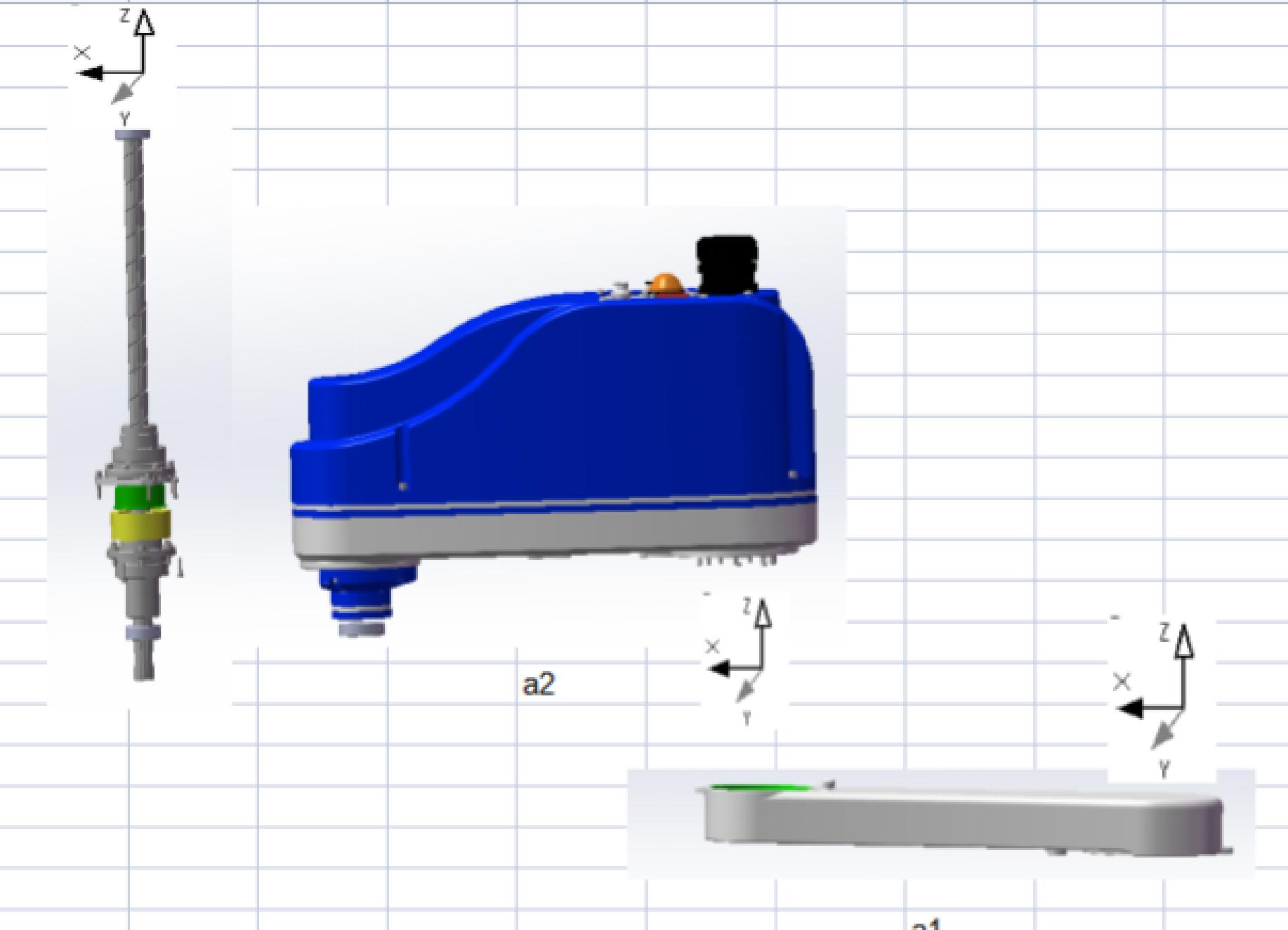
Position a2 diagram
> 2.4 Distance from Joint Center of Mass to Motor
The distance from the center of mass of each joint to the motor is used to describe the effect of mass distribution on inertia.
| Parameter | Description |
|---|---|
| Joint 1 center-of-mass-to-motor distance | The distance from the joint 1 center of mass to the drive motor |
| Joint 2 center-of-mass-to-motor distance | The distance from the joint 2 center of mass to the drive motor |
| Joint 4 center-of-mass-to-motor distance | The distance from the joint 4 center of mass to the drive motor |
| Unit | m |
> 2.5 Threshold Parameters
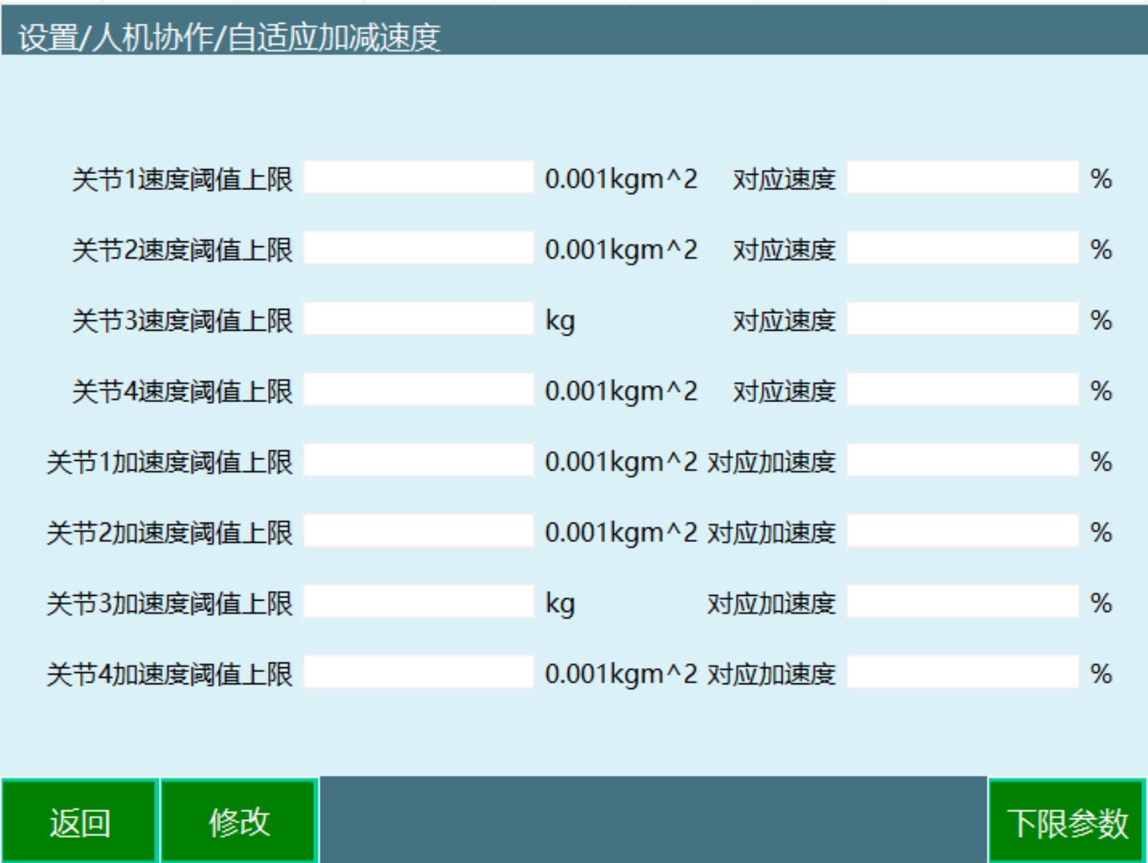
The threshold parameters are divided into: upper threshold and lower threshold. The upper threshold and the first axis are used as an example below.
2.5.1 Speed Threshold Parameters
Figure 3: Speed Threshold - Speed Relationship Curve
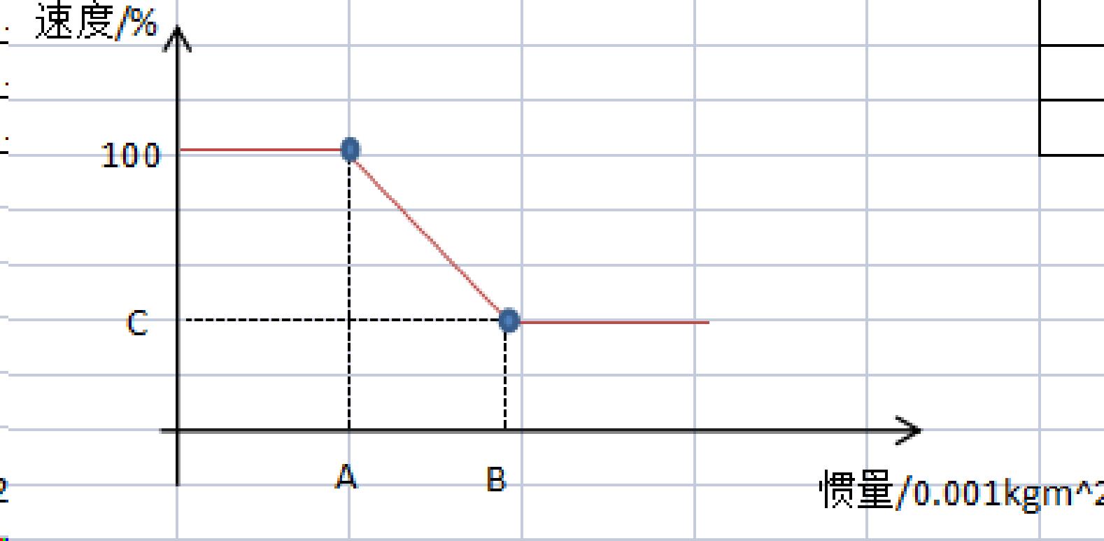
Meaning of the labels in the figure:
| Label | Description |
|---|---|
| B in Figure 3 | Speed threshold upper limit |
| 100 in Figure 3 | The speed value corresponding to A in Figure 3 |
| A in Figure 3 | Speed threshold lower limit |
| C in Figure 3 | The speed value corresponding to B in Figure 3 |
Speed threshold parameter description:
| Parameter | Description |
|---|---|
| Joint 1 speed threshold upper limit (%) | The upper threshold of the joint 1 speed |
| Speed corresponding to 0.001kgm² (%) | The speed value corresponding to an inertia of 0.001kgm² |
| Joint 2 speed threshold upper limit (%) | The upper threshold of the joint 2 speed |
| Speed corresponding to 0.001kgm² (%) | The speed value corresponding to an inertia of 0.001kgm² |
| Joint 3 speed threshold upper limit (%) | The upper threshold of the joint 3 speed |
| Corresponding speed (%) | The speed value corresponding to the inertia value (unit: kg) |
| Joint 4 speed threshold upper limit (%) | The upper threshold of the joint 4 speed |
| Speed corresponding to 0.001kgm² (%) | The speed value corresponding to an inertia of 0.001kgm² |
2.5.2 Acceleration Threshold Parameters
Figure 4: Acceleration Threshold - Acceleration Relationship Curve
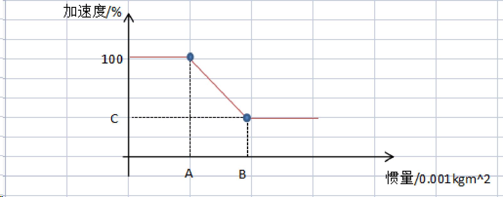
Meaning of the labels in the figure:
| Label | Description |
|---|---|
| B in Figure 4 | Acceleration threshold upper limit |
| 100 in Figure 4 | The speed value corresponding to A in Figure 4 |
| A in Figure 4 | Acceleration threshold lower limit |
| C in Figure 4 | The speed value corresponding to B in Figure 4 |
Acceleration threshold parameter description:
| Parameter | Description |
|---|---|
| Joint 1 acceleration threshold upper limit (%) | The upper threshold of the joint 1 acceleration |
| Acceleration corresponding to 0.001kgm² (%) | The acceleration value corresponding to an inertia of 0.001kgm² |
| Joint 2 acceleration threshold upper limit (%) | The upper threshold of the joint 2 acceleration |
| Acceleration corresponding to 0.001kgm² (%) | The acceleration value corresponding to an inertia of 0.001kgm² |
| Joint 3 acceleration threshold upper limit (%) | The upper threshold of the joint 3 acceleration |
| Corresponding acceleration (%) | The acceleration value corresponding to the inertia value (unit: kg) |
| Joint 4 acceleration threshold upper limit (%) | The upper threshold of the joint 4 acceleration |
| Acceleration corresponding to 0.001kgm² (%) | The acceleration value corresponding to an inertia of 0.001kgm² |
Lower limit parameter settings: The screen provides Return, Modify and Lower Limit Parameter options for configuring the lower threshold.
3. Implementation Principle
Working principle: According to the arm and load parameters, the inertia value at the start/stop position is calculated, and based on the correspondence between the inertia and the speed and acceleration parameters set above, the final speed and acceleration values during operation are determined.
Important notes:
| Precaution | Description |
|---|---|
| Horizontal coordinate of axis 3 | The horizontal coordinate of axis 3 is mass |
| Speed/acceleration limit | The corresponding speed and acceleration cannot exceed 100% |
| Inertia calculation | Comprehensively calculated based on the arm mass and load mass |
| Adaptive adjustment | The system automatically adjusts the operation parameters according to the real-time inertia |
Calculation logic:
Input parameters:
├── Arm mass parameters (joint 1/2/4 mass)
├── Arm inertia parameters (joint 1/2/4 arm body inertia)
├── Arm center-of-mass distances (joint 1/2/4 center-of-mass-to-motor distance)
├── Load mass parameters
├── Load inertia parameters
├── Load center-of-mass parameters
└── Threshold parameters (speed/acceleration upper and lower limits)

Calculation process:
1. Calculate the total inertia value at the start/stop position
2. Look up the corresponding speed and acceleration in the threshold curve based on the inertia value
3. Determine the final speed and acceleration values during operation

Output results:
├── Actual running speed
└── Actual running acceleration
4. Load Mass Settings
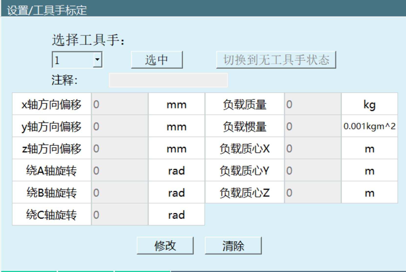
Setting path: Settings → Tool Calibration
The load mass setting screen is used to configure the physical parameters of the end load.
4.1 Load Parameter Description
| Parameter | Description | Unit |
|---|---|---|
| Select tool | Select the tool number to be set | - |
| Switch to no-tool state | Switch to the no-tool state for setting | - |
| X-axis direction offset | The offset distance of the load center of mass in the X direction | mm |
| Y-axis direction offset | The offset distance of the load center of mass in the Y direction | mm |
| Z-axis direction offset | The offset distance of the load center of mass in the Z direction | mm |
| Rotation about the A axis | The rotation angle of the load about the A axis | rad |
| Rotation about the B axis | The rotation angle of the load about the B axis | rad |
| Rotation about the C axis | The rotation angle of the load about the C axis | rad |
| Load mass | The total mass of the robot end load | kg |
| Load inertia | The moment of inertia of the load | 0.001kgm² |
| Load center of mass X | The coordinate of the load center of mass in the X direction | m |
| Load center of mass Y | The coordinate of the load center of mass in the Y direction | m |
| Load center of mass Z | The coordinate of the load center of mass in the Z direction | m |
| Comment | Description text for the load parameters | - |
4.2 Parameter Acquisition Method
Data source: According to the load 3D drawing provided by the design personnel, find the corresponding data and enter the load mass, load inertia and center of mass in each direction.
Operation steps:
- Prepare the load 3D drawing: Obtain the 3D model drawing of the load from the design personnel
- Extract physical parameters: Extract parameters such as the load mass, inertia and center-of-mass position from the 3D drawing
- Fill in the screen parameters: Fill the extracted parameters into the load mass setting screen
- Save the settings: Click the "Modify" or "Save" button to save the parameters
- Clear the settings: To clear the parameters, click the "Clear" button
4.3 Operation Button Description
| Button | Function |
|---|---|
| Select | Select the current tool number |
| Switch to no-tool state | Switch to the no-tool state |
| Modify | Enter the parameter modification state |
| Clear | Clear the currently set load parameters |
4.4 Setting Flow
Start setting
    ↓
Select the tool number
    ↓
Switch to the no-tool state
    ↓
Extract parameters from the load 3D drawing
    ↓
Fill in the load parameters:
    ├── Mass parameters (kg)
    ├── Inertia parameters (0.001kgm²)
    ├── Center-of-mass position (m)
    └── Direction offsets (mm/rad)
    ↓
Click "Modify" to save the settings
    ↓
Setting complete
4.5 Usage Precautions
| Precaution | Description |
|---|---|
| Parameter accuracy | The accuracy of the load parameters directly affects the effect of adaptive acceleration/deceleration |
| 3D drawing reference | Parameters must be extracted according to the load 3D drawing provided by the design personnel |
| Unit consistency | Pay attention to the units of each parameter to avoid parameter setting errors caused by unit mistakes |
| Parameter saving | After modifying parameters, the "Modify" or "Save" button must be clicked for the changes to take effect |
| Periodic recalibration | If the load changes, the load parameters need to be set again |
5. Q&A
Q: What is the purpose of the adaptive acceleration/deceleration function?
A: When the adaptive acceleration/deceleration enable is turned on, the motor can be protected, preventing excessive torque during motor motion. This function only supports four-axis SCARA robots.
Q: Which types of robots does the adaptive acceleration/deceleration function apply to?
A: The adaptive acceleration/deceleration function only supports four-axis SCARA robots.
Q: What is the setting path of the adaptive acceleration/deceleration function?
A: The setting path is: Settings → Human-Machine Collaboration → Adaptive Acceleration/Deceleration.
Q: What do joint 1 mass, joint 2 mass and joint 4 mass refer to respectively?
A: Joint 1 mass refers to the link mass of the robot from axis 1 to axis 2 (position a1 in the figure); joint 2 mass refers to the link mass of the robot from axis 2 to axis 3 (position a2 in the figure); joint 4 mass refers to the mass of the lead screw for the robot's up/down motion. The unit is kg for all.
Q: What is the unit of the joint arm body inertia?
A: The unit of the joint arm body inertia is 0.001kgm², including joint 1 arm body inertia, joint 2 arm body inertia and joint 4 arm body inertia.
Q: What is the unit of the distance from the joint center of mass to the motor?
A: The unit of the distance from the joint center of mass to the motor is m (meter).
Q: What two categories are the threshold parameters divided into?
A: The threshold parameters are divided into two categories: upper threshold and lower threshold.
Q: What do the speed threshold upper limit and speed threshold lower limit mean in the figure?
A: In the speed threshold - speed relationship curve: B in Figure 3 represents the speed threshold upper limit, A in Figure 3 represents the speed threshold lower limit, 100 in Figure 3 is the speed value corresponding to A in Figure 3, and C in Figure 3 is the speed value corresponding to B in Figure 3.
Q: What do the acceleration threshold upper limit and acceleration threshold lower limit mean in the figure?
A: In the acceleration threshold - acceleration relationship curve: B in Figure 4 represents the acceleration threshold upper limit, A in Figure 4 represents the acceleration threshold lower limit, 100 in Figure 4 is the speed value corresponding to A in Figure 4, and C in Figure 4 is the speed value corresponding to B in Figure 4.
Q: What is the implementation principle of adaptive acceleration/deceleration?
A: The implementation principle is to calculate the inertia value at the start/stop position according to the arm and load parameters, and determine the final speed and acceleration values during operation based on the correspondence between the inertia and the set speed and acceleration parameters.
Q: What does the horizontal coordinate of axis 3 represent? What are the limits?
A: The horizontal coordinate of axis 3 is mass, and the corresponding speed and acceleration cannot exceed 100%.
Q: What is the path for load mass settings?
A: The load mass setting path is: Settings → Tool Calibration.
Q: What do the load parameters include?
A: The load parameters include: x/y/z-axis direction offsets (unit mm), rotation about the A/B/C axes (unit rad), load mass (unit kg), load inertia (unit 0.001kgm²), load center of mass X/Y/Z (unit m) and a comment.
Q: How is the load parameter data obtained?
A: According to the load 3D drawing provided by the design personnel, find the corresponding data and enter the load mass, load inertia and center of mass in each direction.
Q: What is the unit of load mass?
A: The unit of load mass is kg.
Q: What is the unit of load inertia?
A: The unit of load inertia is 0.001kgm².
Q: What is the unit of the load center of mass?
A: The unit of the load center of mass is m (meter).
Q: What is the unit of the direction offsets?
A: The unit of the direction offsets (x/y/z-axis direction offsets) is mm (millimeter).
Q: What is the unit of the rotation about the axes?
A: The unit of the rotation about the axes (rotation about the A/B/C axes) is rad (radian).
Q: How are the load parameters saved after modification?
A: Click the "Modify" or "Save" button to save the parameters.
Q: How are the load parameter settings cleared?
A: Click the "Clear" button to clear the currently set load parameters.
Q: Under what circumstances does the adaptive acceleration/deceleration function require load parameter settings?
A: When a load is installed at the robot end, the relevant parameters need to be extracted from the load 3D drawing and set in the load mass setting screen to ensure the accuracy of the adaptive acceleration/deceleration function.
Q: What effect does the accuracy of the load parameters have on the adaptive acceleration/deceleration function?
A: The accuracy of the load parameters directly affects the effect of adaptive acceleration/deceleration. Inaccurate parameters may cause insufficient motor protection or excessive limitation.
Q: What parameters are needed to set the adaptive acceleration/deceleration function?
A: Setting the adaptive acceleration/deceleration function requires: joint mass parameters, joint arm body inertia, distance from the joint center of mass to the motor, threshold parameters (speed and acceleration upper and lower limits), load mass, load inertia, load center-of-mass position and other parameters.