Modifying Robot Points
This chapter provides detailed instructions on how to modify robot points.
How to Modify Points
Set Current Position as Target Point
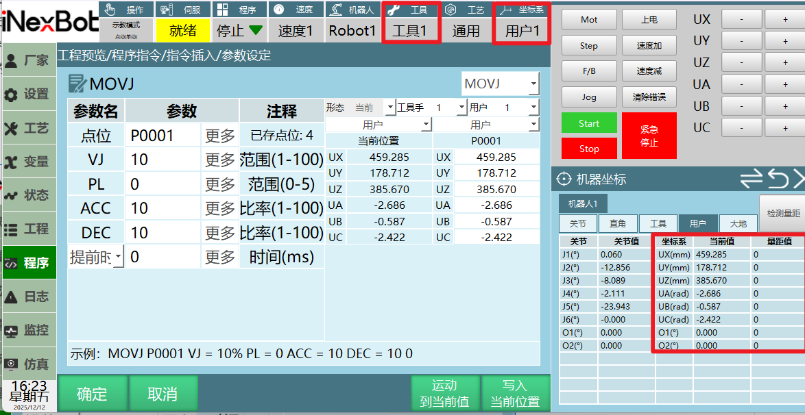
- Insert an instruction and select to create a new P variable or GP variable;
- If "New" is selected for the point, click the OK button on the parameter settings interface. After clicking OK, a new local position variable is created;
- If a GP point/P point is selected, you can directly click [Write Current Position] on the parameter settings interface;
- [Write Current Position]: Writes the robot's current tool number, current configuration, current coordinate system, and point values in the current coordinate system to the target variable;
- Click [OK], and a message bar will prompt: Variable modified successfully.
Manually Modify Target Point
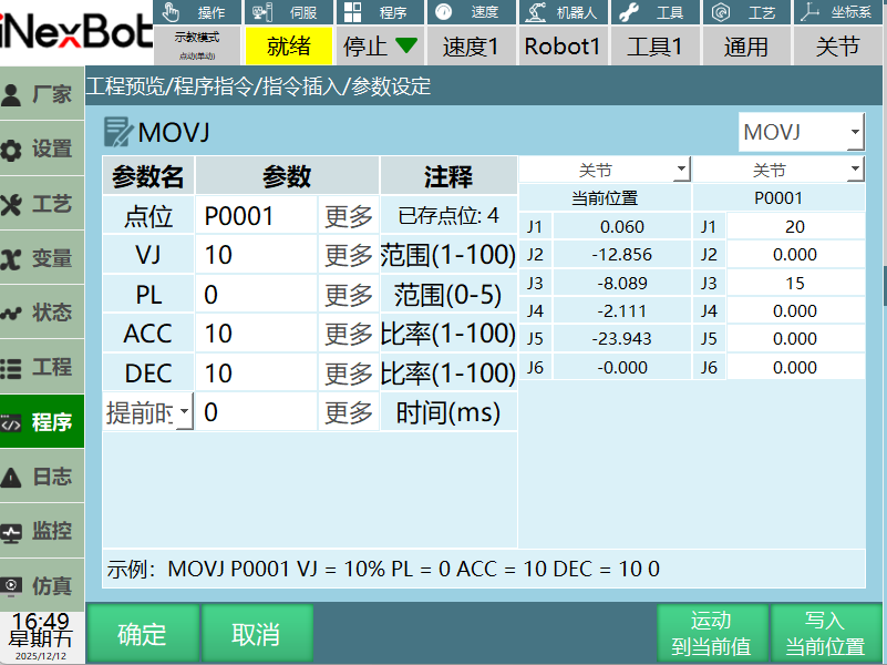
- Manually modify the robot position and target variable point values — manual modification is enabled by default;
- Enter the required coordinate values. As shown above, manually modify the first axis joint coordinate of the P0001 target variable to 20 and the third axis to 15. Click [OK] to save the modified point position to the target variable. A message bar will prompt successful modification. Click [Cancel] to return to the program page;
- [Move to Current Value]: Moves the robot to the position stored in the selected target variable. For example: if multiple motion instructions are inserted in a job file, to move to a specific point individually, select the instruction in the program instruction interface, power on and enable, then click [Move to Current Value] — the robot moves to the target point.
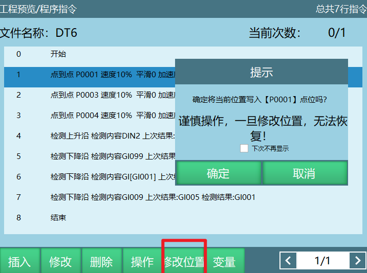
Shortcut Key [Modify Position]
- Select the instruction, click [Modify Position] — this writes the robot's current tool number, current configuration, current coordinate system, and point values in the current coordinate system to the instruction variable;
- Click [OK] to confirm the modification, or [Cancel] to discard.
Target Point Information Parameters
Configuration
Configuration range: [0,8]
- For 6-axis serial multi-joint robot models, configuration parameters exist. If "Current" is selected for the configuration parameter, the controller automatically calculates the robot's current configuration value through conversion. The configuration value is calculated from the joint positions of axes 1, 3, and 5. If the range is within [-90,+90], the value is 1; otherwise, it is 0;
- The configuration value is the binary representation of axis 1, 3, and 5 positions converted to decimal, then plus 1.
Example: A six-axis robot with axis 1 at 59°, axis 2 at 69°, axis 3 at 79°, axis 4 at 89°, axis 5 at 99°, axis 6 at 109°;
Result: Binary 110 = Decimal 6, configuration value is decimal result plus 1, so the point's configuration value is 7.
| Axis | Axis 1 | Axis 3 | Axis 5 |
|---|---|---|---|
| Binary value | 1 | 1 | 0 |
- For four-axis SCARA robot models, there is a left/right hand parameter.
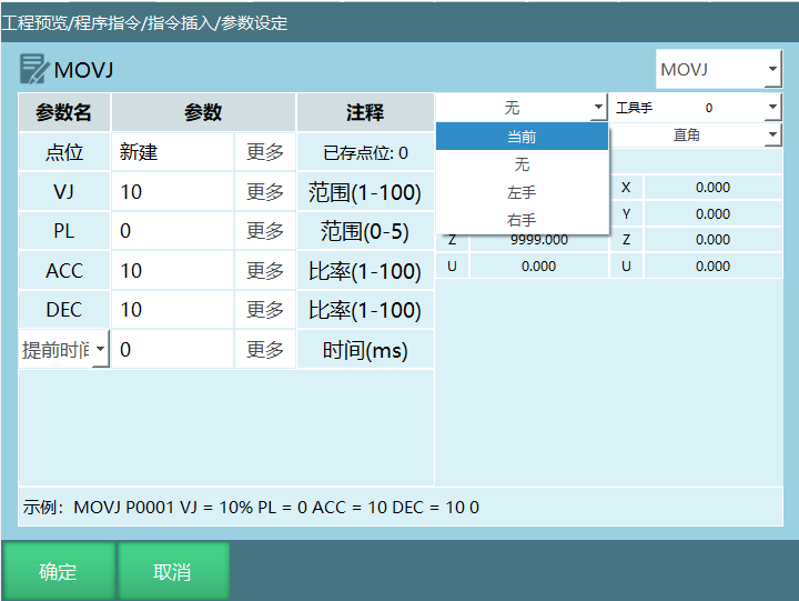
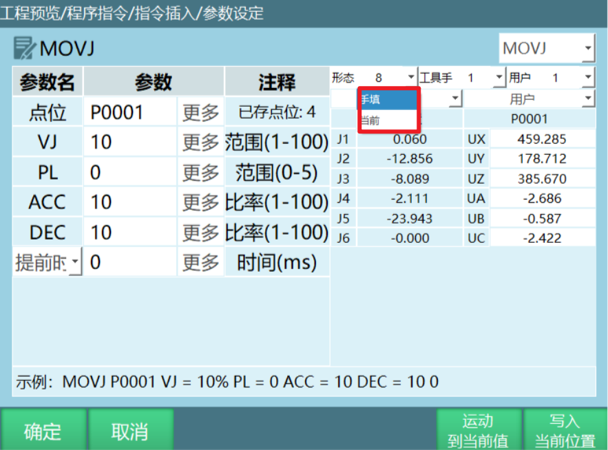
Modifying target point configuration:
- Supports manual entry and current. Manual entry: you can enter configuration values 0–8; Current: calculates a configuration value based on point information;
- After modification, click [OK] to save the configuration value.
Tool
Range: [0,999].
Modifying target point tool:
- Supports manual entry and none. Click Tool, select Manual Entry, and modify the tool number (range 1–999);
- After modification, click [OK] to save the tool change.
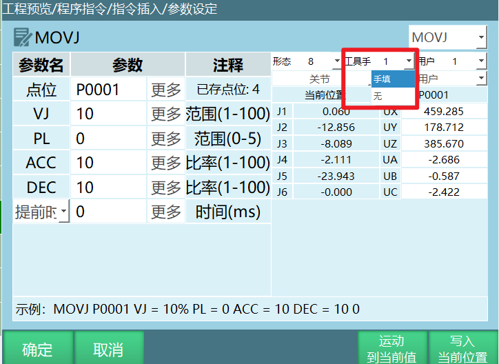
Note: When the target point's coordinates are Cartesian, tool, or user coordinates, the modified point's tool must match the actually used tool; otherwise, errors will occur during program execution!
User Coordinate
Coordinate range: [0,999]
Modifying target point user coordinate:
- Supports manual entry and none. Click Tool, select Manual Entry, and modify the tool number (range 1–999). After modification, click [OK] to save the user coordinate number.
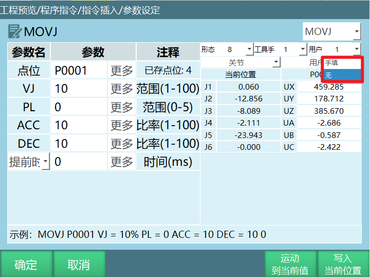
Note: When the target point's coordinates are user coordinates, the modified point's user coordinate must match the actually used user coordinate; otherwise, errors will occur during program execution!
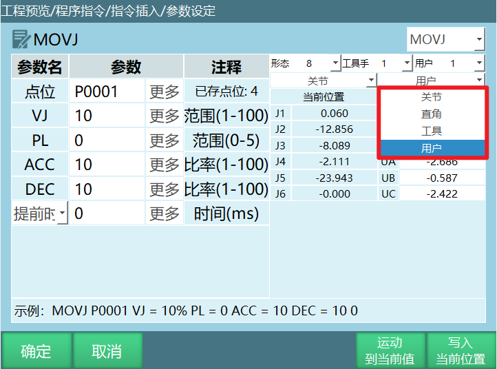
Coordinate System
- Select the coordinate system to modify. After modification, click [OK] to save.
AI Q&A for Retrieval
Q: How do I set the current position as the target point?
A: Insert an instruction and select to create a new P variable or GP variable. If "New" is selected for the point, click the OK button on the parameter settings interface. If a GP/P point is selected, directly click [Write Current Position] on the parameter settings interface, then click [OK] to complete.
Q: How do I manually modify the target point?
A: Manually modify the robot position and target variable point values, enter the required coordinate values, and click [OK] to save the modified point position to the target variable. Click [Move to Current Value] to move the robot to the position stored in the selected target variable.
Q: How do I use the shortcut key to modify position?
A: Select the instruction, click [Modify Position] — this writes the robot's current tool number, current configuration, current coordinate system, and point values to the instruction variable. Click [OK] to complete.
Q: What is the range of configuration values? How are they calculated?
A: Configuration range is [0,8]. Configuration values are calculated from the joint positions of axes 1, 3, and 5. If the range is within [-90,+90], the value is 1; otherwise, it is 0. The configuration value is the binary representation of axis 1, 3, and 5 positions converted to decimal, then plus 1.
Q: What is the range of tool numbers?
A: Tool number range is [0,999]. "0" means no tool.
Q: What is the range of user coordinate numbers?
A: User coordinate number range is [0,999]. "0" means no user coordinate.
Version History
| Version | Date | Changes | Author |
|---|---|---|---|
| 1.0.0 | 2026-06-22 | Initial version | tongmengyuan123 |