Palletizing Process
Process Introduction
Robot palletizing is mainly used in food, beverage, logistics and other industries. It is a typical application of industrial robots. With different grippers, it can achieve boxing and palletizing of finished products of various shapes in different industries. The significance of palletizing is to stack piles of items into stacks through certain patterns, making items easy to transport, unload and store.
Traditional palletizing is completed manually. This palletizing method has high labor costs and low production efficiency, and cannot meet today's automation requirements.
To improve handling efficiency and palletizing quality, save labor costs, and ensure employee safety, palletizing robots will be more widely used in production.
New Function Introduction
The palletizing interface adds process optimization. Through reference point setting and modifying configuration values, the palletizing process can be smoother.
Below is specific description:
Enter Craft/Palletizing Process/Position Debugging interface. The lower right corner adds [Additional Parameters] page. Click [Settings] to enter [Additional Parameters] page.
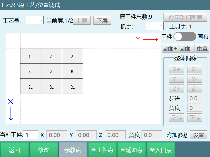
Additional Parameters page:
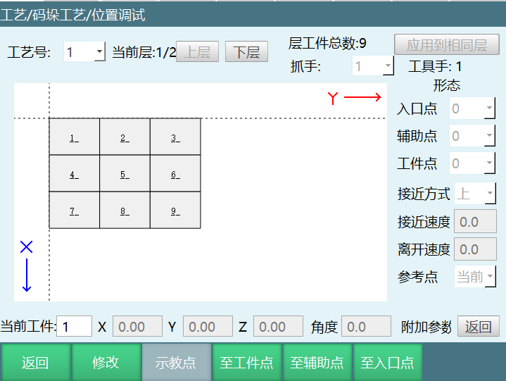
Configuration: Can set current workpiece's configuration value, including entry point, auxiliary point, workpiece point configuration. Configuration value is 0-8.
Reference Point: Can select zero position to move to target point, or move from current position to target point.
- When selecting zero, the workpiece position will be referenced based on zero position to determine if reachable. If position shows unreachable, can change configuration value. For example, if entry point shows unreachable, can modify entry point configuration value.
For example: Current craft's workpiece 9, when reference point is zero, entry point is unreachable.
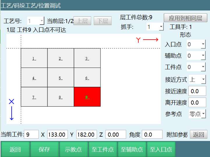
Can change workpiece 9's entry point configuration to 4. Now when reference point is zero, entry point is reachable.
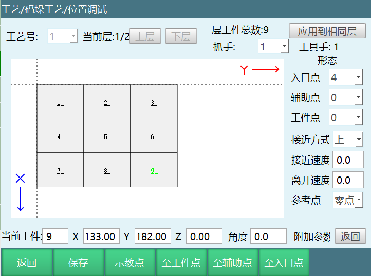
- When selecting current, the workpiece position will be referenced based on current position to determine if reachable. If position shows unreachable, can change configuration value. For example, if entry point shows unreachable, can modify entry point configuration value.
For example: Current craft's workpiece 1, when reference point is current, workpiece point, auxiliary point, and entry point are all unreachable.
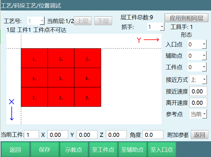
Can change workpiece 1's workpiece point, auxiliary point, and entry point configuration to 4. Now when reference point is current, workpiece position is reachable.
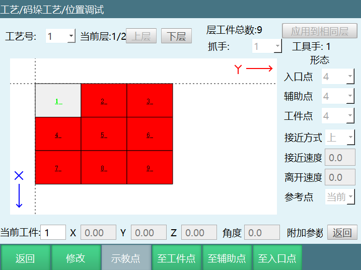
- If palletizing generated file uses joint interpolation and position unreachable error appears when running job file, can change corresponding workpiece's configuration value in position debugging/additional parameters page.
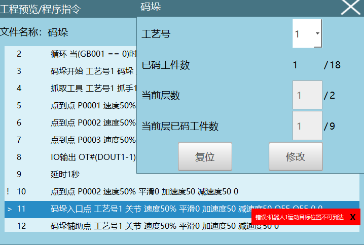
At this time, when palletizing the second workpiece, entry point position shows unreachable. Can modify workpiece 2's entry point configuration value to 4 in position debugging.
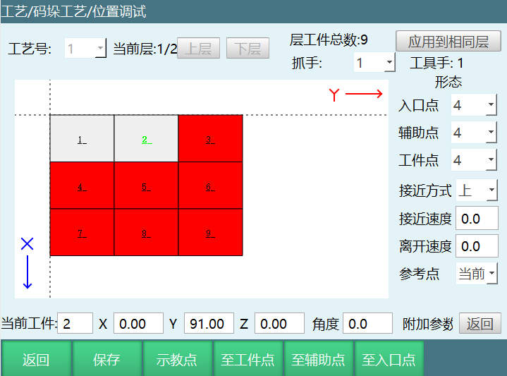
When running job file, after modifying workpiece point configuration value, position unreachable issue may appear when returning to pickup point.
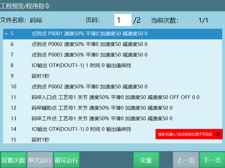
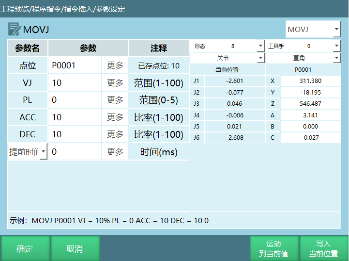
Can manually modify pickup safety point (P0001) configuration value to 8 for normal operation.
Simple Palletizing / Complete Palletizing / Mark Point Palletizing
Enter Craft/Palletizing Process/Palletizing Parameters. Supports 999999 craft number parameters. Can select simple palletizing and complete palletizing, as shown below.
View: Can view all craft number palletizing types set.
Clear Parameters: Clears the currently selected craft number's complete palletizing/simple palletizing parameters.
Copy Parameters: The currently selected craft number's complete palletizing/simple palletizing parameters can be copied to the desired craft number.
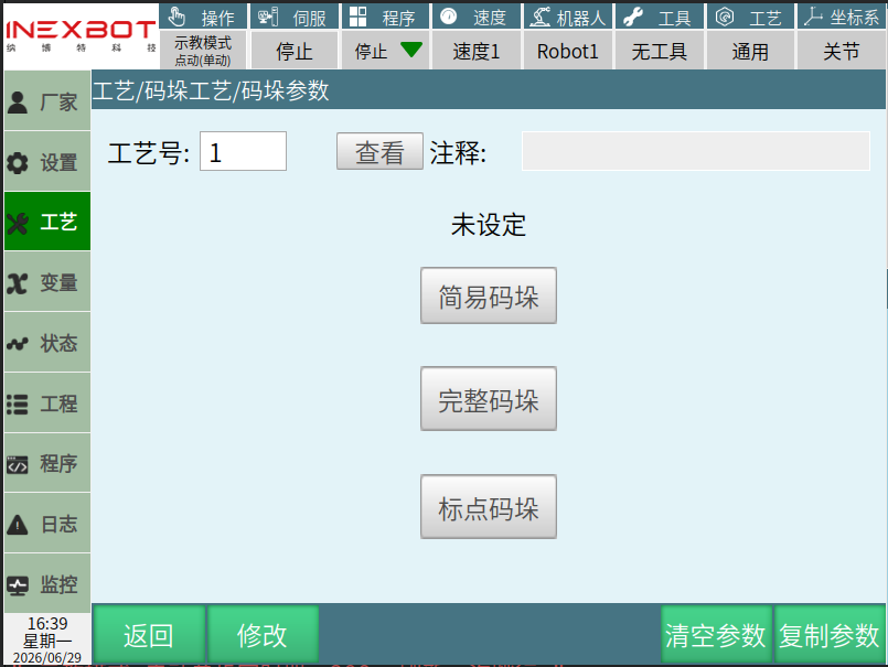
Note: Simple palletizing craft number should not use the same craft number as complete palletizing. If simple palletizing craft number is 1 and parameters are set, then changing craft number 1 to complete palletizing requires re-setting complete palletizing parameters. Using different craft numbers saves time and avoids program runtime errors.
Complete Palletizing
Parameter Setting
Complete palletizing can proceed with gripper settings, pallet settings, workpiece parameters, approach parameters, overlap mode, position settings, and plane mode, as shown below:
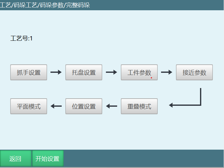
Gripper Settings
Gripper settings configure the tool hands used in the palletizing process.
If two suction cups pick materials separately (one suctions first then switches to the other), set as two grippers;
If two suction cups pick materials simultaneously, set as one gripper;
If two suction cups place materials separately (one places first then switches to the other), set as two grippers;
If two suction cups place materials simultaneously, set as one gripper.
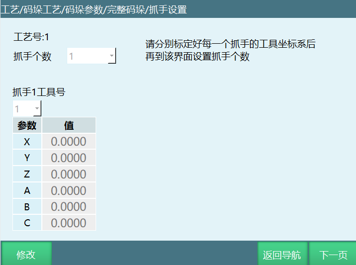
Note: Please calibrate the gripper (tool hand) in [Settings - Robot Parameters - Tool Hand Calibration] interface first, then set the gripper in this interface.
Gripper count: Number of grippers. Set based on actual situation. Maximum 4 grippers.
Gripper X Tool Number: Set the tool hand number corresponding to the gripper (X is 1 in the figure). Tool hand parameters need to be calibrated in advance.
Parameter Values: After completing tool coordinate calibration in tool hand calibration interface, each axis's parameter values after selecting the calibrated tool hand number in this interface.
Pallet Settings
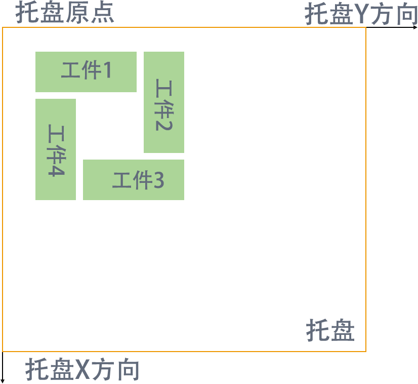
Pallet settings configure the pallet user coordinate engineering. In this interface, calibrate the pallet origin, pallet Y direction, and pallet X direction.
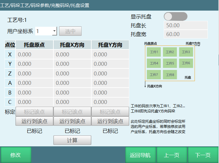
User Coordinate System: Pallet coordinates. Select the user coordinate to calibrate based on need. Calibrate pallet coordinate (user coordinate). If coordinate system position is changed later in user coordinate calibration, the coordinate system here will also change.
Show Pallet: Switch controls whether to show pallet preview in plane mode.
Pallet Length: Set pallet size.
Pallet Width: Set pallet size.
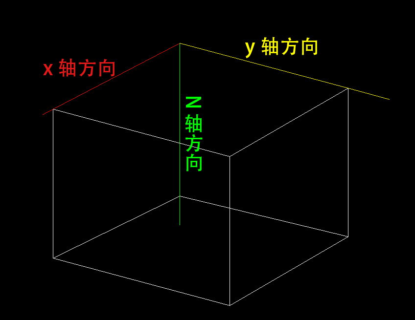
Note: Please use the tool hand selected for gripper 1 to calibrate. When not calibrating user coordinate (pallet coordinate), when user coordinate parameter value is 0, it is the same as Cartesian coordinate system.
When marking X and Y directions, must be based on robot's original X, Y directions. Otherwise marked pallet Z direction will be downward, and second layer will be stacked downward!
Workpiece Parameters
Workpiece parameters can set the length, width, height and gap of the workpiece to be palletized in user coordinates;
Length, width, and height are the lengths in YXZ directions in pallet coordinate system (user coordinate system), as shown below:
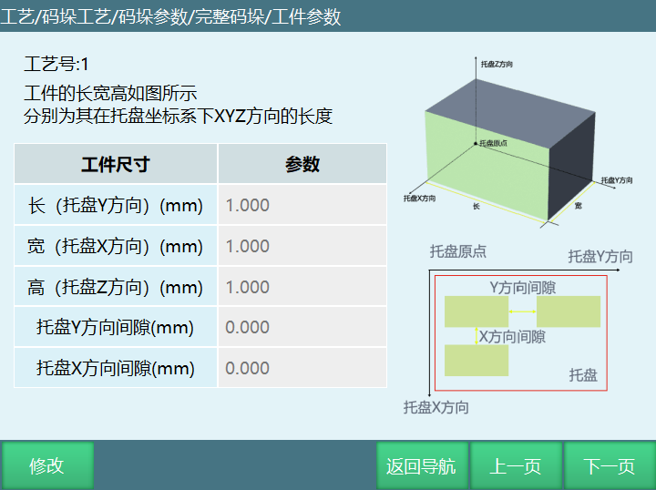
Workpiece size parameter description:
Length: Workpiece length in Y direction in pallet coordinate system.
Width: Workpiece length in X direction in pallet coordinate system.
Height: Workpiece length in Z direction in pallet coordinate system.
Pallet Y direction gap: Gap distance between two workpieces in Y axis direction in pallet coordinate system.
Pallet X direction gap: Gap distance between two workpieces in X axis direction in pallet coordinate system.
Approach Parameters
Approach parameters can set approach method as descending approach or approach descending, and XYZ direction offset distances.
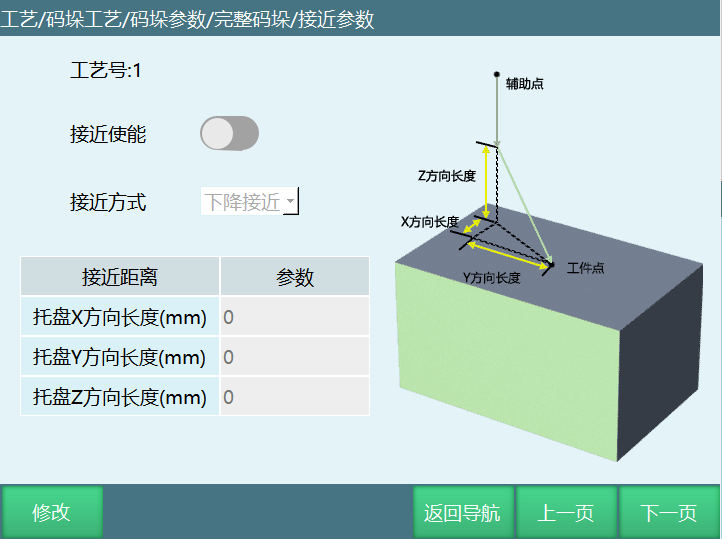
Approach Enable
Need to turn on to use palletizing approach function. If enable button is turned on but approach distance is not set, approach enable will not take effect.
Approach Method
Descending Approach: Robot goes to auxiliary point first, then moves to approach point based on offset distance, then moves to workpiece point.
Approach Descending: Robot goes to auxiliary point first, then moves to approach point based on offset distance, moves from approach point to above workpiece point, then moves to workpiece point.
Plane Mode
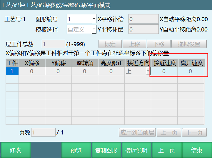
In palletizing plane mode, custom stack pattern adds the ability to set individual workpiece's entry/exit speed. If not filled, defaults to approach point instruction speed. Speed differs based on interpolation method. If interpolation is joint, speed less than 100 is the corresponding value, greater than 100 is 100. Acceleration/deceleration defaults to equal speed; if linear, the filled value is used (except negative values) and cannot exceed Cartesian parameters. Acceleration/deceleration defaults to 10% of speed.
Can also set individual or overall approach direction.
Apply to Current Layer: Set the selected workpiece's approach direction and entry/exit speed as all workpieces' parameters for the entire layer.
Position Debugging
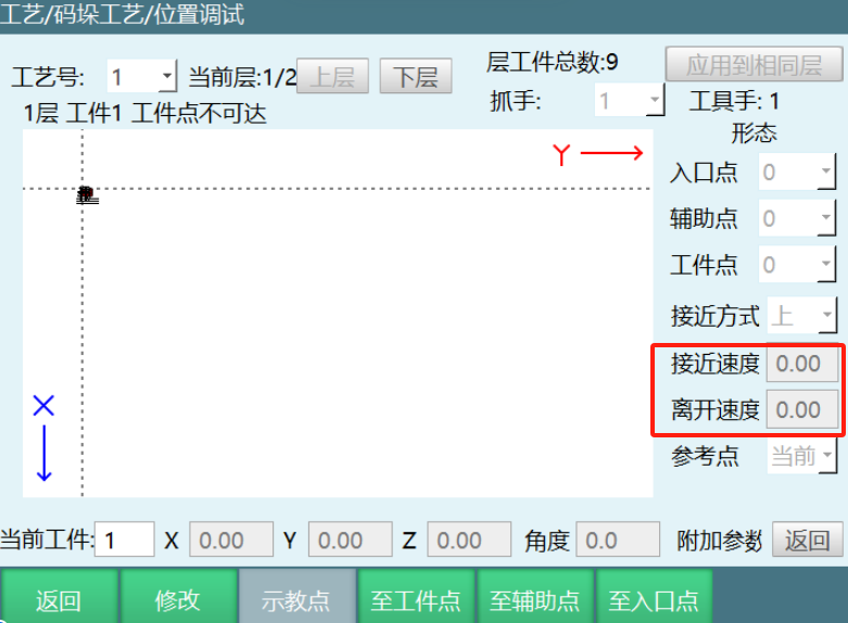
In position debugging, can also set individual workpiece's exit/entry speed and approach direction.
Gripper: Position debugging interface adds gripper selection item, as shown. Operation steps: Craft -> Palletizing Process -> Position Debugging. Can modify different grippers to adapt to different palletizing positions.
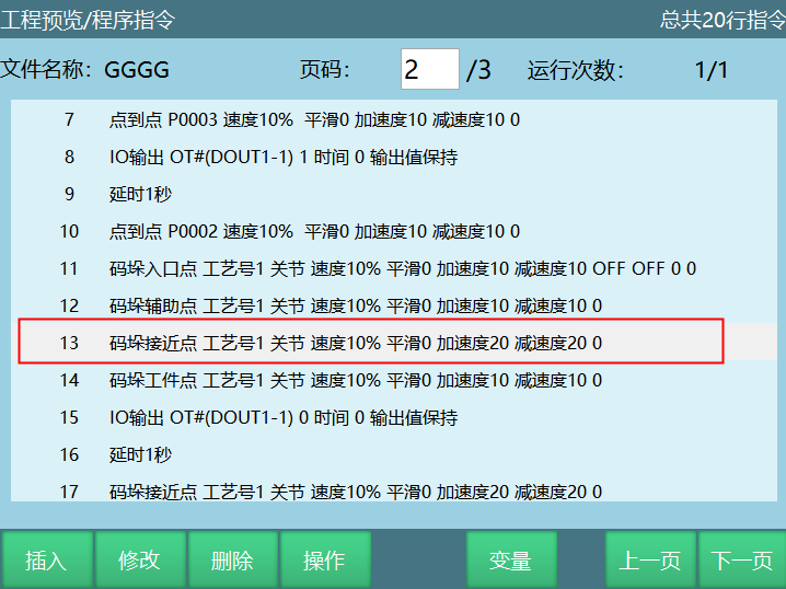
Palletizing Approach Point
New instruction palletizing approach point is the transition point between auxiliary point and workpiece point, which is the point to reach according to the approach method.
Overlap Mode
Overlap mode can set palletizing layer count and pattern template selection and other related parameters, as shown below:
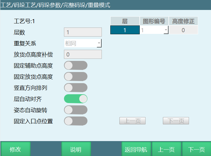
Layer Count: Total palletizing layers. Fill based on actual need.
Repeat Relationship: Repeat relationship between each layer.
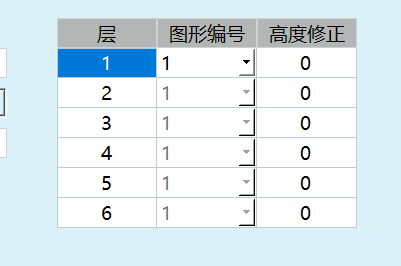
Select Same: Each layer uses the same pattern template.
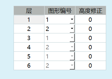
Select Alternate: Pattern templates alternate every two layers.
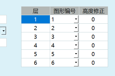
Select Custom: Users select each layer's pattern template individually.
Same: Every layer's pattern template is the same. Palletizing uses the same pattern template. When selecting this option, only the first layer in the right list is modifiable. After modification, all layers below change accordingly. Below shows layer count selected as 6, repeat relationship selected as Same.
Alternate: Two pattern templates alternate. After selecting this option, only the first two layers in the right list are modifiable. After modification, all layers below repeat the two layers' pattern numbers. Below shows layer count selected as 6, repeat relationship selected as Alternate.
Custom: Each layer's pattern template can be set individually. Below shows layer count selected as 6, repeat relationship selected as Custom.
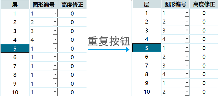
Repeat: When repeat relationship uses Custom and layer count is large, if all layers repeat the first N layers' pattern templates, after filling the first N layers' pattern templates, select the N+1th layer, click this button, layers below automatically repeat (can only use this function on the first page).
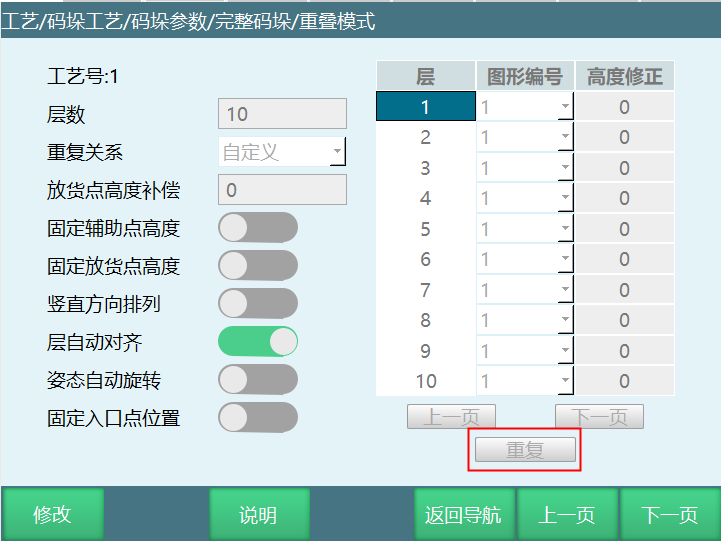
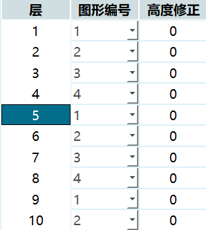
Fixed Auxiliary Point Height: If palletizing layer count is two, turning on this button makes the first layer workpiece and second layer workpiece share the same auxiliary point position. Auxiliary point will not shift in Z+ direction when running the second layer workpiece.
For example: In a box enclosed on all sides, if there are many workpieces to palletize, the set workpiece auxiliary point will get higher as palletizing count increases, possibly exceeding robot joint parameter limits. To prevent this error, turn on fixed auxiliary point height button, set the fixed auxiliary point height position. This way, as palletizing count increases, auxiliary point height remains the same, avoiding joint parameter limit exceedance and ensuring operator safety.
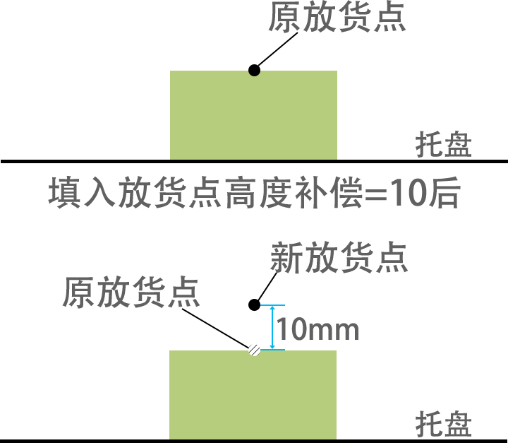
Placement Point Height Compensation: After filling, all workpieces' placement point height will shift. Shift height can be filled based on actual need. Positive value shifts in Z+ direction, negative value shifts in Z- direction (this parameter is invalid during depalletizing, only visible when program runs).
Fixed Placement Point Height: After selecting, placement point height is the same for every layer during palletizing. Height is the marked workpiece point height (only effective during palletizing). If palletizing layers are more than one (two layers as example), turning on this button makes every layer's every workpiece point at the same height, not shifting in Z+ direction during second layer palletizing.
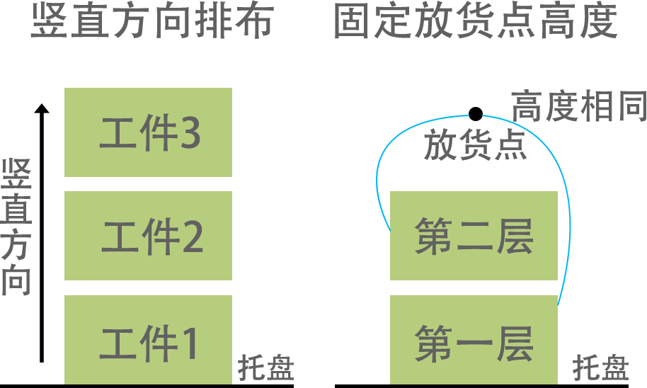
Vertical Direction Arrangement: After selecting vertical direction arrangement, will complete one vertical column first before palletizing the next vertical column.
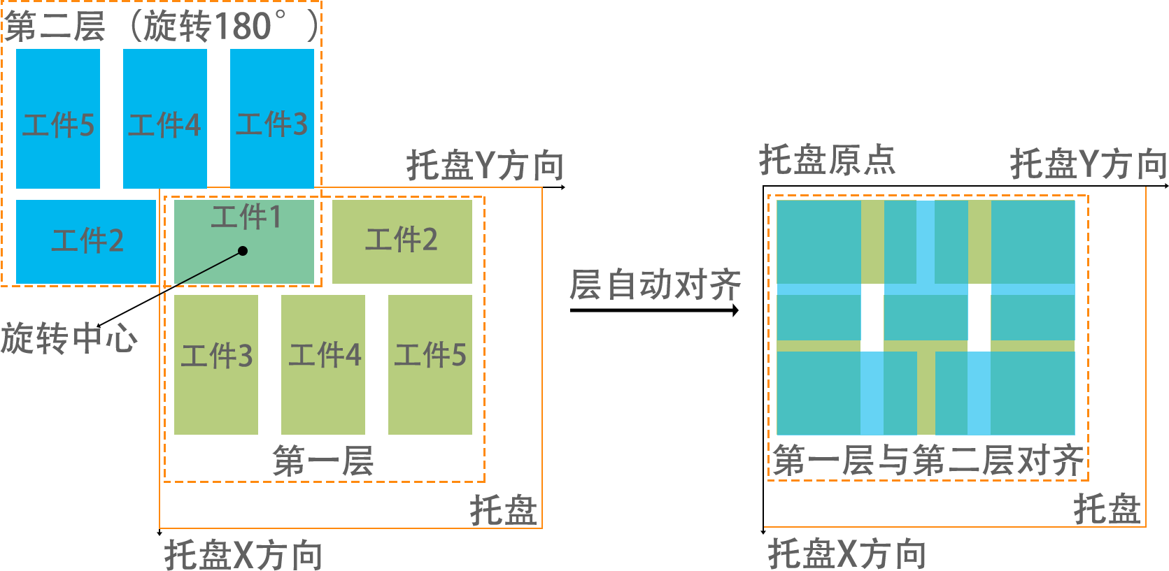
Layer Auto-Align: After selecting layer auto-align, each layer template is automatically aligned. X axis and Y axis offsets are automatically calculated.
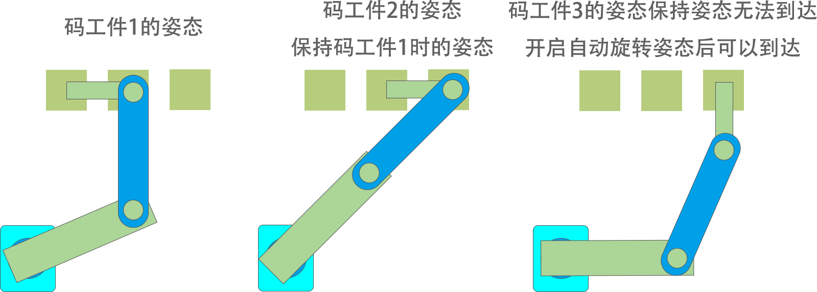
Attitude Auto-Rotate: After selecting, when palletizing and tool hand cannot reach auxiliary point and placement point with a fixed attitude but can reach after rotating the tool hand attitude, it will auto-rotate. This function only works when both auxiliary point and workpiece point use joint interpolation.
Fixed Entry Point Position: After picking, every workpiece will be at the same entry point. Z axis is optimized during entry point process.
Position Setting: Can set palletizing workpiece point, auxiliary point, entry point. Please perform position marking with the tool hand selected in gripper settings.
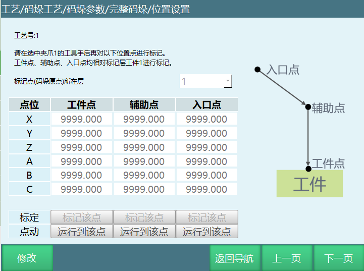
Mark Point (Palletizing Origin) Layer: The layer where current calibration workpiece point is located. Saves the process of clearing the stack. Can directly select mark current layer.
Workpiece Point: The first pickup point or last placement point of the marked layer (Note: Workpiece order in palletizing parameter setting interface follows palletizing order, depalletizing order is reversed).
Auxiliary Point: Used with workpiece point to make workpiece placement safer. Generally set above the workpiece point. If workpiece needs rotation angle, it will rotate before reaching auxiliary point. This point automatically shifts with workpiece placement position.
Entry Point: Pallet entry point. To prevent robot collision with other objects, set robot's safe position as entry point. This point automatically shifts in Z axis direction with workpiece placement position. Palletizing entry point instruction turns on XYZ optimization. ABC axis coordinates change when running to entry point.
Mark This Point: Robot moves to position first, then click mark this point.
Run to This Point: Marked value can be moved to after clicking save. Without save, moves to previously marked point. To move to this point, press DEADMAN button then click this button (Note: Please perform position marking with the tool hand selected in gripper settings).
Plane Mode
This mode sets palletizing pattern template:
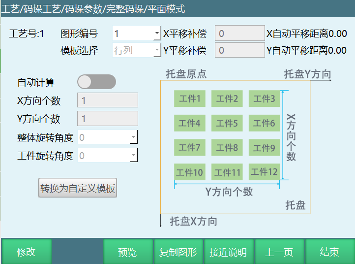
Pattern Number: Pattern template number.
Template Selection: 4 fixed pattern templates and custom pattern templates: Row-Column, Cross-Stack, Spiral, Pinwheel, Custom.
X Translation Compensation: Overall pattern template offset relative to original palletizing position in pallet coordinate system X axis.
Y Translation Compensation: Overall pattern template offset relative to original palletizing position in pallet coordinate system Y axis.
Auto Calculate: Based on pallet setting interface calibrated user coordinate system, generates a rectangular pallet. Automatically calculates how many workpieces can be placed in X and Y directions based on workpiece size.
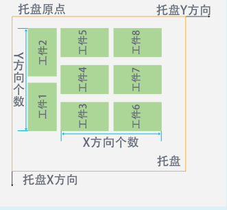
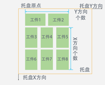
X Direction Count (Row-Column template, Cross-Stack template): Number of workpieces in X direction (Cross-Stack X direction count is the number of workpiece long side on X axis).
Y Direction Count (Row-Column template, Cross-Stack template): Number of workpieces in Y direction (Cross-Stack Y direction count is the number of workpiece long side on Y axis).
Overall Rotation Angle (Row-Column template, Cross-Stack template, Spiral template): Angle of overall clockwise rotation around the first workpiece point. Can rotate 0°, 90°, 180°, -90°.
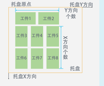
(Overall rotation angle 0 degrees)
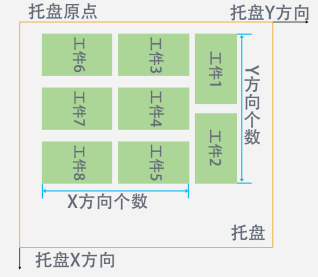
(Overall rotation angle 90 degrees)
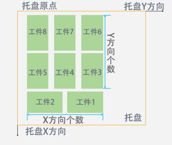
(Overall rotation angle 180 degrees)
(Overall rotation angle -90 degrees)
Workpiece Rotation Angle (Row-Column template, Cross-Stack template, Spiral template, Pinwheel template): All workpieces in pattern template rotate clockwise by this angle. Can rotate 0°, 90°, 180°, -90°.
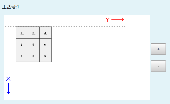
Preview: Preview the set pattern template. Can be used to check if pattern template is set correctly. Template selection is Cross-Stack template here. X direction workpiece count is 3, Y direction count is 3.
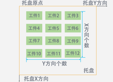
Row-Column: All workpieces in the layer have the same direction, stacked sequentially. Below shows X direction workpiece count 4, Y direction count 3.
Cross-Stack: Workpiece directions include horizontal and vertical, arranged alternately (this template's X direction count is workpiece long side count on X axis, Y direction count is workpiece long side count on Y axis).
Spiral: 4 workpieces per layer, arranged in spiral pattern (second workpiece rotates 90° clockwise from first, third rotates 180° clockwise from first, fourth rotates 90° counterclockwise from first).
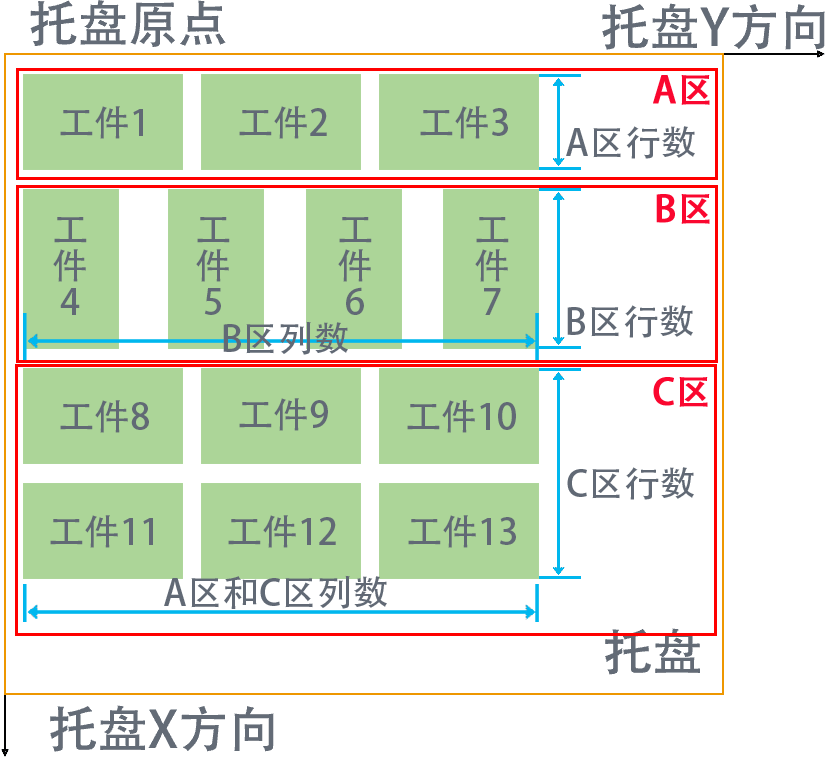
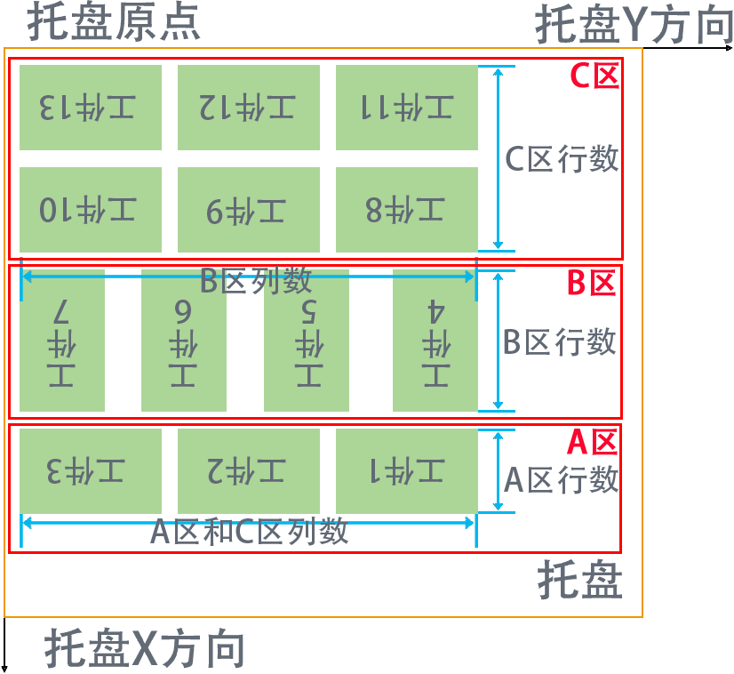
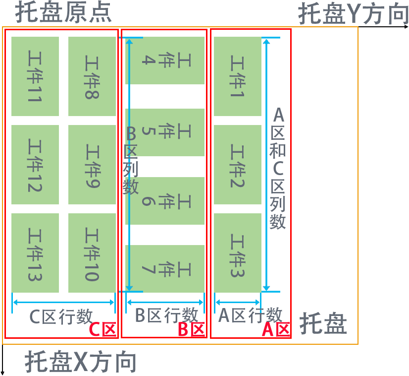
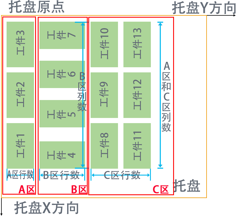
Pinwheel: Workpieces divided into three areas: A, B, C; Area A and C column counts can be set together, Area B column count set separately (as shown, Area B workpieces 4-7 rotate 90° clockwise from Area A workpieces 1-3 and Area C workpieces 8-13). As shown in Figure 1, Area A and C workpieces maintain left-right alignment based on Area B with the most columns.
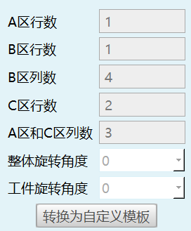
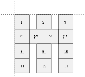
Figure 1
Overall rotation angle 0°
Overall rotation angle 180°
Overall rotation 90°
Overall rotation -90°
Custom: Custom pattern template.
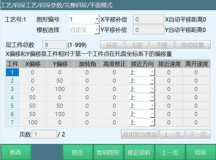
Layer Workpiece Total: Palletizing workpiece total. Set based on actual need. Note: Modifying workpiece total will clear all workpiece parameters.
Calibrate: Can set palletizing point positions yourself. After determining positions, click calibrate button. If you want to modify the first set palletizing workpiece positions, click the workpiece number, move robot to desired position, then click calibrate.
Move Up: After workpiece point calibration, to set palletizing workpiece 2's position as workpiece 1's position, click move up button. Workpiece 1's position changes.
After workpiece 2 moved up:


Move Down: After workpiece point calibration, to set palletizing workpiece 1's position as workpiece 3's position, click move down button. Workpiece 3's position changes.
After workpiece 1 moved down:

X Offset: Workpiece point offset on X axis.
Y Offset: Workpiece point offset on Y axis.
Rotation Angle: Workpiece rotation angle relative to previous workpiece point angle.
Height Correction: After filling, workpiece point, auxiliary point, entry point height will shift during this workpiece palletizing. Positive value shifts in Z+ direction, negative value shifts in Z- direction. Can correct workpiece point, auxiliary point, entry point heights.
Drag Setting: After palletizing workpiece count is set, click drag setting button. As shown, can drag workpiece point to any desired position. In custom mode, besides filling XY offset, can also directly drag workpieces.
Note: Before entering drag setting, first set layer workpiece total in custom mode, click save, then click Modify - Drag Setting. After drag setting completes, first click save button in drag setting, return to custom interface, click save again.
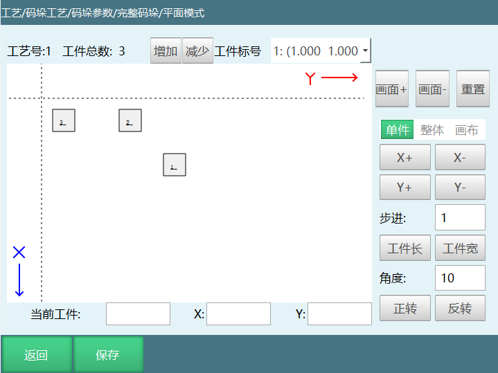
Increase: Increase workpiece count. Increase based on need.
Decrease: Decrease workpiece count.
Reset: Restore canvas to initial state.
Zoom In: Zoom in.
Zoom Out: Zoom out.
Canvas: Can drag canvas.
Single/Overall: Single/Overall workpiece offset in X or Y direction. Turn on single/overall button to offset all workpieces in X or Y direction. Turn off to offset currently selected workpiece in X or Y direction.
X+/X-: Overall offset in X positive or negative direction by step value.
Y+/Y-: Overall offset in Y positive or negative direction by step value.
Step: Workpiece offset amount in X or Y direction.
Workpiece Length/Width: Click button to show workpiece length/width values in step parameter box.
Angle: Set rotation angle each time. Turn on single/overall button, all workpieces rotate. Turn off, currently selected workpiece rotates.
Clockwise/Counterclockwise: Workpiece rotates by set angle value.
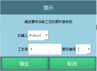
Copy Pattern: Can copy current craft number's stack pattern across robots.
Simple Palletizing
Parameter Setting
Simple palletizing parameter setting proceeds with gripper settings and position settings.
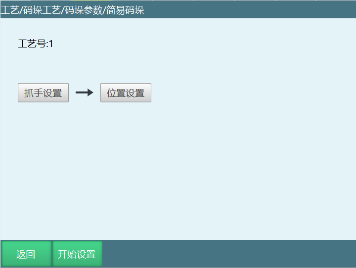
Current Usage Type: When simple palletizing and complete palletizing share palletizing number, need to set correct type before use.
Gripper Settings
Gripper settings can select palletizing gripper (tool hand). Please calibrate the gripper (tool hand) in [Settings - Tool Hand Calibration] interface first, then set gripper in this interface, as shown:
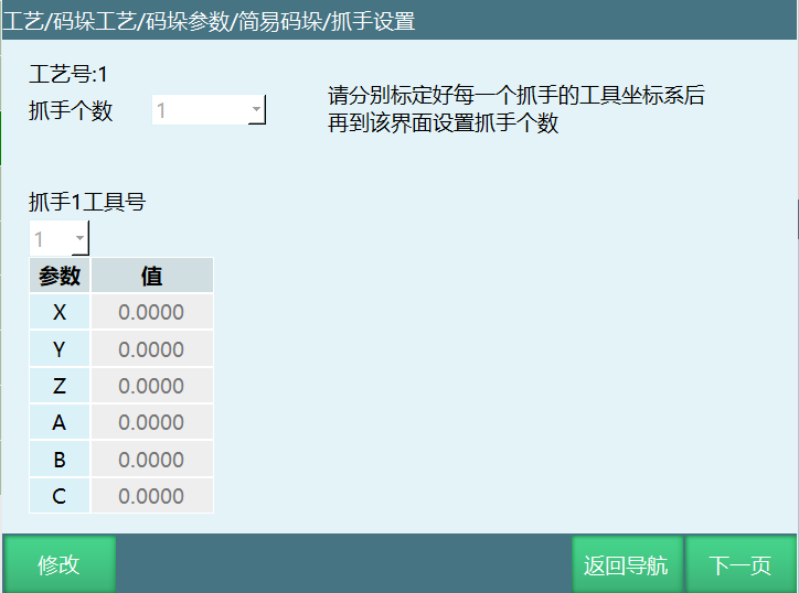
Gripper Count: Number of grippers. Set based on actual situation.
Gripper X Tool Number: Set the tool hand number corresponding to the gripper. Tool hand parameters need to be calibrated in advance.
Parameter Values: Parameter values are tool hand end offsets. Can only select here, cannot calibrate.
Position Settings
Simple palletizing only provides row-column mode stack pattern. All palletizing directions and position points are marked. Even if marked pattern is not rectangular, it will palletize according to marked direction.
Simple palletizing only needs to set palletizing gripper and mark 6 position points. Gripper settings are the same as complete palletizing. If palletizing has multiple grippers for separate picking and palletizing, use the first gripper to mark position points. Other grippers' actions are automatically calculated.
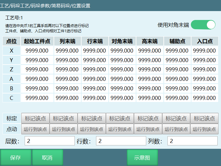
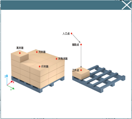
Start Workpiece Point: First workpiece position during palletizing.
Column End: Last workpiece position in column (user coordinate X axis) direction during palletizing. (When column count is 1, column end is not shown in table)
Row End: Last workpiece position in row (user coordinate Y axis) direction during palletizing. (When row count is 1, row end is not shown in table)
Height End: First workpiece position of the last layer during palletizing. (When layer count is 1, height end is not shown in table)
Diagonal End: Intersection of row end diagonal end line and column end diagonal end line. Used to calibrate position offset when there are many palletizing points. (When switch is not turned on, diagonal end is not shown in table)
Auxiliary Point: Palletizing auxiliary point. Recommended to set above start workpiece point.
Entry Point: Palletizing entry point. Recommended to set as a safety point outside the pallet.
Layer Count: Total palletizing layers.
Row Count: Total palletizing rows.
Column Count: Total palletizing columns.
Diagram:
Generate File
Using generate file can generate standard palletizing/depalletizing programs. Need to set parameters in craft number in advance.
Simple palletizing generate file function cannot be used without IO. As shown:
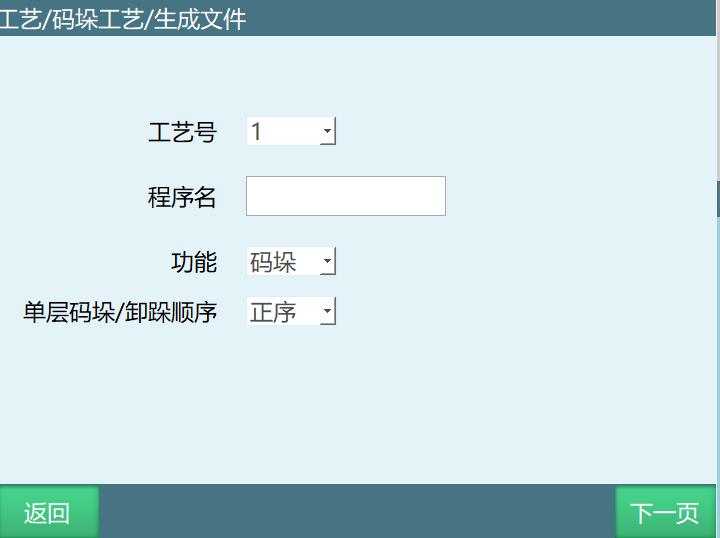
Current Usage Type: When simple palletizing and complete palletizing share palletizing number, need to set correct type before use.
Parameter Introduction:
Craft Number: After selecting craft number, confirm if palletizing current usage type is set.
Program Name: Must start with English letters (pure Chinese also works).
Function: Palletizing, Depalletizing.
Single Layer Palletizing/Depalletizing: Forward, Reverse.
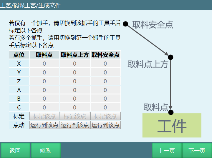
Mark This Point: Teach to corresponding point and click mark.
Run to This Point: Click to verify if point teaching is correct.
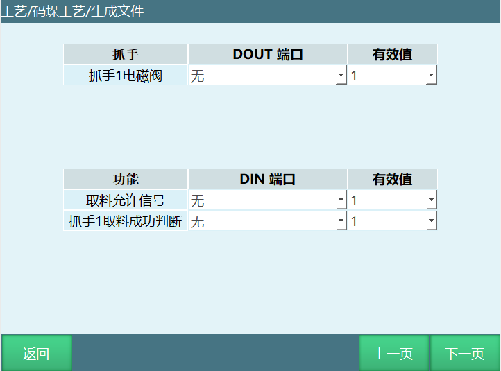
Gripper Solenoid Valve: Gripper IO output signal. Gripper solenoid valve DOUT port must be set. Generate file function only supports 1 output. For multiple outputs, can return to project to modify output signal instruction after job file is generated.
Pick Permission Signal: Wait for pick permission signal before palletizing picking. Select based on own situation.
Gripper Pick Success Signal: Judge gripper pick success signal.
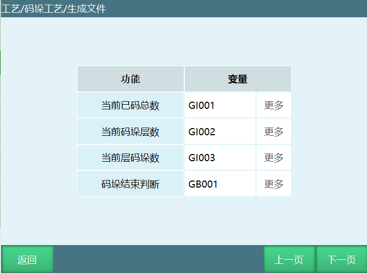
Note: Current total palletized, current palletizing layer, current layer palletized count can be viewed in Craft Bar - Palletizing Process interface if not selecting variable type when generating job.
Current Total Palletized: Cache current total palletized variable value to set variable.
Current Palletizing Layer: Cache current palletizing layer variable value to set variable.
Current Layer Palletized Count: Cache current layer palletized count variable value to set variable.
Palletizing End Judgment: After palletizing completes, change variable value to exit while loop.
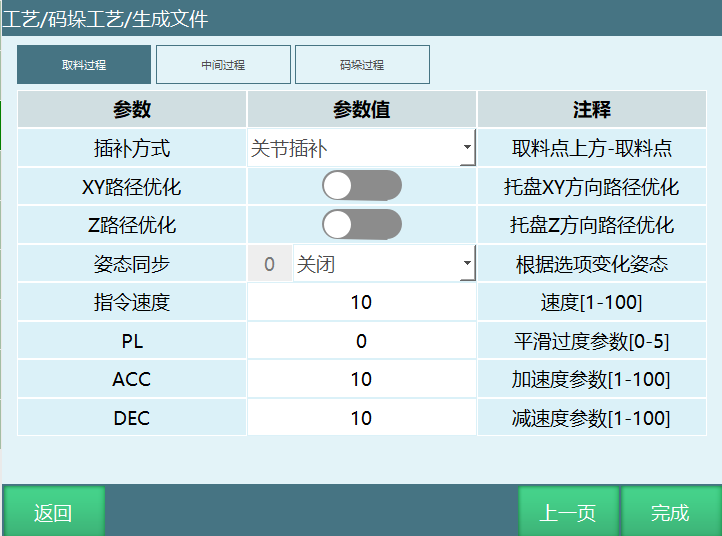
Pick Process: Above pick point, pick point. Can change to joint interpolation or linear interpolation.
Middle Process: Pick safety point, palletizing entry point. Can change to joint interpolation or linear interpolation.
Palletizing Process: Palletizing auxiliary point, workpiece point. Can change to joint interpolation or linear interpolation.
XY Path Optimization: Click to turn on. Can optimize pallet XY direction path.
Z Path Optimization: Click to turn on. Can optimize pallet Z direction path.
Attitude Synchronization:
Off: Attitude follows set point execution.
Manual Input: Move to entry according to manually filled attitude.
Auto Calculate Attitude: Based on the distance ratio from entry point to auxiliary point and auxiliary point to workpiece point, automatically calculates the trajectory attitude between entry point and auxiliary point/workpiece point. During motion, the C attitude continuously rotates. For example, if the distance ratio from entry point to auxiliary point to auxiliary point to workpiece point is 2:8, and C attitude rotates 100° total from entry point to workpiece point, then 20° rotates from workpiece point to auxiliary point, and the remaining 80° rotates from auxiliary point to workpiece point.
Position Debugging
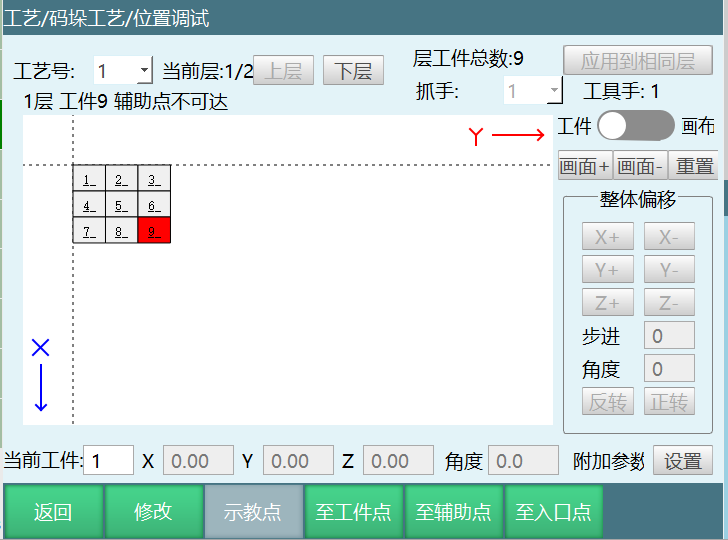
Parameter Introduction:
Craft Number: Current parameter's craft number.
Layer Workpiece Total: Total workpieces in this layer.
Upper Layer: Switch to upper layer.
Lower Layer: Switch to lower layer.
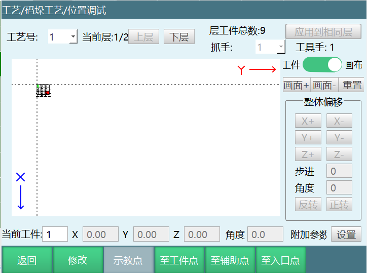
Workpiece/Canvas: Button off can drag workpiece, button on can drag canvas.
Reset: Restore canvas to initial state.
Zoom In: Zoom in.
Zoom Out: Zoom out.
Overall Offset: Offset all workpieces.
X+: Overall offset in X positive direction by step value.
X-: Overall offset in X negative direction by step value.
Y+: Overall offset in Y positive direction by step value.
Y-: Overall offset in Y negative direction by step value.
Z+: Overall offset in Z positive direction by step value.
Z-: Overall offset in Z negative direction by step value.
Step: Set offset step value each time.
Angle: Set rotation angle each time.
Clockwise: All workpieces rotate clockwise by angle value.
Counterclockwise: All workpieces rotate counterclockwise by angle value.
Apply to Same Layer: Apply current layer's set parameters to layers with the same pattern number.
Note:
- Set point offset through current workpiece row fill values. After save, current layer's current workpiece offset takes effect. To apply to layers with the same number, operation steps: click Modify --> Modify current workpiece row's offset value --> Click apply to same layer button --> Click save (apply to same layer only applies x offset, y offset and angle offset, z offset is not applied to same layer).
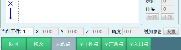
Current Workpiece: 1 indicates workpiece number;
X: Current workpiece offset in X axis positive or negative;
Y: Current workpiece offset in Y axis positive or negative;
Z: Current workpiece offset in Z axis positive or negative;
Angle: Current workpiece rotation degrees.
Workpiece/Canvas Function Demo
Button on drags entire canvas, but doesn't affect workpiece coordinates.
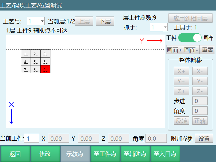
Reset Function Demo
After clicking reset button, canvas returns to initial position, but canvas size is not reset.
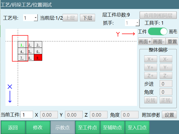
Zoom In, Zoom Out Function Demo
Click zoom in, canvas enlarges.
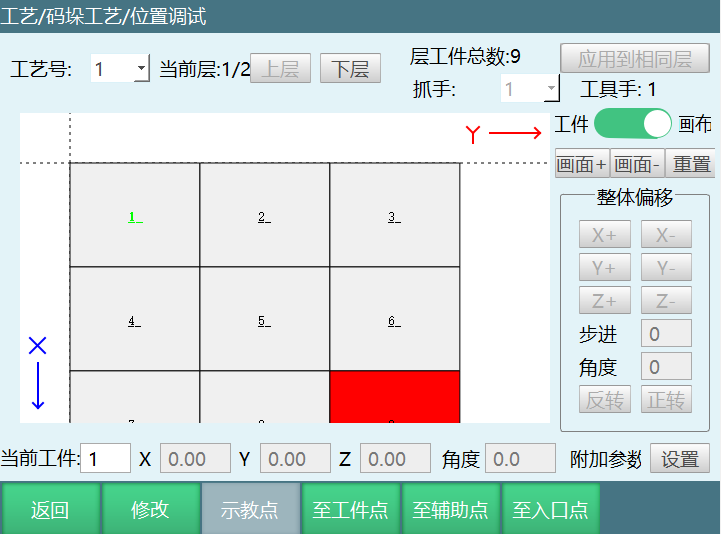
Click zoom out, canvas shrinks.
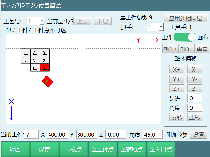
Single/Overall Offset Function Demo
Fill coordinate values. Also offset X, Y, Z, angle values (since it's a plane, Z axis effect is not visible). For example, fill X:400, Y:300, Z:0, angle 45.
Palletizing Status
Palletizing status can be used to view current palletizing status. If palletizing needs to start from the middle, can set the layer count and count needed.
Palletizing count resets after controller restart. Re-running does not reset.
Palletizing status can be viewed in [Status Bar - Craft - Palletizing]. There are two methods; can set in operation parameters, craft selection bar selects palletizing craft (selecting palletizing in operation parameters will always default to palletizing craft); can also directly select palletizing in teach pendant top navigation bar craft, as shown:
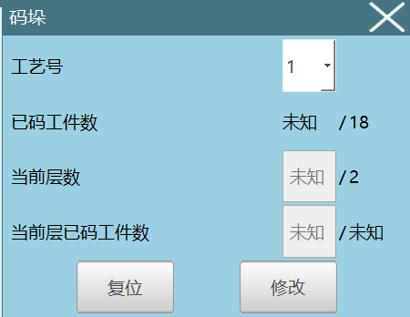
Craft Number: Palletizing craft number.
Palletized Count: Palletized count / Total count.
Current Layer: Current palletizing layer / Total layers (if palletizing needs to start from middle, set the layer needed). Taking two layers as example, when robot is palletizing the first layer workpiece, can set current layer to 2, then robot will palletize the second layer workpiece. The palletized count display will also change.
Current Layer Palletized Count: Current layer palletized count / Current layer total count (if palletizing needs to start from middle, set the count needed). For example, if currently palletizing the 3rd workpiece and want to start from the 7th workpiece, modify current layer palletized count to start palletizing from the desired count.
Reset: Clear recorded palletizing data.
Modify: During palletizing process, click modify to modify current layer and current layer palletized count.
Mark Point Palletizing
Parameter Setting:
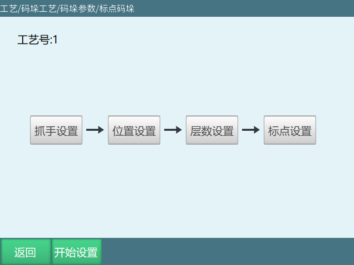
Mark point palletizing proceeds with gripper settings, position settings, layer settings, mark settings, as shown:
Gripper Settings
Gripper settings configure the tool hands used in the palletizing process.
If two suction cups pick materials separately (one suctions first then switches to the other), set as two grippers;
If two suction cups pick materials simultaneously, set as one gripper;
If two suction cups place materials separately (one places first then switches to the other), set as two grippers;
If two suction cups place materials simultaneously, set as one gripper.
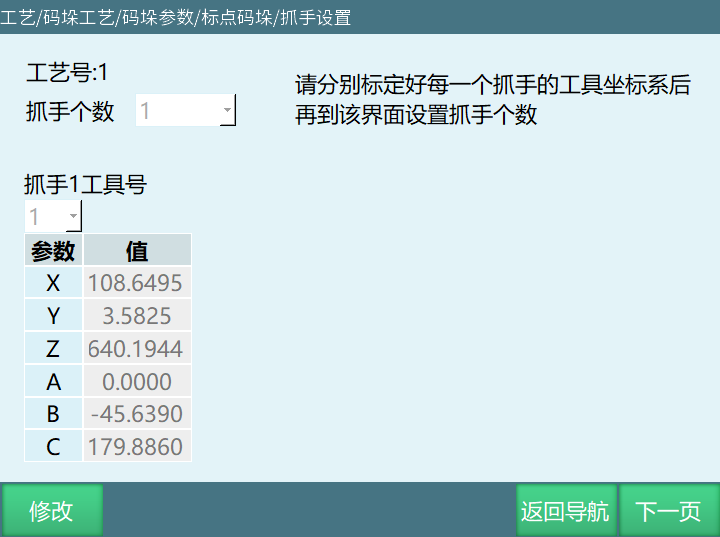
Note: Please calibrate the gripper (tool hand) in [Settings - Tool Hand Calibration] interface first, then set the gripper in this interface.
Terminology:
Gripper Count: Number of grippers. Set based on actual situation. Maximum 4 grippers.
Gripper X Tool Number: Set the tool hand number corresponding to the gripper (X is 1 in the figure). Tool hand parameters need to be calibrated in advance.
Parameter Values: After completing tool coordinate calibration in tool hand calibration interface, each axis's parameter values after selecting the calibrated tool hand number in this interface.
Position Settings:
Can set palletizing workpiece point, auxiliary point, entry point. Please perform position marking with the tool hand selected in gripper settings.
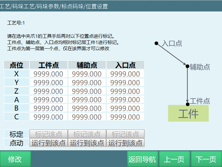
Mark Layer Number: The layer where current calibration workpiece point is located. Saves the process of clearing the stack. Can directly select mark current layer.
Workpiece Point: The first pickup point or last placement point of the marked layer (Note: Workpiece order in palletizing parameter setting interface follows palletizing order, depalletizing order is reversed).
Auxiliary Point: Used with workpiece point to make workpiece placement safer. Generally set above the workpiece point. If workpiece needs rotation angle, it will rotate before reaching auxiliary point. This point automatically shifts with workpiece placement position.
Entry Point: Pallet entry point. To prevent robot collision with other objects, set robot's safe position as entry point. This point automatically shifts in Z axis direction with workpiece placement position. Palletizing entry point instruction turns on XYZ optimization. ABC axis coordinates change when running to entry point.
Mark This Point: Robot moves to position first, then click mark this point.
Run to This Point: Marked value can be moved to after clicking save. Without save, moves to previously marked point. To move to this point, press DEADMAN button then click this button (Note: Please perform position marking with the tool hand selected in gripper settings).
Layer Settings:
Can set palletizing layer count, add, delete or copy layers, reset layer (set based on actual situation).
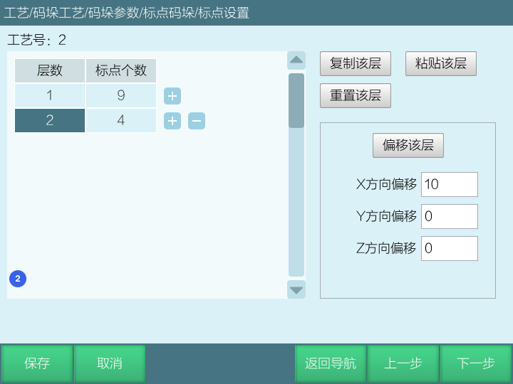
Layer Count: Total layers.
Mark Point Count: Workpiece count for corresponding layer.
Copy Layer: Copy selected layer's data.
Paste Layer: Paste copied layer data to the layer below the selected layer.
Reset Layer: Reset selected layer's data.
Offset Layer: Offset the layer's overall data in XYZ direction.
Mark Settings
Set workpiece position, size, layer workpiece count increase or decrease.
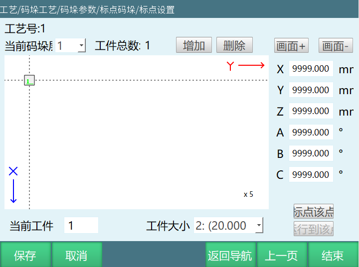
Current Palletizing Layer: Currently set layer.
Workpiece Total: Current layer's workpiece total.
Increase: Increase current layer workpiece count.
Delete: Delete current layer's selected workpiece.
Zoom In: Zoom in.
Zoom Out: Zoom out.
X: Workpiece's X coordinate.
Y: Workpiece's Y coordinate.
Z: Workpiece's Z coordinate.
A: Workpiece's A coordinate.
B: Workpiece's B coordinate.
C: Workpiece's C coordinate.
Current Workpiece: Selected current layer workpiece.
Workpiece Size: Workpiece length and width.
Mark This Point: Mark current workpiece position.
Run to This Point: Run to mark position.
Palletizing Instructions
PALON (Start Palletizing)
Function: Palletizing start judgment.
Craft Number: Select craft number with palletizing type set.
Type: Palletizing, Depalletizing.
Single Layer Palletizing/Depalletizing: Forward, Reverse.
Current Total Palletized Variable: Cache current total palletized variable value to set variable.
Note: Can control which layer and which workpiece to palletize by reading variable.
Current Palletizing Layer Variable: Cache current palletizing layer variable value to set variable.
Note: Can control which layer and which workpiece to palletize by reading variable.
Current Layer Palletized Variable: Cache current layer palletized variable value to set variable.
Note: Can control which layer and which workpiece to palletize by reading variable.
Example: PALON ID=1 SORT=0 TYPE=0 [variable name][variable name][variable name].
Note: Palletizing start PALON instruction's 3 count variables are directly written to config, no need to use FORCESET write to file instruction.
PALGRIPPER (Switch Gripper)
Function: Select gripper.
Craft Number: Select craft number with palletizing type set.
Gripper: Gripper 1, Gripper 2, Gripper 3, Gripper 4.
Example: PALGRIPPER ID=1 GRIPPERS=1.
PALENTER (Palletizing Entry Point)
Function: Palletizing entry point.
Craft Number: Select craft number with palletizing type set.
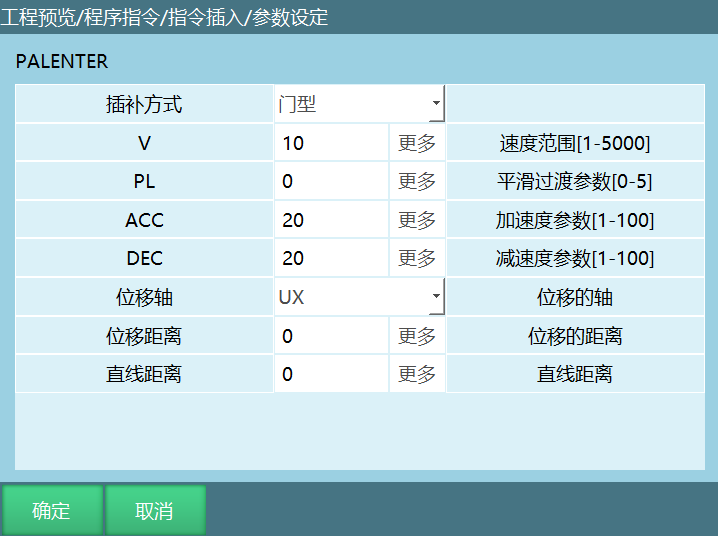
Interpolation Method: Joint interpolation, Linear interpolation, Circular arc interpolation, Arch interpolation.
Joint Interpolation: Robot moves to this point via joint interpolation.
Linear Interpolation: Robot moves to this point via linear interpolation.
Circular Arc Interpolation: Robot forms circular arc trajectory with two other points (previous point MOVJ/MOVL, next point MOVC).
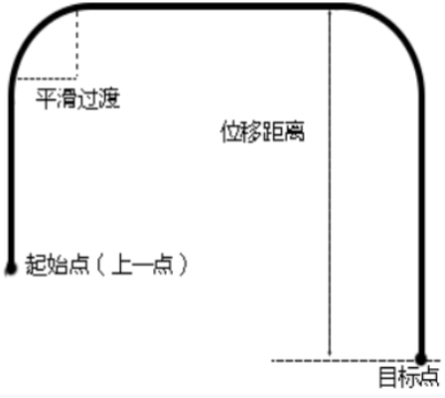
Arch Interpolation: Arch trajectory motion is widely used in material handling and 3C industries. Robot arm moves to target point through arch trajectory (rise -> translate -> descend) to avoid material friction.
VJ: Speed range 1-100.
PL: Smoothing range 0-5.
ACC: Acceleration range 1-100.
DEC: Deceleration range 1-100.
XY Optimization: Optimize XY axis motion path.
Z Optimization: Optimize Z axis motion path. Need to insert a fixed point before palletizing.
When entry point height is lower than fixed point, entry point height is on the same level as fixed point and auxiliary point (same line in side view, not same line in top view, XY axes unchanged).
When entry point height is between fixed point and auxiliary point, entry point height is unchanged.
When entry point height is above fixed point and auxiliary point, entry point height is optimized to the same level as fixed point.
When entry point and auxiliary point heights are both higher than fixed point, entry point height is optimized to the same level as auxiliary point.
Attitude: Off: Attitude follows set point execution.
Manual Input: Move to entry according to manually filled attitude.
Auto Calculate Attitude: There is an attitude before and after entry point. Entry point attitude is calculated between these two attitudes.
Early Time: Range non-negative integer, unit ms. Execute next instruction early.
Example: PALENTER ID=1 MOVJ VJ=10% PL=0 ACC=20 DEC=20 OFF OFF OFF 0.
PALAPPRO (Palletizing Approach Point)
Craft Number: Select craft number with palletizing type set.
Interpolation Method: Joint interpolation, Linear interpolation, Circular arc interpolation, Arch interpolation.
Joint Interpolation: Robot moves to this point via joint interpolation.
Linear Interpolation: Robot moves to this point via linear interpolation.
Circular Arc Interpolation: Robot forms circular arc trajectory with two other points (previous point MOVJ/MOVL, next point MOVC).
Arch Interpolation: Arch trajectory motion is widely used in material handling and 3C industries. Robot arm moves to target point through arch trajectory (rise -> translate -> descend) to avoid material friction.
VJ: Speed range 1-100.
PL: Smoothing range 0-5.
ACC: Acceleration range 0-100.
DEC: Deceleration range 0-100.
Early Time: Range non-negative integer, unit ms. Execute next instruction early.
Example: PALAPPRO ID=1 MOVJ VJ = 10% PL=0 ACC=20 DEC=20
PALSHIFT (Palletizing Auxiliary Point)
Function: Palletizing auxiliary point.
Craft Number: Select craft number with palletizing type set.
Interpolation Method: Joint interpolation, Linear interpolation, Circular arc interpolation, Arch interpolation.
Joint Interpolation: Robot moves to this point via joint interpolation.
Linear Interpolation: Robot moves to this point via linear interpolation.
Circular Arc Interpolation: Robot forms circular arc trajectory with two other points (previous point MOVJ/MOVL, next point MOVC).
Arch Interpolation: Arch trajectory motion is widely used in material handling and 3C industries. Robot arm moves to target point through arch trajectory (rise -> translate -> descend) to avoid material friction.
VJ: Speed range 1-100.
PL: Smoothing range 0-5.
ACC: Acceleration range 0-100.
DEC: Deceleration range 0-100.
Early Time: Range non-negative integer, unit ms. Execute next instruction early.
Example: PALSHIFT ID=2 MOVJ VJ=30% PL=2 ACC=20 DEC=20.
PALREAL (Palletizing Workpiece Point)
Function: Palletizing workpiece point.
Craft Number: Select craft number with palletizing type set.
Interpolation Method: Joint interpolation, Linear interpolation, Circular arc interpolation, Arch interpolation.
Joint Interpolation: Robot moves to this point via joint interpolation.
Linear Interpolation: Robot moves to this point via linear interpolation.
Circular Arc Interpolation: Robot forms circular arc trajectory with two other points (previous point MOVJ/MOVL, next point MOVC).
Arch Interpolation: Arch trajectory motion is widely used in material handling and 3C industries. Robot arm moves to target point through arch trajectory (rise -> translate -> descend) to avoid material friction.
VJ: Speed range 1-100.
PL: Smoothing range 0-5.
ACC: Acceleration range 1-100.
DEC: Deceleration range 1-100.
TIME: Time, range non-negative integer, unit ms. Execute next instruction early.
Example: PALREAL ID=2 MOVJ VJ=30% PL=2 ACC=20 DEC=20.
PALCLEAR (Palletizing Reset)
Function: Palletizing reset. Clear palletizing status.
Craft Number: Select craft number with palletizing type set.
Example: PALCLEAR ID=1.
PALOFF (Palletizing End Judgment)
Function: Palletizing end judgment.
Craft Number: Select craft number with palletizing type set.
End Judgment Variable: Condition for judging palletizing end.
Example: PALOFF ID=1[variable name].
Note: If a craft number's total workpiece count is n, the variable value is set to 0 for the first n-1 times before executing PALREAL instruction, and set to 1 on the nth time executing PALREAL instruction. If palletizing reset is executed midway, variable is reset to 0.
PALLET_POS (Get Workpiece Position)
Function: Get workpiece position.
Craft Number: Craft number where palletizing parameters are stored.
Layer Number: Layer where workpiece is located.
Number: Workpiece number.
Get Position Type: Corresponding workpiece's position type.
Example: PAL_POS ID=1 1 1 P0001.
Read workpiece position of which layer and which number through variable.
PAL_SET_EXAMPLE (Simple Palletizing Instruction)
Function: Simple palletizing instruction.
Craft Number: Select craft number where palletizing parameters are stored.
Start Workpiece Point: First workpiece position during palletizing.
Column End: Last workpiece position in column direction during palletizing.
Row End: Last workpiece position in row direction during palletizing.
Height End: First workpiece position of the last layer during palletizing.
Auxiliary Point: Palletizing auxiliary point. Generally set above start workpiece point.
Entry Point: Palletizing entry point. Generally set as a safety point outside the pallet.
Row Count: Total palletizing rows.
Column Count: Total palletizing columns.
Layer Count: Total palletizing layers.
Example: PALSIMPLESET ID=1(P0001 P0002 P0003 P0004 P0005 P0006).
After filling all parameters in simple palletizing instruction and running, parameters are correspondingly filled into Palletizing Process/Simple Palletizing. Local positions need to be set in variables (this instruction is the same as the simple palletizing position setting in palletizing process).
Palletizing Arch Interpolation Method
Palletizing Arch Interpolation Method Introduction
Palletizing entry point, palletizing auxiliary point, palletizing workpiece point add arch interpolation method.
Arch trajectory motion is widely used in material handling and 3C industries. Robot arm moves to target point through arch trajectory (rise -> translate -> descend) to avoid material friction.
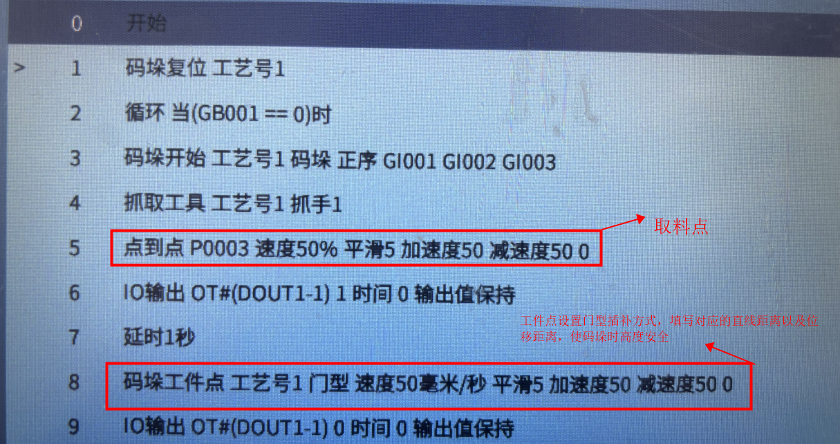
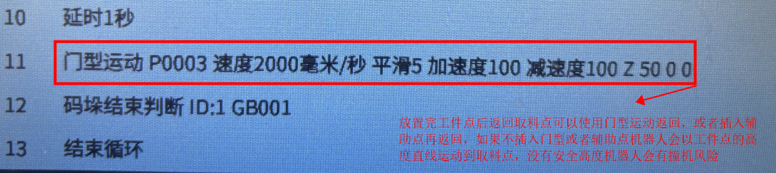
Palletizing actual application can be achieved through two-point actual palletizing run (pickup point ------ workpiece point), as shown:
Usage Scenarios
Scenario 1 - Fixed Pickup Point, Layer-by-Layer Placement
Parameter Setting
- Click right side [Craft - Palletizing Process - Complete Palletizing].
- Select craft number based on actual situation. Here select craft number 1.
- Click gripper settings.
- Select gripper based on actual situation. Here select gripper count 1, gripper tool number 1 (gripper tool number is tool hand number. Gripper needs to be set in [Settings - Robot Parameters - Tool Hand Calibration] interface first). Can only select here, click save.
- Click next page to enter pallet settings (can also click return navigation to enter pallet settings).
- Calibrate pallet coordinate system (user coordinate system) based on actual pallet. Click save. Note: Need to calibrate with tool hand when calibrating pallet. Calibrated coordinate system Z axis cannot face down.
- Click next page to enter position settings (can also click return navigation to enter position settings).
- Calibrate workpiece point, auxiliary point, entry point based on actual situation. Click save. Note: Need to calibrate with tool hand.
- Click next page to enter workpiece parameter settings (can also click return navigation to enter workpiece parameter settings).
- Fill workpiece size parameters based on actual situation. Here set length "50", width "30", height "15", gap 0. Click save.
- Click next page to enter approach parameter settings (can also click return navigation to enter approach parameter settings).
- Set based on actual situation. If not needed, skip directly.
- Click next page to enter overlap mode settings (can also click return navigation to enter overlap mode).
- Fill layer count based on actual situation. Here set layer count to "10", repeat relationship to "Same", first layer pattern number to "1", other parameters not filled. Click save.
- Click next page to enter plane mode settings (can also click return navigation to enter plane mode).
- Select pattern number "1", template "Cross-Stack", X direction count "1", Y direction count "3", other parameters default not filled. Click save. Click preview to view the set pattern template. Note: Overall rotation is 180 degrees around the first workpiece center.
- Click end to complete parameter settings.
Write Program
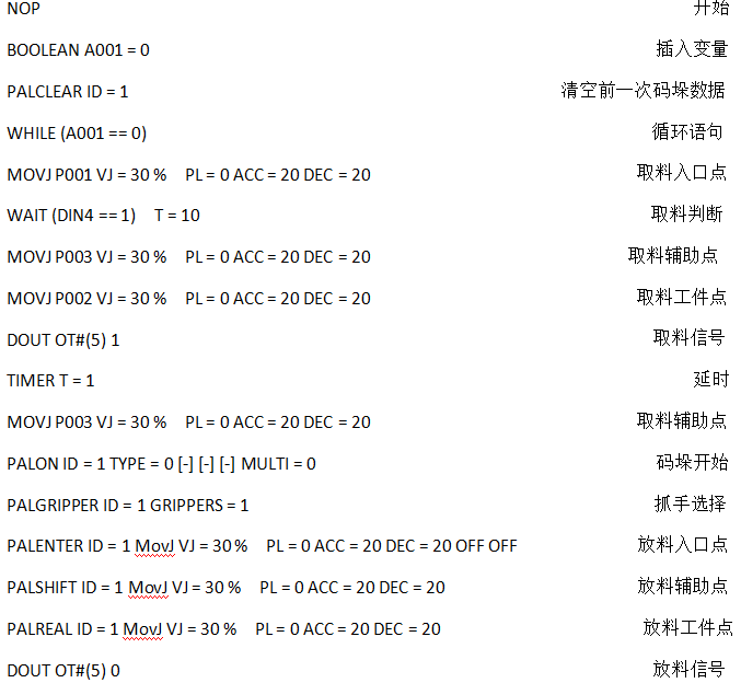
NOP //Start
BOOLEAN A001 = 0 //Insert variable
PALCLEAR ID = 1 //Clear previous palletizing data
WHILE (A001 == 0) //Loop statement
MOVJ P001 VJ = 30 % PL = 0 ACC = 20 DEC = 20 //Pickup entry point
WAIT (DIN4 == 1) T = 10 //Pickup judgment
MOVJ P003 VJ = 30 % PL = 0 ACC = 20 DEC = 20 //Pickup auxiliary point
MOVJ P002 VJ = 30 % PL = 0 ACC = 20 DEC = 20 //Pickup workpiece point
DOUT OT#(5) 1 //Pickup signal
TIMER T = 1 //Delay
MOVJ P003 VJ = 30 % PL = 0 ACC = 20 DEC = 20 //Pickup auxiliary point
PALON ID = 1 TYPE = 0 [-] [-] [-] MULTI = 0 //Palletizing start
PALGRIPPER ID = 1 GRIPPERS = 1 //Gripper selection
PALENTER ID = 1 MovJ VJ = 30 % PL = 0 ACC = 20 DEC = 20 OFF OFF //Placement entry point
PALSHIFT ID = 1 MovJ VJ = 30 % PL = 0 ACC = 20 DEC = 20 //Placement auxiliary point
PALREAL ID = 1 MovJ VJ = 30 % PL = 0 ACC = 20 DEC = 20 //Placement workpiece point
DOUT OT#(5) 0 //Placement signal
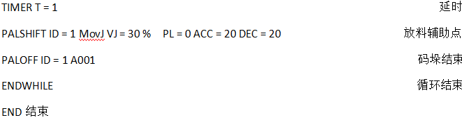
TIMER T = 1 //Delay
PALSHIFT ID = 1 MovJ VJ = 30 % PL = 0 ACC = 20 DEC = 20 //Placement auxiliary point
PALOFF ID = 1 A001 //Palletizing end
ENDWHILE //Loop end
END //End
Scenario 2 - Fixed Pickup Point, Placement Height Compensation
Parameter Setting
Open [Craft - Palletizing Process - Complete Palletizing - Overlap Mode], fill placement height compensation "100", click save.
Other parameter setting steps refer to Scenario 1.
Write Program
Note: Fill relevant parameters based on actual situation.
NOP //Start
BOOLEAN A001 = 0 //Insert variable
PALCLEAR ID = 1 //Clear previous palletizing data
WHILE (A001 == 0) //Loop statement
MOVJ P001 VJ = 30 % PL = 0 ACC = 20 DEC = 20 //Pickup entry point
WAIT (DIN4 == 1) T = 10 //Pickup judgment
MOVJ P003 VJ = 30 % PL = 0 ACC = 20 DEC = 20 //Pickup auxiliary point
MOVJ P002 VJ = 30 % PL = 0 ACC = 20 DEC = 20 //Pickup workpiece point
DOUT OT#(5) 1 //Pickup signal
TIMER T = 1 //Delay
MOVJ P003 VJ = 30 % PL = 0 ACC = 20 DEC = 20 //Pickup auxiliary point
PALON ID = 1 TYPE = 0 [-] [-] [-] MULTI = 0 //Palletizing start
PALGRIPPER ID = 1 GRIPPERS = 1 //Gripper selection
PALENTER ID = 1 MovJ VJ = 30 % PL = 0 ACC = 20 DEC = 20 OFF OFF //Placement entry point
PALSHIFT ID = 1 MovJ VJ = 30 % PL = 0 ACC = 20 DEC = 20 //Placement auxiliary point
PALREAL ID = 1 MovJ VJ = 30 % PL = 0 ACC = 20 DEC = 20 //Placement workpiece point
DOUT OT#(5) 0 //Placement signal
TIMER T = 1 //Delay
PALSHIFT ID = 1 MovJ VJ = 30 % PL = 0 ACC = 20 DEC = 20 //Placement auxiliary point
PALOFF ID = 1 A001 //Palletizing end
ENDWHILE //Loop end
END //End
Scenario 3 - Fixed Pickup Point, Layer Height Correction
Parameter Setting
Open [Craft - Palletizing Process - Complete Palletizing - Overlap Mode], fill each layer's height correction "50", click save.
Write Program
NOP //Start
BOOLEAN A001 = 0 //Insert variable
PALCLEAR ID = 1 //Clear previous palletizing data
WHILE (A001 == 0) //Loop statement
MOVJ P001 VJ = 30 % PL = 0 ACC = 20 DEC = 20 //Pickup entry point
WAIT (DIN4 == 1) T = 10 //Pickup judgment
MOVJ P003 VJ = 30 % PL = 0 ACC = 20 DEC = 20 //Pickup auxiliary point
MOVJ P002 VJ = 30 % PL = 0 ACC = 20 DEC = 20 //Pickup workpiece point
DOUT OT#(5) 1 //Pickup signal
TIMER T = 1 //Delay
MOVJ P003 VJ = 30 % PL = 0 ACC = 20 DEC = 20 //Pickup auxiliary point
PALON ID = 1 TYPE = 0 [-] [-] [-] MULTI = 0 //Palletizing start
PALGRIPPER ID = 1 GRIPPERS = 1 //Gripper selection
PALENTER ID = 1 MovJ VJ = 30 % PL = 0 ACC = 20 DEC = 20 OFF OFF //Placement entry point
PALSHIFT ID = 1 MovJ VJ = 30 % PL = 0 ACC = 20 DEC = 20 //Placement auxiliary point
PALREAL ID = 1 MovJ VJ = 30 % PL = 0 ACC = 20 DEC = 20 //Placement workpiece point
DOUT OT#(5) 0 //Placement signal
TIMER T = 1 //Delay
PALSHIFT ID = 1 MovJ VJ = 30 % PL = 0 ACC = 20 DEC = 20 //Placement auxiliary point
PALOFF ID = 1 A001 //Palletizing end
ENDWHILE //Loop end
END //End
Scenario 4 - Fixed Pickup Point, Fixed Placement Height, Vertical Direction Arrangement
Parameter Setting
Open [Craft - Palletizing Process - Complete Palletizing - Overlap Mode], check vertical direction arrangement, click save.
Note: When using vertical direction arrangement, repeat relationship needs to be changed to "Same". After clicking "vertical direction arrangement" button, repeat relationship automatically changes to "Same".
Write Program
NOP //Start
BOOLEAN A001 = 0 //Insert variable
PALCLEAR ID = 1 //Clear previous palletizing data
WHILE (A001 == 0) //Loop statement
MOVJ P001 VJ = 30 % PL = 0 ACC = 20 DEC = 20 //Pickup entry point
WAIT (DIN4 == 1) T = 10 //Pickup judgment
MOVJ P003 VJ = 30 % PL = 0 ACC = 20 DEC = 20 //Pickup auxiliary point
MOVJ P002 VJ = 30 % PL = 0 ACC = 20 DEC = 20 //Pickup workpiece point
DOUT OT#(5) 1 //Pickup signal
TIMER T = 1 //Delay
MOVJ P003 VJ = 30 % PL = 0 ACC = 20 DEC = 20 //Pickup auxiliary point
PALON ID = 1 TYPE = 0 [-] [-] [-] MULTI = 0 //Palletizing start
PALGRIPPER ID = 1 GRIPPERS = 1 //Gripper selection
PALENTER ID = 1 MovJ VJ = 30 % PL = 0 ACC = 20 DEC = 20 OFF OFF //Placement entry point
PALSHIFT ID = 1 MovJ VJ = 30 % PL = 0 ACC = 20 DEC = 20 //Placement auxiliary point
PALREAL ID = 1 MovJ VJ = 30 % PL = 0 ACC = 20 DEC = 20 //Placement workpiece point
DOUT OT#(5) 0 //Placement signal
TIMER T = 1 //Delay
PALSHIFT ID = 1 MovJ VJ = 30 % PL = 0 ACC = 20 DEC = 20 //Placement auxiliary point
PALOFF ID = 1 A001 //Palletizing end
ENDWHILE //Loop end
END //End
Scenario 5 - Fixed Pickup Point, Placement Point Overall Rotation 180°, XY Translation Compensation
Parameter Setting
- Open [Craft - Palletizing Process - Complete Palletizing - Overlap Mode].
- Fill layer count based on actual situation. Here set layer count to "10", repeat relationship to "Alternate", first layer pattern number to "1", second layer pattern number to "2", other parameters not filled. Click save.
- Open [Craft - Palletizing Process - Complete Palletizing - Plane Mode].
- Select pattern number "2", template "Cross-Stack", X direction count "1", Y direction count "3", overall rotation angle "180", X translation compensation "50", Y translation compensation "100", other parameters default not filled. Click save. Click preview to view the set pattern template.
Write Program
NOP //Start
BOOLEAN A001 = 0 //Insert variable
PALCLEAR ID = 1 //Clear previous palletizing data
WHILE (A001 == 0) //Loop statement
MOVJ P001 VJ = 30 % PL = 0 ACC = 20 DEC = 20 //Pickup entry point
WAIT (DIN4 == 1) T = 10 //Pickup judgment
MOVJ P003 VJ = 30 % PL = 0 ACC = 20 DEC = 20 //Pickup auxiliary point
MOVJ P002 VJ = 30 % PL = 0 ACC = 20 DEC = 20 //Pickup workpiece point
DOUT OT#(5) 1 //Pickup signal
TIMER T = 1 //Delay
MOVJ P003 VJ = 30 % PL = 0 ACC = 20 DEC = 20 //Pickup auxiliary point
PALON ID = 1 TYPE = 0 [-] [-] [-] MULTI = 0 //Palletizing start
PALGRIPPER ID = 1 GRIPPERS = 1 //Gripper selection
PALENTER ID = 1 MovJ VJ = 30 % PL = 0 ACC = 20 DEC = 20 OFF OFF //Placement entry point
PALSHIFT ID = 1 MovJ VJ = 30 % PL = 0 ACC = 20 DEC = 20 //Placement auxiliary point
PALREAL ID = 1 MovJ VJ = 30 % PL = 0 ACC = 20 DEC = 20 //Placement workpiece point
DOUT OT#(5) 0 //Placement signal
TIMER T = 1 //Delay
PALSHIFT ID = 1 MovJ VJ = 30 % PL = 0 ACC = 20 DEC = 20 //Placement auxiliary point
PALOFF ID = 1 A001 //Palletizing end
ENDWHILE //Loop end
END //End
Scenario 6 - Fixed Pickup Point, Placement Point Workpiece Rotation 90°
Parameter Setting
- Open [Craft - Palletizing Process - Complete Palletizing - Overlap Mode].
- Fill layer count based on actual situation. Here set layer count to "10", repeat relationship to "Same", first layer pattern number to "3", other parameters not filled. Click save.
- Open [Craft - Palletizing Process - Complete Palletizing - Plane Mode].
- Select pattern number "3", template "Row-Column", X direction count "2", Y direction count "3", workpiece rotation angle "90", other parameters default not filled. Click save. Click preview to view the set pattern template.
Write Program
NOP //Start
BOOLEAN A001 = 0 //Insert variable
PALCLEAR ID = 1 //Clear previous palletizing data
WHILE (A001 == 0) //Loop statement
MOVJ P001 VJ = 30 % PL = 0 ACC = 20 DEC = 20 //Pickup entry point
WAIT (DIN4 == 1) T = 10 //Pickup judgment
MOVJ P003 VJ = 30 % PL = 0 ACC = 20 DEC = 20 //Pickup auxiliary point
MOVJ P002 VJ = 30 % PL = 0 ACC = 20 DEC = 20 //Pickup workpiece point
DOUT OT#(5) 1 //Pickup signal
TIMER T = 1 //Delay
MOVJ P003 VJ = 30 % PL = 0 ACC = 20 DEC = 20 //Pickup auxiliary point
PALON ID = 1 TYPE = 0 [-] [-] [-] MULTI = 0 //Palletizing start
PALGRIPPER ID = 1 GRIPPERS = 1 //Gripper selection
PALENTER ID = 1 MovJ VJ = 30 % PL = 0 ACC = 20 DEC = 20 OFF OFF //Placement entry point
PALSHIFT ID = 1 MovJ VJ = 30 % PL = 0 ACC = 20 DEC = 20 //Placement auxiliary point
PALREAL ID = 1 MovJ VJ = 30 % PL = 0 ACC = 20 DEC = 20 //Placement workpiece point
DOUT OT#(5) 0 //Placement signal
TIMER T = 1 //Delay
PALSHIFT ID = 1 MovJ VJ = 30 % PL = 0 ACC = 20 DEC = 20 //Placement auxiliary point
PALOFF ID = 1 A001 //Palletizing end
ENDWHILE //Loop end
END //End
Scenario 7 - Fixed Pickup Point, Fixed Auxiliary Point Height
Parameter Setting
- Open [Craft - Palletizing Process - Complete Palletizing - Overlap Mode].
- Fill layer count based on actual situation. Here set layer count to "3", repeat relationship to "Same", first layer pattern number to "1", turn on fixed auxiliary point button, layer auto-align, attitude auto-rotate. Click save.
- Open [Craft - Palletizing Process - Complete Palletizing - Plane Mode].
- Select pattern number "1", template "Row-Column", X direction count "3", Y direction count "4", other parameters default not filled. Click save. Click preview to view the set pattern template.
Write Program
Scenario 8 - Depalletizing
Parameter Setting
- Click right side [Craft - Palletizing Process - Complete Palletizing].
- Select craft number based on actual situation. Here select craft number 1.
- Click gripper settings.
- Select gripper based on actual situation. Here select gripper count 1, gripper tool number 1 (gripper tool number is tool hand number. Gripper needs to be set in [Settings - Robot Parameters - Tool Hand Calibration] interface first). Can only select here, not calibrate. Click save.
- Click next page to enter pallet settings (can also click return navigation to enter pallet settings).
- Calibrate pallet coordinate system (user coordinate system) based on actual pallet. Click save. Note: Need to calibrate with tool hand when calibrating pallet. Calibrated coordinate system Z axis cannot face down.
- Click next page to enter position settings (can also click return navigation to enter position settings).
- Calibrate workpiece point, auxiliary point, entry point based on actual situation. Click save. Note: Need to calibrate with tool hand. Depalletizing workpiece point is still calibrated according to palletizing. Depalletizing starts from the last workpiece of the highest layer.
- Click next page to enter workpiece parameter settings (can also click return navigation to enter workpiece parameter settings).
- Fill workpiece size parameters based on actual situation. Here set length "50", width "30", height "15", gap 0. Click save.
- Click next page to enter approach parameter settings (can also click return navigation to enter approach parameter settings).
- Set based on actual situation. If not needed, skip directly.
- Click next page to enter overlap mode settings (can also click return navigation to enter overlap mode).
- Fill layer count based on actual situation. Here set layer count to "10", repeat relationship to "Same", first layer pattern number to "1", other parameters not filled. Click save.
- Click next page to enter plane mode settings (can also click return navigation to enter plane mode).
- Select pattern number "1", template "Cross-Stack", X direction count "1", Y direction count "3", other parameters default not filled. Click save. Click preview to view the set pattern template. Note: Overall rotation is 180 degrees around the first workpiece center.
- Click end to complete craft number 1 parameter settings.
Write Program
NOP //Start
BOOLEAN A001 = 0 //Insert variable
PALCLEAR ID = 1 //Clear previous palletizing data
WHILE (A001 == 0) //Loop statement
PALON ID = 1 TYPE = 1 [-] [-] [-] MULTI = 0 //Depalletizing start
PALGRIPPER ID = 1 GRIPPERS = 1 //Select gripper
PALENTER ID = 1 MovJ VJ = 20 % PL = 0 ACC = 20 DEC = 20 OFF OFF //Pickup entry point
WAIT (DIN4 == 1) T = 10 //Pickup judgment
PALSHIFT ID = 1 MovJ VJ = 20 % PL = 0 ACC = 20 DEC = 20 //Pickup auxiliary point
PALREAL ID = 1 MovJ VJ = 20 % PL = 0 ACC = 20 DEC = 20 //Pickup workpiece point
DOUT OT#(5) 1 //Pickup signal
TIMER T = 1 //Delay
PALSHIFT ID = 1 MovJ VJ = 20 % PL = 0 ACC = 20 DEC = 20 //Pickup auxiliary point
PALOFF ID = 1 A001 //Depalletizing end
MOVJ P001 VJ = 30 % PL = 0 ACC = 20 DEC = 20 //Placement entry point
MOVJ P003 VJ = 30 % PL = 0 ACC = 20 DEC = 20 //Placement auxiliary point
MOVJ P002 VJ = 30 % PL = 0 ACC = 20 DEC = 20 //Placement workpiece point
DOUT OT#(5) 0 //Placement signal
TIMER T = 1 //Delay
MOVJ P003 VJ = 30 % PL = 0 ACC = 20 DEC = 20 //Placement auxiliary point
ENDWHILE //Loop end
END //End
Scenario 9 - Palletizing After Depalletizing
Parameter Setting
- Depalletizing Parameters
- Click right side [Craft - Palletizing Process - Complete Palletizing].
- Select craft number based on actual situation. Here select craft number 1.
- Click gripper settings.
- Select gripper based on actual situation. Here select gripper count 1, gripper tool number 1 (gripper tool number is tool hand number. Gripper needs to be set in [Settings - Robot - Tool Hand Calibration] interface first). Can only select here, click save.
- Click next page to enter pallet settings (can also click return navigation to enter pallet settings).
- Calibrate pallet coordinate system (user coordinate system) based on actual pallet. Click save. Note: Need to calibrate with tool hand when calibrating pallet. Calibrated coordinate system Z axis cannot face down.
- Click next page to enter position settings (can also click return navigation to enter position settings).
- Calibrate workpiece point, auxiliary point, entry point based on actual situation. Click save. Note: Need to calibrate with tool hand. Depalletizing workpiece point is still calibrated according to palletizing. Depalletizing starts from the last workpiece of the highest layer.
- Click next page to enter workpiece parameter settings (can also click return navigation to enter workpiece parameter settings).
- Fill workpiece size parameters based on actual situation. Here set length "50", width "30", height "15", gap 0. Click save.
- Click next page to enter approach parameter settings (can also click return navigation to enter approach parameter settings).
- Set based on actual situation. If not needed, skip directly.
- Click next page to enter overlap mode settings (can also click return navigation to enter overlap mode).
- Fill layer count based on actual situation. Here set layer count to "10", repeat relationship to "Same", first layer pattern number to "1", other parameters not filled. Click save.
- Click next page to enter plane mode settings (can also click return navigation to enter plane mode).
- Select pattern number "1", template "Cross-Stack", X direction count "1", Y direction count "3", other parameters default not filled. Click save. Click preview to view the set pattern template. Note: Overall rotation is 180 degrees around the first workpiece center.
- Click end to complete craft number 1 parameter settings.
- Palletizing Parameters
- Click complete palletizing.
- Select craft number 2, fill craft number 2 parameters following craft number 1 steps.
Note: Depalletizing parameters are the same as palletizing parameters.
Write Program
NOP //Start
BOOLEAN A001 = 0 //Insert variable
BOOLEAN A002 = 0 //Insert variable
PALCLEAR ID = 1 //Clear previous depalletizing data
PALCLEAR ID = 2 //Clear previous palletizing data
WHILE (A001 == 0) //Loop statement
PALON ID = 1 TYPE = 1 [-] [-] [-] MULTI = 0 //Depalletizing start
PALGRIPPER ID = 1 GRIPPERS = 1 //Select gripper
PALENTER ID = 1 MovJ VJ = 20 % PL = 0 ACC = 20 DEC = 20 OFF OFF //Pickup entry point
WAIT (DIN4 == 1) T = 10 //Pickup judgment
PALSHIFT ID = 1 MovJ VJ = 20 % PL = 0 ACC = 20 DEC = 20 //Pickup auxiliary point
PALREAL ID = 1 MovJ VJ = 20 % PL = 0 ACC = 20 DEC = 20 //Pickup workpiece point
DOUT OT#(5) 1 //Pickup signal
TIMER T = 1 //Delay
PALSHIFT ID = 1 MovJ VJ = 20 % PL = 0 ACC = 20 DEC = 20 //Pickup auxiliary point
PALOFF ID = 1 //Depalletizing end
PALON ID = 2 TYPE = 0 [-] [-] [-] MULTI = 0 //Palletizing start
PALGRIPPER ID = 2 GRIPPERS = 1 //Select gripper
PALENTER ID = 2 MovJ VJ = 30 % PL = 0 ACC = 20 DEC = 20 OFF OFF //Placement entry point
PALSHIFT ID = 2 MovJ VJ = 30 % PL = 0 ACC = 20 DEC = 20 //Placement auxiliary point
PALREAL ID = 2 MovJ VJ = 30 % PL = 0 ACC = 20 DEC = 20 //Placement workpiece point
DOUT OT#(5) 0 //Placement signal
TIMER T = 1 //Delay
PALSHIFT ID = 2 MovJ VJ = 30 % PL = 0 ACC = 20 DEC = 20 //Placement auxiliary point
PALOFF ID = 2 A001 //Palletizing end
ENDWHILE //Loop end
Scenario 10 - Palletizing Interrupted, Continue Palletizing
Parameter Setting
- Craft parameter setting before palletizing starts.
- Craft parameter setting after interruption.
- Open [Status - Palletizing Status].
- Craft number selects the craft number set in craft parameter setting. Here select previously set craft number 1.
- If previously set to have palletized to layer 1 workpiece 5.
- Then fill current layer "1", current layer palletized workpiece count "5". Click save.
Write Program
NOP //Start
BOOLEAN A001 = 0 //Insert variable
PALCLEAR ID = 1 //Clear previous palletizing data
WHILE (A001 == 0) //Loop statement
MOVJ P001 VJ = 30 % PL = 0 ACC = 20 DEC = 20 //Pickup entry point
WAIT (DIN4 == 1) T = 10 //Pickup judgment
MOVJ P003 VJ = 30 % PL = 0 ACC = 20 DEC = 20 //Pickup auxiliary point
MOVJ P002 VJ = 30 % PL = 0 ACC = 20 DEC = 20 //Pickup workpiece point
DOUT OT#(5) 1 //Pickup signal
TIMER T = 1 //Delay
MOVJ P003 VJ = 30 % PL = 0 ACC = 20 DEC = 20 //Pickup auxiliary point
PALON ID = 1 TYPE = 0 [-] [-] [-] MULTI = 0 //Palletizing start
PALGRIPPER ID = 1 GRIPPERS = 1 //Gripper selection
PALENTER ID = 1 MovJ VJ = 30 % PL = 0 ACC = 20 DEC = 20 OFF OFF //Placement entry point
PALSHIFT ID = 1 MovJ VJ = 30 % PL = 0 ACC = 20 DEC = 20 //Placement auxiliary point
PALREAL ID = 1 MovJ VJ = 30 % PL = 0 ACC = 20 DEC = 20 //Placement workpiece point
DOUT OT#(5) 0 //Placement signal
TIMER T = 1 //Delay
PALSHIFT ID = 1 MovJ VJ = 30 % PL = 0 ACC = 20 DEC = 20 //Placement auxiliary point
PALOFF ID = 1 A001 //Palletizing end
ENDWHILE //Loop end
END //End
Scenario 11 - Multi-Gripper Cooperative Palletizing
Parameter Setting
- Click right side [Craft - Palletizing Process - Complete Palletizing].
- Select craft number based on actual situation. Here select craft number 1.
- Click gripper settings.
- Select gripper based on actual situation. Here select gripper count "4", gripper 1 tool number "2", gripper 2 tool number "4", gripper 3 tool number "5", gripper 4 tool number "1" (gripper tool number is tool hand number. Gripper needs to be set in [Settings - Tool Hand Calibration] interface first). Can only select here, click save.
- Click next page to enter pallet settings (can also click return navigation to enter pallet settings).
- Calibrate pallet coordinate system (user coordinate system) based on actual pallet. Click save (Note: Need to calibrate with tool hand when calibrating pallet -- can calibrate with any gripper. Calibrated coordinate system Z axis cannot face down).
- Click next page to enter position settings (can also click return navigation to enter position settings).
- Calibrate workpiece point, auxiliary point, entry point based on actual situation. Click save (Note: Need to calibrate with tool hand).
- Click next page to enter workpiece parameter settings (can also click return navigation to enter workpiece parameter settings).
- Fill workpiece size parameters based on actual situation. Here set length "50", width "30", height "15", gap 0. Click save.
- Click next page to enter approach parameter settings (can also click return navigation to enter approach parameter settings. Set based on actual situation. If not needed, skip directly).
- Click next page to enter overlap mode settings (can also click return navigation to enter overlap mode).
- Fill layer count based on actual situation. Here set layer count to "10", repeat relationship to "Same", first layer pattern number to "1", other parameters not filled. Click save.
- Click next page to enter plane mode settings (can also click return navigation to enter plane mode).
- Select pattern number "1", template "Cross-Stack", X direction count "1", Y direction count "3", other parameters default not filled. Click save. Click preview to view the set pattern template (Note: Overall rotation is 180 degrees around the first workpiece center).
- Click end to complete parameter settings.
Write Program
NOP //Start
PALCLEAR ID = 1 //Palletizing reset
WHILE {(GB001 == 0)} //Loop statement
MOVJ P0001 VJ = 50 % PL = 0 ACC = 50 DEC = 50 0 //Pickup safety point
MOVJ P0002 VJ = 50 % PL = 0 ACC = 50 DEC = 50 0 //Pickup above point
MOVJ P0003 VJ = 50 % PL = 0 ACC = 50 DEC = 50 0 //Pickup point
DOUT OT#(1) 1 T = 0 0 //Pickup signal
TIMER T = 1 //Delay 1 second
MOVJ P0002 VJ = 50 % PL = 0 ACC = 50 DEC = 50 0 //Pickup above point
PALON ID = 1 TYPE = 0 GI001 GI002 GI003 MULTI = 0 //Palletizing start
SWITCHTOOL (1) //Switch tool coordinate 1
PALGRIPPER ID = 1 GRIPPERS = 1 //Switch gripper tool 1
PALSHIFT ID = 1 MOVJ VJ = 50 % PL = 0 ACC = 20 DEC = 20 0 //Palletizing auxiliary point
PALREAL ID = 1 MOVJ VJ = 50 % PL = 0 ACC = 20 DEC = 20 0 //Palletizing workpiece point
DOUT OT#(1) 0 T = 0 0 //Placement signal
TIMER T = 1 //Delay 1 second
PALSHIFT ID = 1 MOVJ VJ = 50 % PL = 0 ACC = 20 DEC = 20 0 //Palletizing auxiliary point
PALOFF ID = 1 GB001 //Palletizing end judgment
PALON ID = 1 TYPE = 0 GI001 GI002 GI003 MULTI = 0 //Palletizing start
SWITCHTOOL (2) //Switch tool coordinate 2
PALGRIPPER ID = 1 GRIPPERS = 2 //Switch gripper tool 2
PALSHIFT ID = 1 MOVJ VJ = 50 % PL = 0 ACC = 20 DEC = 20 0 //Palletizing auxiliary point
PALREAL ID = 1 MOVJ VJ = 50 % PL = 0 ACC = 20 DEC = 20 0 //Palletizing workpiece point
DOUT OT#(1) 0 T = 0 0 //Placement signal
TIMER T = 1 //Delay 1 second
PALSHIFT ID = 1 MOVJ VJ = 50 % PL = 0 ACC = 20 DEC = 20 0 //Palletizing auxiliary point
PALOFF ID = 1 GB001 //Palletizing end judgment
ENDWHILE //End loop
END //End
Scenario 12(1) - One Line Two Stacks (Two stacks have same workpiece count)
Overview
Description: When approach enable is off, program will not generate palletizing approach point instruction (turning on enable does the opposite). Approach method has two types: approach descending and descending approach.
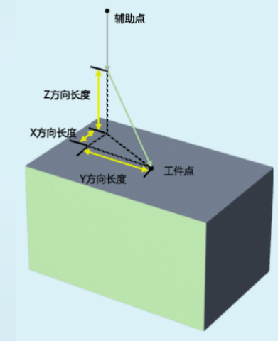
Approach Descending: For example: According to the set approach parameters, approach point position is 50 from workpiece point in X direction, 50 in Y direction, 50 in Z direction. Move from approach point to workpiece point using the set approach method.
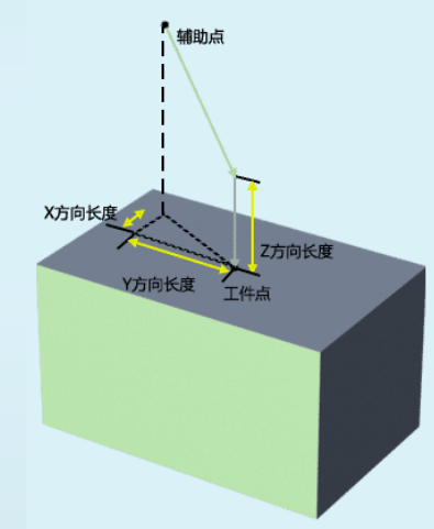
Descending Approach: For example: According to the set approach parameters, auxiliary point position is 50 from workpiece point in X direction, 50 in Y direction. Move from auxiliary point to approach point (50 above workpiece point) using the set approach method, then vertically descend from approach point to workpiece point.
Pallet Detection: Pallet total count setting range is [1-5]. Fixed bound IO ports are 2-1 to 2-5. Program automatically detects IO open/close to determine pallet count. For example, when pallet total is '3', pallet thickness is '10'mm. Starting program will auto-detect IO 2-1, 2-2, 2-3 open/close. When pallet count decreases by one (2-1 or 2-2 or 2-3 any one closes), all workpiece points' Z axis direction decreases by 10mm.
Parameter Setting
- Click [Craft - Palletizing Process - Palletizing Parameters - Complete Palletizing].
- Select craft number based on actual situation. Here first stack selects craft number 1.
- Click gripper settings. Select based on actual situation. For example: gripper count "1", gripper 1 tool number "1" (gripper tool number is tool hand number. Gripper needs to be set in [Settings - Robot Parameters - Tool Hand Calibration] interface first). Click save after modification.
- Click next page to enter pallet settings (can also click return navigation to enter pallet settings). Calibrate pallet coordinate system (user coordinate system) based on actual pallet. Select user coordinate system, first calibrate pallet origin, pallet X axis positive direction, pallet Y axis positive direction. After calibration must click calculate. Uncalibrated Z axis positive direction is automatically calculated by the system based on calibrated X, Y axis positive directions. Click save after all calibration (Note: Need to calibrate with tool hand when calibrating pallet -- can calibrate with any gripper. Calibrated coordinate system Z axis cannot face down).
- Click next page to enter position settings (can also click return navigation to enter position settings). Calibrate workpiece point, auxiliary point, entry point based on actual situation. Click save.
- Click next page to enter workpiece parameters. Set workpiece size based on actual situation. Here set length "50", width "50", height "50", gap 10 (Pallet Y positive direction is workpiece length, pallet X direction is workpiece width, pallet Z direction is workpiece height, gap is empty space between workpieces). Click save after filling.
- Click next page to enter approach parameter settings (can also click return navigation to enter approach parameter settings). Set approach method and pallet detection. Select based on actual situation whether to turn on. Here turn on approach enable switch and pallet detection switch. Pallet X direction length '50', pallet Y direction length '50', pallet Z direction length '50', pallet thickness '10', pallet total '3'.
- Click next page to enter overlap mode (can also click return navigation to enter overlap mode). Fill layer count based on actual situation. Here set layer count to '2', repeat relationship to 'Same', first layer pattern number "1", other parameters not filled (layer count is total workpiece layers, repeat relationship is each layer's arrangement relationship). Click save.
- Click next page to enter plane mode (can also click return navigation to enter plane mode). Select pattern number "1", template "Row-Column", X direction count "2", Y direction count "1", other parameters default not filled. Click save. Click preview to view the set pattern template (Note: Overall rotation is 180 degrees around the first workpiece center).
- Click end to complete parameter settings.
- Set the second stack following the above method based on actual situation. Craft number selects 2 (Note: User coordinate system in craft number 2 needs to be re-calibrated based on actual situation, or use the user coordinate system 1 set in craft number 1).
Write Program
NOP //Start
PALCLEAR ID = 1 //Palletizing reset craft number 1
PALCLEAR ID = 2 //Palletizing reset craft number 2
WHILE (B001 == 0) //Loop statement
PALON ID = 1 TYPE = 0 [-] [-] [-] MULTI = 0 //1 palletizing start
PALGRIPPER ID = 1 GRIPPERS = 1 //Gripper selection
MOVJ P001 VJ = 50 % PL = 5 ACC = 10 DEC = 10 0 //Pickup safety point
MOVJ P002 VJ = 50 % PL = 5 ACC = 10 DEC = 10 0 //Pickup above point
MOVJ P003 VJ = 50 % PL = 5 ACC = 10 DEC = 10 0 //Pickup point
DOUT OT#(1) 1 T = 0 0 //Pickup signal
TIMER T = 1 //Delay 1 second
MOVJ P002 VJ = 50 % PL = 5 ACC = 10 DEC = 10 0 //Pickup above point
PALENTER ID = 1 MovJ VJ = 50 % PL = 5 ACC = 10 DEC = 10 OFF OFF 0 //Placement entry point
PALSHIFT ID = 1 MovJ VJ = 50 % PL = 5 ACC = 10 DEC = 10 0 //Placement auxiliary point
PALAPPRO ID = 1 MovJ VJ = 50 % PL = 0 ACC = 20 DEC = 20 0 //Placement approach point
PALREAL ID = 1 MovJ VJ = 50 % PL = 5 ACC = 10 DEC = 10 0 //Placement workpiece point
DOUT OT#(1) 0 T = 0 0 //Placement signal
TIMER T = 1 //Delay 1s
PALAPPRO ID = 1 MovJ VJ = 50 % PL = 0 ACC = 20 DEC = 20 0 //Placement approach point
PALSHIFT ID = 1 MovJ VJ = 50 % PL = 5 ACC = 10 DEC = 10 0 //Placement auxiliary point
PALOFF ID = 1 //Palletizing end judgment
PALON ID = 2 TYPE = 0 [-] [-] [-] MULTI = 0 //2 palletizing start
PALGRIPPER ID = 2 GRIPPERS = 1 //Gripper selection
MOVJ P001 VJ = 50 % PL = 5 ACC = 10 DEC = 10 0 //Pickup safety point
MOVJ P002 VJ = 50 % PL = 5 ACC = 10 DEC = 10 0 //Pickup above point
MOVJ P003 VJ = 50 % PL = 5 ACC = 10 DEC = 10 0 //Pickup point
DOUT OT#(1) 1 T = 0 0 //Pickup signal
TIMER T = 1 //Delay 1 second
MOVJ P002 VJ = 50 % PL = 5 ACC = 10 DEC = 10 0 //Pickup above point
PALENTER ID = 2 MovJ VJ = 50 % PL = 5 ACC = 10 DEC = 10 OFF OFF 0 //Placement entry point
PALSHIFT ID = 2 MovJ VJ = 50 % PL = 5 ACC = 10 DEC = 10 0 //Placement auxiliary point
PALAPPRO ID = 1 MovJ VJ = 50 % PL = 0 ACC = 20 DEC = 20 0 //Placement approach point
PALREAL ID = 2 MovJ VJ = 50 % PL = 5 ACC = 10 DEC = 10 0 //Placement workpiece point
DOUT OT#(1) 0 T = 0 0 //Placement signal
TIMER T = 1 //Delay 1s
PALAPPRO ID = 1 MovJ VJ = 50 % PL = 0 ACC = 20 DEC = 20 0 //Placement approach point
PALSHIFT ID = 2 MovJ VJ = 50 % PL = 5 ACC = 10 DEC = 10 0 //Placement auxiliary point
PALOFF ID = 2 B001 //Palletizing craft number 2 and loop end judgment
ENDWHILE //End loop
END //End
Scenario 12(2) - One Line Two Stacks (Two stacks have different workpiece counts)
Description: When approach enable is off, program will not generate palletizing approach point instruction (turning on enable does the opposite). Approach method has two types: approach descending and descending approach.
Approach Descending: For example: According to the set approach parameters, approach point position is 50 from workpiece point in X direction, 50 in Y direction, 50 in Z direction. Move from approach point to workpiece point using the set approach method, as shown:
Descending Approach: For example: According to the set approach parameters, auxiliary point position is 50 from workpiece point in X direction, 50 in Y direction. Move from auxiliary point to approach point (50 above workpiece point) using the set approach method, then vertically descend from approach point to workpiece point.
Pallet Detection: Pallet total count setting range is [1-5]. Fixed bound IO ports are 2-1 to 2-5. Program automatically detects IO open/close to determine pallet count. For example, when pallet total is '3', pallet thickness is '10'mm. Starting program will auto-detect IO 2-1, 2-2, 2-3 open/close. When pallet count decreases by one (2-1 or 2-2 or 2-3 any one closes), all workpiece points' Z axis direction decreases by 10mm.
Parameter Setting
- Click [Craft - Palletizing Process - Palletizing Parameters - Complete Palletizing].
- Select craft number based on actual situation. Here first stack selects craft number 1.
- Click gripper settings. Select based on actual situation. For example: gripper count "1", gripper 1 tool number "1" (gripper tool number is tool hand number. Gripper needs to be set in [Settings - Robot Parameters - Tool Hand Calibration] interface first). Click save after modification.
- Click next page to enter pallet settings (can also click return navigation to enter pallet settings). Calibrate pallet coordinate system (user coordinate system) based on actual pallet. Select user coordinate system, first calibrate pallet origin, pallet X axis positive direction, pallet Y axis positive direction. After calibration must click calculate. Uncalibrated Z axis positive direction is automatically calculated by the system based on calibrated X, Y axis positive directions. Click save after all calibration (Note: Need to calibrate with tool hand when calibrating pallet -- can calibrate with any gripper. Calibrated coordinate system Z axis cannot face down).
- Click next page to enter position settings (can also click return navigation to enter position settings). Calibrate workpiece point, auxiliary point, entry point based on actual situation. Click save.
- Click next page to enter workpiece parameters. Set workpiece size based on actual situation. Here set length "50", width "50", height "50", gap 10 (Pallet Y positive direction is workpiece length, pallet X direction is workpiece width, pallet Z direction is workpiece height, gap is empty space between workpieces). Click save after filling.
- Click next page to enter approach parameter settings (can also click return navigation to enter approach parameter settings). Set approach method and pallet detection. Select based on actual situation whether to turn on. Here turn on approach enable switch and pallet detection switch. Pallet X direction length '50', pallet Y direction length '50', pallet Z direction length '50', pallet thickness '10', pallet total '3'.
- Click next page to enter overlap mode (can also click return navigation to enter overlap mode). Fill layer count based on actual situation. Here set layer count to '2', repeat relationship to 'Same', first layer pattern number "1", other parameters not filled (layer count is total workpiece layers, repeat relationship is each layer's arrangement relationship). Click save.
- Click next page to enter plane mode (can also click return navigation to enter plane mode). Select pattern number "1", template "Row-Column", X direction count "2", Y direction count "1", other parameters default not filled. Click save. Click preview to view the set pattern template (Note: Overall rotation is 180 degrees around the first workpiece center).
- Click end to complete parameter settings.
- Set the second stack following the above method based on actual situation. Craft number selects 2 (Note: User coordinate system in craft number 2 needs to be re-calibrated based on actual situation, or use the user coordinate system 1 set in craft number 1).
Write Program
NOP //Start
PALCLEAR ID = 1 //Palletizing reset craft number 1
PALCLEAR ID = 2 //Palletizing reset craft number 2
WHILE {(B003 == 0)} //Loop statement
IF {(B001 == 0)} //Execute stack 1 if judgment
PALON ID = 1 TYPE = 0 [-] [-] [-] MULTI = 0 //1 palletizing start
PALGRIPPER ID = 1 GRIPPERS = 1 //Gripper selection
MOVJ P001 VJ = 50 % PL = 0 ACC = 20 DEC = 20 0 //Pickup safety point
MOVJ P002 VJ = 50 % PL = 0 ACC = 20 DEC = 20 0 //Pickup above point
MOVJ P003 VJ = 50 % PL = 0 ACC = 20 DEC = 20 0 //Pickup point
DOUT OT#(1) 1 T = 0 0 //Pickup signal
TIMER T = 1 //Delay 1 second
MOVJ P002 VJ = 50 % PL = 0 ACC = 20 DEC = 20 0 //Pickup above point
PALENTER ID = 1 MovJ VJ = 50 % PL = 0 ACC = 20 DEC = 20 OFF OFF 0 //Placement entry point
PALSHIFT ID = 1 MovJ VJ = 50 % PL = 0 ACC = 20 DEC = 20 0 //Placement auxiliary point
PALAPPRO ID = 1 MovJ VJ = 50 % PL = 0 ACC = 20 DEC = 20 0 //Placement approach point
PALREAL ID = 1 MovJ VJ = 50 % PL = 0 ACC = 20 DEC = 20 0 //Placement point
DOUT OT#(1) 0 T = 0 0 //Placement signal
TIMER T = 1 //Delay 1 second
PALAPPRO ID = 1 MovJ VJ = 50 % PL = 0 ACC = 20 DEC = 20 0 //Placement approach point
PALSHIFT ID = 1 MovJ VJ = 50 % PL = 0 ACC = 20 DEC = 20 0 //Placement auxiliary point
PALOFF ID = 1 B001 //1 palletizing end judgment
ENDIF //End if
IF {(B002 == 0)} //Execute stack 2 if judgment
PALON ID = 2 TYPE = 0 [-] [-] [-] MULTI = 0 //2 stack start
PALGRIPPER ID = 2 GRIPPERS = 1 //Gripper selection
MOVJ P001 VJ = 50 % PL = 0 ACC = 20 DEC = 20 0 //Pickup safety point
MOVJ P002 VJ = 50 % PL = 0 ACC = 20 DEC = 20 0 //Pickup above point
MOVJ P003 VJ = 50 % PL = 0 ACC = 20 DEC = 20 0 //Pickup point
DOUT OT#(1) 1 T = 0 0 //Pickup signal
TIMER T = 1 //Delay 1 second
MOVJ P002 VJ = 50 % PL = 0 ACC = 20 DEC = 20 0 //Pickup above point
PALENTER ID = 2 MovJ VJ = 50 % PL = 0 ACC = 20 DEC = 20 OFF OFF 0 //Placement entry point
PALSHIFT ID = 2 MovJ VJ = 50 % PL = 0 ACC = 20 DEC = 20 0 //Placement auxiliary point
PALAPPRO ID = 2 MovJ VJ = 50 % PL = 0 ACC = 20 DEC = 20 0 //Placement approach point
PALREAL ID = 2 MovJ VJ = 50 % PL = 0 ACC = 20 DEC = 20 0 //Placement point
DOUT OT#(1) 0 T = 0 0 //Placement signal
TIMER T = 1 //Delay 1 second
PALAPPRO ID = 2 MovJ VJ = 50 % PL = 0 ACC = 20 DEC = 20 0 //Placement approach point
PALSHIFT ID = 2 MovJ VJ = 50 % PL = 0 ACC = 20 DEC = 20 0 //Placement auxiliary point
PALOFF ID = 2 B002 //2 stack end judgment
ENDIF //End if
IF {(B001 == 1)} AND {(B002 == 1)} //Judge if stack 1 and stack 2 are both complete
SETBOOL B003 = 1 //Variable to exit loop
ENDIF //End if
ENDWHILE //End loop
END //End
Q&A for Retrieval
Q: What is palletizing process?
A: Palletizing process is a typical application of robots in food, beverage, logistics and other industries. With different grippers, it can achieve boxing and palletizing of finished products of various shapes in different industries.
Q: What types does palletizing process support?
A: Palletizing process supports three types: Complete Palletizing, Simple Palletizing, Mark Point Palletizing.
Q: What is complete palletizing?
A: Complete palletizing supports detailed parameter settings including gripper settings, pallet settings, workpiece parameters, approach parameters, overlap mode, position settings, and plane mode.
Q: What is simple palletizing?
A: Simple palletizing is a simplified palletizing mode with relatively simple parameter settings, suitable for simpler palletizing scenarios.
Q: What is mark point palletizing?
A: Mark point palletizing achieves palletizing through manually marking positions, suitable for irregular or special palletizing needs.
Q: How many craft numbers does palletizing process support?
A: Palletizing process supports 999999 craft number parameters.
Q: What is the principle of gripper settings?
A: If two suction cups pick/place separately, set as two grippers; if two suction cups pick/place simultaneously, set as one gripper.
Q: What repeat relationships does overlap mode have?
A: Overlap mode has three repeat relationships: Same (each layer uses same pattern template), Alternate (pattern templates alternate every two layers), Custom (each layer's pattern template set individually).
Q: What is fixed auxiliary point height?
A: Turning on fixed auxiliary point height button makes the first layer and second layer workpiece share the same auxiliary point position, not shifting in Z+ direction as palletizing layers increase.
Q: What is placement height compensation?
A: Placement height compensation sets all workpieces' placement point height offset. Positive value shifts in Z+ direction, negative value shifts in Z- direction.
Q: What is position debugging?
A: Position debugging is used to view and modify palletizing process's workpiece point positions, including workpiece points, auxiliary points, entry points, etc.
Q: What are additional parameters?
A: Additional parameters are located in the lower right corner of position debugging interface, including configuration settings and reference point settings, for optimizing palletizing process.
Q: What is the configuration value range?
A: Configuration value range is 0-8, including entry point, auxiliary point, workpiece point configurations.
Q: What options does reference point have?
A: Reference point has two options: Zero position (reference judgment based on zero position) and Current position (reference judgment based on current position).
Q: How to resolve position unreachable issue?
A: When position shows unreachable, can modify the corresponding workpiece's configuration value. For example, if entry point is unreachable, modify entry point configuration value.
Q: What is layer auto-align?
A: After selecting layer auto-align, each layer template is automatically aligned, automatically calculating X axis and Y axis offsets.
Q: What is attitude auto-rotate?
A: After selecting attitude auto-rotate, when tool hand cannot reach auxiliary point and placement point with a fixed attitude, it will auto-rotate tool hand attitude. This function only works when both auxiliary point and workpiece point use joint interpolation.
Q: What is fixed entry point position?
A: After fixing entry point position, every workpiece after picking will be at the same entry point. Z axis is optimized during entry point process.
Q: What pattern templates does plane mode have?
A: Plane mode pattern templates include: Row-Column, Cross-Stack, Spiral, Pinwheel, Custom.
Q: What is auto calculate?
A: Auto calculate generates a rectangular pallet based on pallet setting interface's calibrated user coordinate system. Automatically calculates how many workpieces can be placed in X and Y directions based on workpiece size.
Q: What is the difference in workpiece order between palletizing and depalletizing?
A: Workpiece order in palletizing parameter setting interface follows palletizing order. Depalletizing order is reversed.
Q: Can simple palletizing and complete palletizing use the same craft number?
A: Simple palletizing craft number should not use the same craft number as complete palletizing. Otherwise switching requires re-setting parameters.
Q: How to copy palletizing parameters?
A: In palletizing parameter interface, click [Copy Parameters] to copy the currently selected craft number's parameters to another craft number.
Q: How to clear palletizing parameters?
A: In palletizing parameter interface, click [Clear Parameters] to clear the currently selected craft number's parameters.
Q: What is vertical direction arrangement?
A: After selecting vertical direction arrangement, will complete one vertical column first before palletizing the next vertical column.
Q: What is fixed placement point height?
A: After selecting fixed placement point height, placement point height is the same for every layer during palletizing. Height is the marked workpiece point height. Only effective during palletizing.
Q: What is the difference between mark this point and run to this point?
A: Mark this point: Robot moves to position first then click mark. Run to this point: Move to already marked point, need to press DEADMAN button then click.
Q: What is the purpose of mark point layer?
A: Mark point layer sets which layer the current calibration workpiece point is located on. Saves the process of clearing the stack. Can directly select mark current layer.
Version History
| Version | Date | Changes | Author |
|---|---|---|---|
| 1.0.0 | 2026-07-01 | Initial version | FDJAK |