1 Welding Machine Settings
Welding machine settings need to be modified in "Craft/Welding Process/Welding Machine Settings".
Steps as follows:
Enter "Craft/Welding Process/Welding Machine Settings" page.
Two methods for controlling welding machine:
Analog Control: Full name is analog welding machine. Refers to welding machine controlled through IO analog quantities.
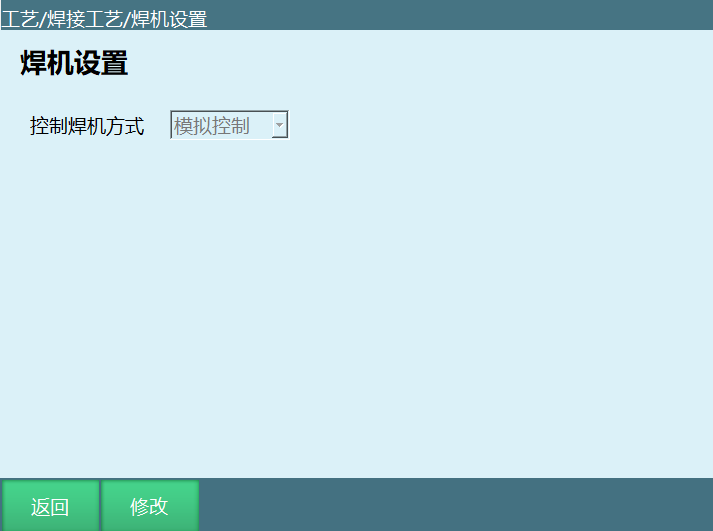
Digital Control: Set according to actual industrial site requirements.
Click modify to select welding machine control method:
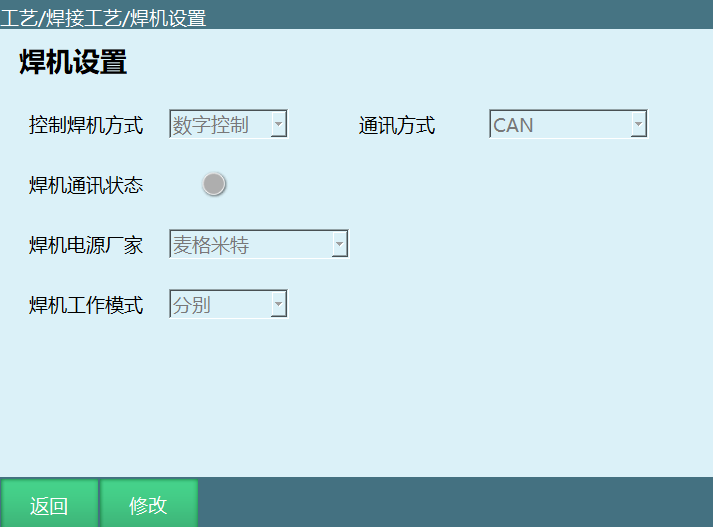
Four communication methods for digital welding machine: CAN, ModBus RTU, EtherCAT, ModBus TCP.
When selecting ModBus RTU, need to fill in slave ID, port number, baud rate.
When selecting ModBus TCP, need to fill in IP, port number.
Welding Communication Status: Gray indicates communication not successful. Green indicates communication successful.
Welding Power Supply Manufacturer: General, Megmeet, Shenwei Intelligent, Aotai, Mejennic, Riland.
When selecting Riland, need to fill in parameters in [Material/Wire Diameter/Gas].
Welding Machine Working Mode: Synergic, Separate.
Click save. Save successful.
2 Welding IO Settings
Welding IO settings need to be modified in "Craft/Welding Process/Welding IO Settings". Related steps as follows:
Enter "Craft/Welding Process/Welding IO Settings" page.
After clicking modify, the modify button changes to save. Can select corresponding IO ports behind each function.
2.1 Digital Input
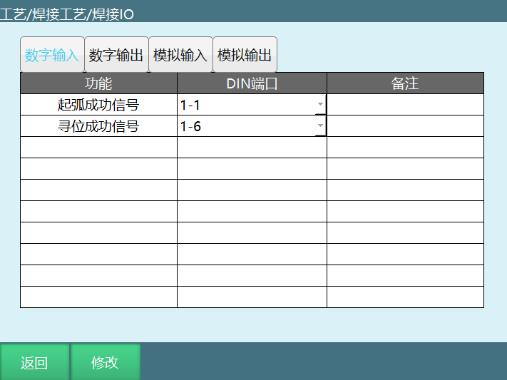
Arc Start Success Signal: Setting this signal is used to detect whether arc start was successful. When executing welding start instruction, need to give arc start signal. If arc start signal exceeds the set welding detection time, will report error (Welding arc start signal timeout).
Positioning Success Signal: In arc positioning, need to set positioning success signal (required signal can select port yourself).
Usage Method:
In arc positioning, find two single-core wires. One wire's one end connects to IO output port 1-5 (positioning mode signal), the other end connects to iron plate.
The other wire connects to IO input port 1-6 (positioning success signal), the other end connects to tool hand end.
In arc positioning, turn on output port 1-5. When tool hand end touches iron plate, the set 1-6 input signal changes from low level to high level.
2.2 Digital Output
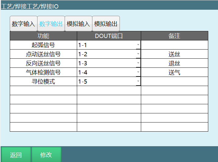
Arc Start Signal: When preparing to arc start, system will send output signal to welding machine.
Manual Wire Feed Signal: Welding machine feeds wire. When turning on corresponding signal port, welding monitoring window synchronously displays: Manual operation - Wire feed switch on.
Reverse Wire Feed Signal: When welding machine retracts wire, IO board gives corresponding output signal.
Gas Detection Signal: When gas pump supplies gas, IO board gives corresponding output signal.
Positioning Mode: Represents welding machine entering positioning mode. When robot moves and welding wire touches workpiece, welding machine gives positioning success signal.
Usage Method:
In arc positioning, find two single-core wires. One wire's one end connects to IO output port 1-5 (positioning mode signal), the other end connects to iron plate.
The other wire connects to IO input port 1-6 (positioning success signal), the other end connects to tool hand end.
In arc positioning, turn on output port 1-5. When tool hand end touches iron plate, the set 1-6 input signal port changes from low level to high level.
2.3 Analog Input
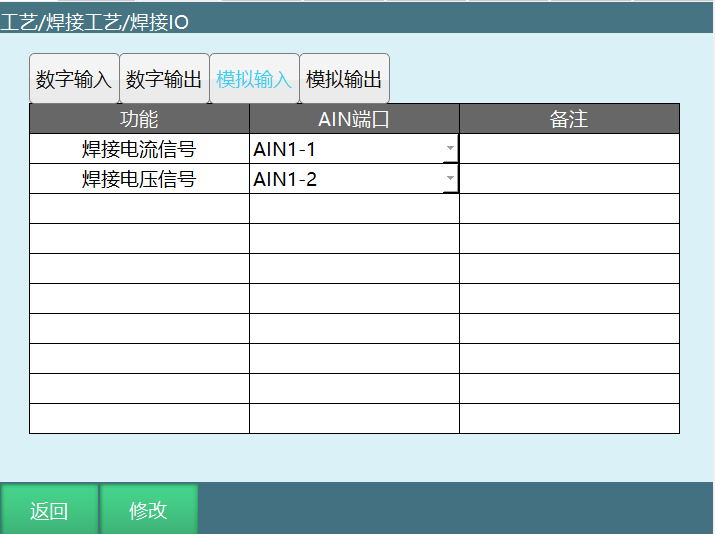
Welding Current Signal: Analog welding machine current input signal.
Welding Voltage Signal: Analog welding machine voltage input signal.
2.4 Analog Output
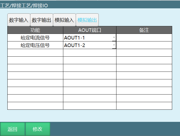
Given Current Signal: Signal for given current.
Given Voltage Signal: Signal for given voltage.
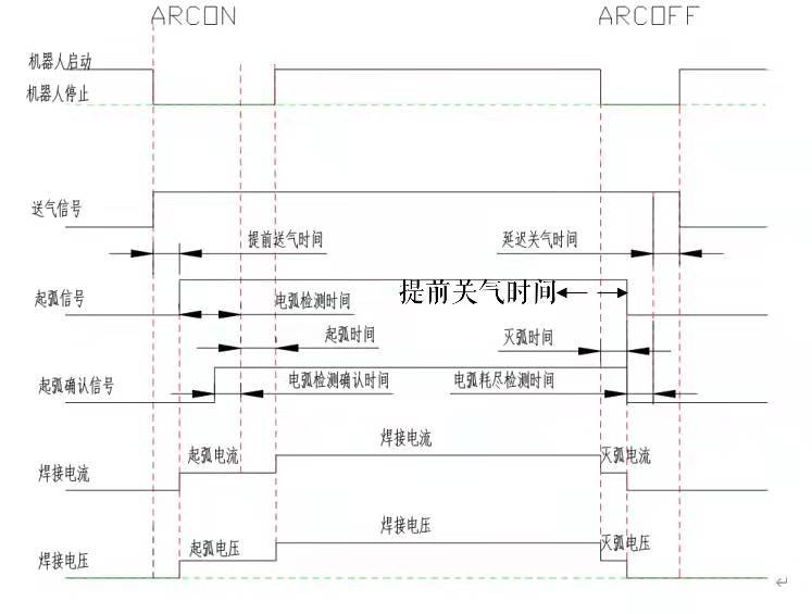
Welding sequence diagram as shown:
3 Current-Voltage Matching
Setting welding voltage and current needs to be modified in "Craft/Welding Process/Current-Voltage Matching". Related steps as follows:
- Enter "Craft/Welding Process/Current-Voltage Matching" page (Note: When selecting digital welding machine, this page is hidden).
At this time, current and voltage input boxes cannot input values. After clicking modify, the modify button changes to save. Can input values in each parameter field.
3.1 Current Control Matching Interface Parameter Setting Steps
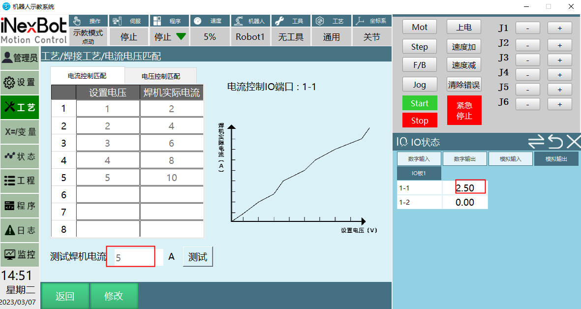
Connect controller and welding machine. Open teach pendant interface as shown above.
Set Voltage: Input voltage value.
Welding Machine Actual Current: Welding machine's actual output current, displayed on welding machine.
Test Welding Current: Fill in values in the set voltage column and welding actual current column. Input value in test welding current box, click test, will calculate a value.
This value is a scale coefficient calculated from the voltage and welding machine actual current values filled in above. The scale coefficient calculated from the values in the figure is 2.
At this time, test welding current is filled with 5A. After clicking test, the selected analog output port calculates current value 2.5 through scale coefficient.
Note: Welding machine current AOUT port output upper limit is 10. When greater than 10, executes at upper limit. When less than 0, executes at lower limit.
3.2 Voltage Control Matching Interface Parameter Setting Steps
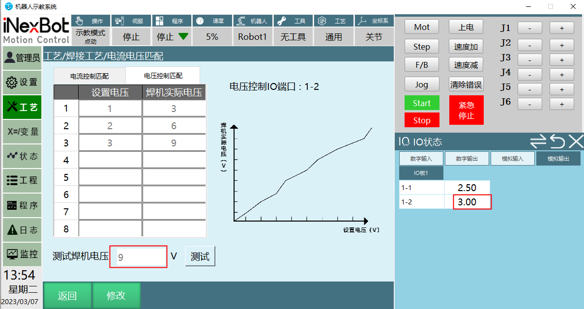
The function diagram shows the proportional relationship between voltage and current sent by controller to welding machine and welding machine's actual voltage and current.
Connect controller and welding machine. Open teach pendant interface as shown.
Set Voltage: Refers to the analog output value in IO monitoring.
Welding Machine Actual Voltage: Welding machine's actual output voltage, displayed on welding machine.
Test Welding Voltage: Fill in values in the set voltage column and welding actual voltage column. Input value in test welding voltage box, click test, will calculate a value.
This value is a scale coefficient calculated from the voltage and welding machine actual current values filled in the figure. The scale coefficient calculated from the values in the figure is 3.
At this time, test welding voltage is filled with 9V. After clicking test, the selected analog output port calculates voltage value 3 through scale coefficient.
Note: Welding machine voltage AOUT port output upper limit is 10. When greater than 10, executes at upper limit. When less than 0, executes at lower limit.
3.3 Current-Voltage Matching Operation Steps When Connecting Welding Machine
Current-voltage matching does multi-segment matching: Current-voltage matching is divided into multiple segments, can be 1~8 any number of segments.
Operation steps as follows:
Select current control matching.
Row 1 set voltage fill 1, check welding machine's current value now, fill the seen current value into row 1 welding machine actual current.
Row 2 set voltage fill 3, check welding machine's current value now, fill the seen current value into row 2 welding machine actual current.
Repeat above operation until 8 rows are filled (if only doing 1 segment matching, fill rows 1 and 2).
Test welding current fill 220, check if welding machine current is 220.
Click save. Modification successful. This function parameter saves 1 copy, no craft number.
3.4 Welding Parameter Settings
Setting welding parameters needs to be modified in "Craft/Welding Process/Welding Parameter Settings". Related steps as follows:
Enter "Craft/Welding Process/Welding Parameter Settings" page.
Click modify, the modify button changes to save. At this time, craft number can be selected. Arc start parameters, welding parameters, and arc end parameters can be modified.
For example: If arc start current=10, arc start voltage=8, welding current=15, welding voltage=20, arc end current=10, arc end voltage=15.
Turn on arc start gradient enable, set arc start gradient time 1 second, arc start gradient method select [Time Gradient].
Turn on arc end gradient enable, set arc end gradient time 1 second, arc end gradient method select [Time Gradient].
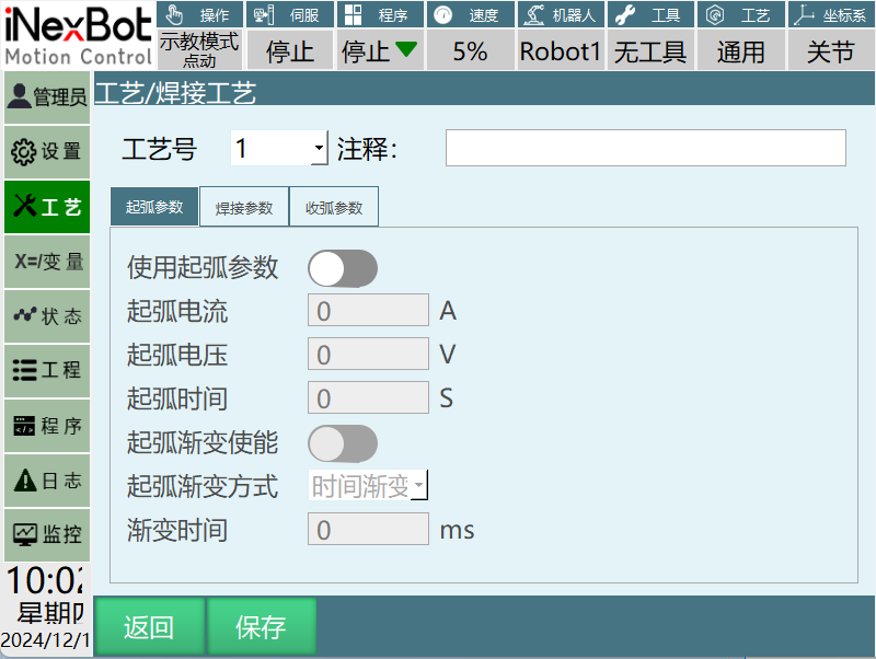
Craft Number: Welding wire has multiple options: carbon steel wire, low alloy structural steel wire, alloy structural steel wire, stainless steel wire, and non-ferrous metal wire. Different wires require different arc start voltage, arc start current, arc start time, welding voltage, welding current, arc extinction voltage, arc extinction current, arc extinction time. Therefore can set 1-99 different welding parameters, only need to call later.
Comment: Can add comment to this craft number to indicate its purpose.
Use Arc Start Parameters: After turning on switch, arc start parameters take effect.
Arc Start Current: Current applied when heating welding wire.
Arc Start Voltage: Voltage applied when heating welding wire.
Arc Start Time: Time that the set arc start current and voltage values are maintained after giving arc start signal.
(For example, arc start current=20A, arc start voltage=10V, arc start time is 1 second. After reaching arc start current and voltage values, will maintain for one second before reaching welding current and voltage values.)
Arc Start Gradient Enable: Controls the time from arc start current/voltage gradient to welding current/voltage.
Arc Start Gradient Method: Time gradient.
Gradient Time: Time needed to reach arc start current and voltage.
(Note: Gradient time set to 2 seconds, arc start current 50A, arc start voltage 15V. Current and voltage values will increase to 50A, 15V within two seconds, not directly reaching the set current and voltage values.)
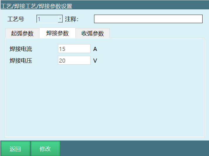
Welding Current: Current applied during welding. During welding, current flowing through welding circuit is the result of balance between wire feed speed and melting speed.
Welding Voltage: Welding voltage is arc voltage, providing welding energy and welding quality.
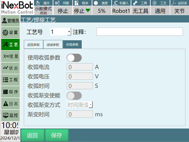
Use Arc End Parameters: After turning on switch, arc end parameters take effect.
Arc End Current: Current given by arc extinguisher when arc extinction is needed during welding.
Arc End Voltage: Refers to the maximum industrial frequency voltage allowed on the lightning arrester under the condition that the lightning arrester can extinguish the arc at the first zero crossing of industrial frequency follow current. Arc extinction voltage should be greater than the maximum industrial frequency voltage that may appear on the lightning arrester working bus, otherwise the lightning arrester may explode due to inability to extinguish the arc.
Arc End Time: Time that welding current/voltage maintains to arc end current/voltage.
For example: Arc end time is 1 second, indicating that after welding current/voltage reaches arc end current/voltage, will maintain for 1S then welding ends. According to different arc extinction media, arc extinction time is different, generally in seconds.
Arc End Gradient Enable: Controls the time from welding current/voltage gradient to arc end current/voltage. Note: After turning on gradient enable, the gradient parameters below will take effect.
Arc End Gradient Method: Time gradient.
Gradient Time: After turning on arc end gradient enable, set gradient time to 2 seconds. Time from arc end start to arc end end requires two seconds.
Arc end gradient time is 2 seconds, arc end current 35A, arc end voltage 10V. Within 2 seconds, arc end current and voltage will gradually become 35A, 10V, not directly changing from welding current/voltage to arc end current/voltage values.
3.5 Welding Equipment Settings
Setting welding equipment needs to be modified in "Craft/Welding Process/Welding Equipment Settings". Related steps as follows:
Enter "Craft/Welding Process/Welding Equipment Settings" page.
Click "Modify", the modify button changes to save. Click the selection box below to select the needed function.
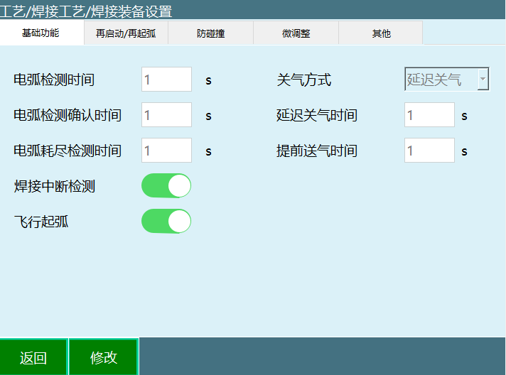
4 Basic Functions
Arc Detection Time: Time from controller sending arc start signal to system receiving arc start success signal from welding machine! If system does not receive arc start success within this time, system will report arc start failure error.
Arc Detection Confirmation Time: To prevent interference signals from dust and other obstacles, delay a period of time to ensure arc has signal transmission. During this time, if arc start success signal is continuously detected, welding begins.
(Note: Arc detection time should be greater than arc detection confirmation time.)
Arc Exhaustion Detection Time: During welding process, time that welding can continue after arc start signal is interrupted. If arc start signal is not received after exceeding set time, will report error.
Delayed Gas Off Time: After welding ends and arc extinction signal is sent, welding wire has not cooled yet. If protective gas stops at this time, oxidation will still occur. Therefore gas needs delayed shutdown, and also has the function of cooling welding torch.
- Set delayed gas off 1s. After welding completes, in [Monitor] - [IO Status - Digital Output] interface, can see the set gas supply signal port will delay 1S before closing.
Early Gas Off Time: Time parameter for ending gas supply before arc end.
- Set early gas off 1s. After welding completes, in [Monitor] - [IO Status - Digital Output] interface, can see the set gas supply signal port will close 1S early.
Flying Arc Start: During movement from safety point to welding start point, gas supply already starts early.
Early Gas Supply Time: During welding, to prevent welding wire from being oxidized by air, may need to supply gas early to blow away air around welding torch, reducing porosity in welding seam and making welding seam appear smoother.
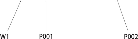
As shown above, W1 represents safety point, P001 represents welding start point, P002 represents welding end point, P001-P002 represents welding distance.
4.1 Turn On Flying Arc Start
- When set gas supply time is less than time from safety point to welding start point.
For example: Set early gas supply time 4s. Robot needs 10s from W1 to welding start point P001.
Execution effect: W1 to P001 needs 10s. At 6th second, robot starts gas supply. At 10s, reaches P001 point and starts arc.
- When set gas supply time is greater than time from safety point to welding start point.
For example: Set early gas supply time 4s. Robot needs 2s from W1 to welding start point P001.
Execution effect: W1 to P001 needs 2s. After reaching P001, robot will stay at P001 for 2s. At 4s, arc will start.
4.2 Turn Off Flying Arc Start
Without flying arc start: After moving from safety point to welding start point, start early gas supply.
For example: Turn off flying arc start, early gas supply time 4S.
Execution effect: Robot moves from W1 point (safety point) to welding start point P001, then starts gas supply. At 4s, robot starts arc.
4.3 Restart/Re-Arc
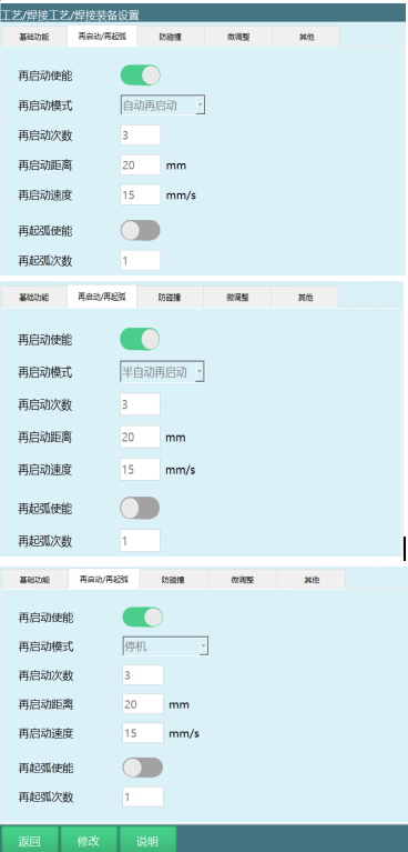
Restart Enable: Restart enable. When arc break occurs and arc start signal is given, is effective.
Auto Restart: After detecting arc break, servo and program are both in running state. Within set arc detection time, give arc start signal again, program continues running.
Semi-Auto Restart: After detecting arc break, servo is in running state, program is in paused state. At this time, need to manually click start button. Within set arc detection time, give arc start signal again, program continues running.
Stop: After detecting arc break, servo is in ready state, program is in stopped state. After arc break, need to clear error, then manually click start button.
Restart Distance: Distance for restart action to retreat. When breakpoint runs again during welding process, can retreat a certain distance (to prevent empty welding).
Restart Speed: Speed for restart action to retreat. When speed is 0, will not retreat.
Re-Arc Enable: First send signal to let welding machine start arc. If arc start fails, execute arc start action again in place. If arc start succeeds, execute welding normally. If still no success within set number of times, stop and report error.
Re-Arc Count: Maximum number of times to execute re-arc in the interval between current welding machine start and welding end. Exceeding will no longer execute restart.
- Set re-arc count to 2 times. After arc break occurs, if arc start signal is given more than 2 times without success, will report error.
| Restart Function (Note: Using this function requires turning on welding interruption detection in basic functions) |
|---|
| Welding trajectory straight line P001-P002 |
| Welding start point P001, welding end point P002 |
| Auto Restart | Execution Effect |
|---|---|
| Restart Distance 20mm | After welding starts, robot moves from P001 to P002. After arc break occurs, controller warns (Welding arc break detected). At this time, servo and program are both in running state. |
| Restart Speed 15mm/s | During movement from P001 to P002, arc break occurs. Robot will move 20mm at 15mm/s speed at the arc break point according to set restart distance and restart speed parameters. After reaching retreat distance, give arc start signal again, robot executes welding operation again. |
| Semi-Auto Restart | Execution Effect |
|---|---|
| Restart Distance 20mm | After welding starts, robot moves from P001 to P002. After arc break occurs, controller warns (Welding arc break detected). At this time, servo is in running state, program is in paused state. A popup prompt about arc break will appear. |
| Restart Speed 15mm/s | During movement from P001 to P002, arc break occurs. Click the popup prompt's confirm button, then click start button. Robot will move 20mm at 15mm/s speed at the arc break point according to set restart distance and restart speed parameters. After reaching retreat distance, give arc start signal again, robot executes welding operation again. |
| Stop | Execution Effect |
|---|---|
| Restart Distance 20mm | After welding starts, robot moves from P001 to P002. After arc break occurs, controller reports error (Welding arc break detected). At this time, servo is in ready state, program is in stopped state. A popup prompt about arc break will appear. |
| Restart Speed 15mm/s | During movement from P001 to P002, arc break occurs. After error, first click clear error button, then click popup prompt's confirm button, then click start button. Another popup prompt will appear (Breakpoint execution, First line run). |
| 1. Select breakpoint execution effect: Robot will move 20mm at 15mm/s speed at the arc break point according to set restart distance and restart speed parameters. After reaching retreat distance, give arc start signal again, robot executes welding operation again. | |
| 2. Select run from first line effect: Robot will execute welding operation from the beginning. |
| Restart Count | Number of arc start signals that can be given when arc break occurs |
|---|---|
| Execution effect: Set restart count to 3. After arc break, arc start signal can be given at most 3 times. When giving arc start signal the 4th time, controller will report error (Welding arc break detected). |
4.4 Anti-Collision
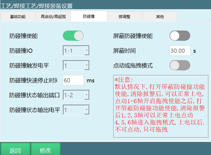
Anti-Collision Enable: Turn on enable to detect anti-collision signal.
Anti-Collision IO: IO input signal when collision occurs.
Anti-Collision Trigger Level: 1-High level, 0-Low level.
Anti-Collision Quick Stop Time: Time from triggering anti-collision to robot stopping.
- Set anti-collision quick stop time to 60ms. After collision occurs, time from robot working to stopping is 60ms.
Anti-Collision Status Output Port: When anti-collision is triggered, specified IO output port outputs signal.
Select anti-collision status output level 1. Set IO output port is 1-2. When collision occurs, output port 1-2 will change from low level 0 to high level 1.
Select anti-collision status output level 0. Set IO output port is 1-2. When collision occurs, output port 1-2 will change from high level 1 to low level 0.
Anti-Collision Status Output Level: 1-High level, 0-Low level.
Mask Anti-Collision Enable:
After welding torch collision, controller reports error (Welding torch anti-collision triggered).
At this time, cannot clear error. Need to turn on mask anti-collision enable, set mask time. During mask time, anti-collision signal is not detected.
If anti-collision signal is released, mask anti-collision enable immediately closes.
Mask Time: Mask time parameter when collision occurs.
Turn on mask anti-collision enable, set mask time 10s. When collision occurs, will mask for 10s, convenient to move welding torch to safe position.
After reaching mask time, controller reports error (Mask ended, welding torch anti-collision triggered).
Jog or Drag Mode:
After collision occurs, turn on mask anti-collision enable, set mask time.
Turn on jog or drag mode enable. After collision, can drag axes 4, 5, 6 (at this time, axes 4, 5, 6 can only be dragged, axes 1, 2, 3 can be jogged).
4.5 Fine Adjustment
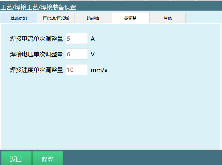
Welding Current Single Adjustment Amount: Single adjustment amplitude of welding current during welding process.
For example: Welding current single adjustment amount is 5A. During welding, if want to increase or decrease current value, can click Craft Bar - [Welding Process] - [Fine Adjustment].
Click given value increase will increase current value by 5A during welding. Click given value decrease will decrease current value by 5A during welding.
(Note: The increased or decreased value is adjusted according to the set welding current single adjustment amount.)
Welding Voltage Single Adjustment Amount: Single adjustment amplitude of welding voltage during welding process.
For example: Welding voltage single adjustment amount is 6V. During welding, if want to increase or decrease voltage value, can click Craft Bar - [Welding Process] - [Fine Adjustment].
Click given value increase will increase voltage value by 6V during welding. Click given value decrease will decrease voltage value by 6V during welding.
(Note: The increased or decreased value is adjusted according to the set welding voltage single adjustment amount.)
Welding speed single adjustment: Welding equipment parameters can set fine adjustment single increase/decrease amplitude.
4.6 Other
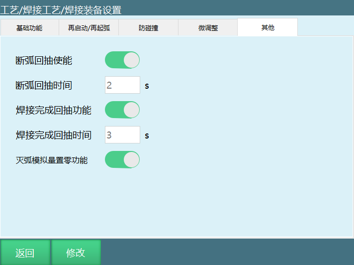
Welding Completion Retraction Function: At the end of welding, welding torch will receive wire retract signal. Welding wire will retract to prevent collision with workpiece when moving to next welding point.
Welding Completion Retraction Time: Time for retracting welding wire after completing welding.
- Turn on welding completion retraction enable, set completion retraction time 3 seconds. After welding ends, time from receiving wire retract signal to wire retract end totals 3 seconds.
Arc Break Retraction Enable: When welding current exceeds welding machine's rated load rate, welding machine has brief protection, arc break occurs. Welding wire needs retraction to prevent adhesion with workpiece.
Arc Break Retraction Time: Time for retracting welding wire after welding arc break.
- Turn on arc break retraction enable, set arc break retraction time 2 seconds. To prevent welding wire adhesion with workpiece, welding wire retraction time needs 2 seconds.
Arc Extinction Analog Zero Function: After welding ends, analog voltage and current signals return to zero (analog output).
5 Weaving Parameters
Setting weaving parameters needs to be modified in "Craft/Welding Process/Weaving Parameters". Related steps as follows:
Enter "Craft/Welding Process/Weaving Parameters" page. Weaving file has 9 craft numbers to choose from. Select the weaving parameters to modify, click the modify button at the bottom. All input boxes become input-enabled.
After inputting, click save button to complete save.
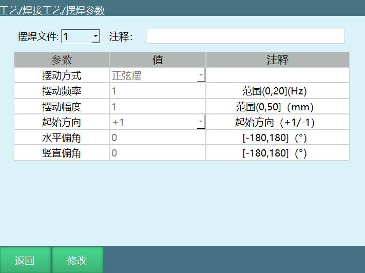
INEXBOT weaving supports four weaving methods: Sine weave, Zigzag weave, Circular weave, External axis fixed-point weave.
Various parameters such as weaving frequency, weaving amplitude, starting direction, horizontal angle, vertical angle, etc. can be adjusted according to actual industrial site requirements.
Weaving Amplitude: Larger amplitude means larger robot weaving.
Weaving Frequency: Higher frequency means faster robot weaving frequency.
Starting Direction: +1, start from a certain point and go upward first; -1, start from a certain point and go downward first.
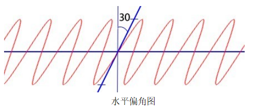
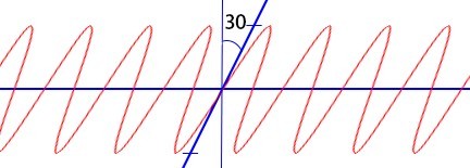
Horizontal Angle: Set weaving trajectory with 30° horizontal angle.
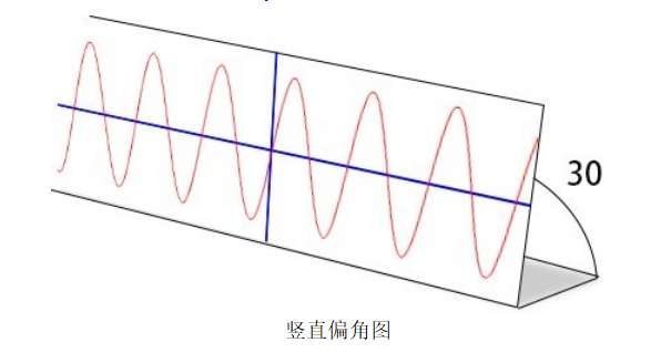
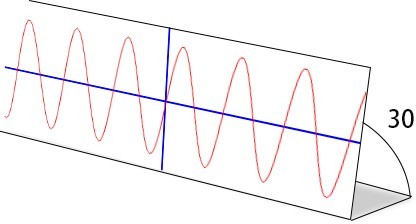
Vertical Angle: Set weaving trajectory with 30° vertical angle.
Move: Robot moves forward the set time for each weave, then enters the next weave.
Stay: Robot stays the set time for each weave.
Starting Direction: +1, start from a certain point and go upward first; -1, start from a certain point and go downward first.
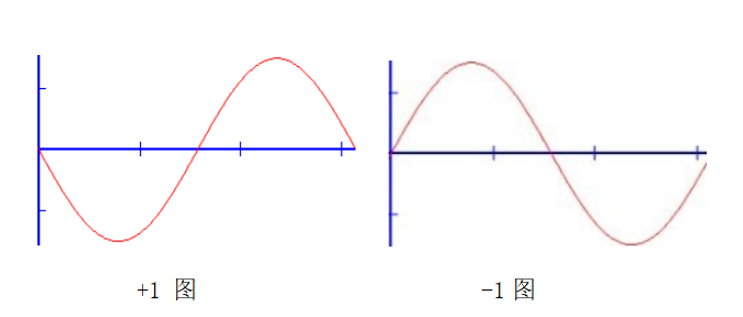
Left Stay Time/Right Stay Time: When weaving method selects Zigzag weave or fixed-point weave, will have left stay time/right stay time. During Zigzag weave/fixed-point weave, time to stay when reaching a target point.
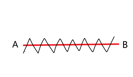
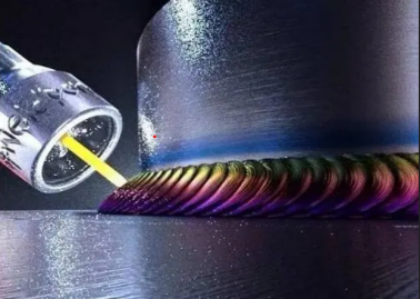
Weaving is welding operation where weld seam heat source performs regular lateral oscillation on the workpiece during welding. Weaving effect as shown.
6 Intersection Line Settings
Intersection line settings need to be modified in "Craft/Welding Process/Intersection Line Settings".
Related steps as follows:
- Enter "Craft/Welding Process/Intersection Line Settings" page, as shown:
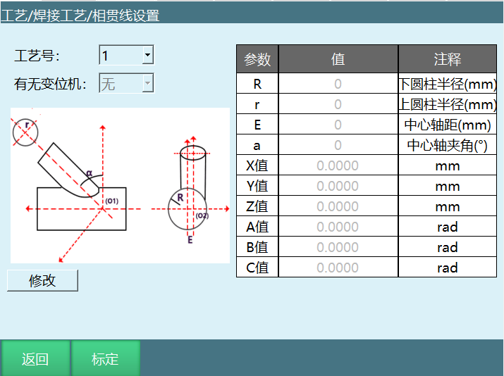
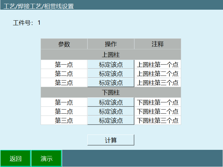
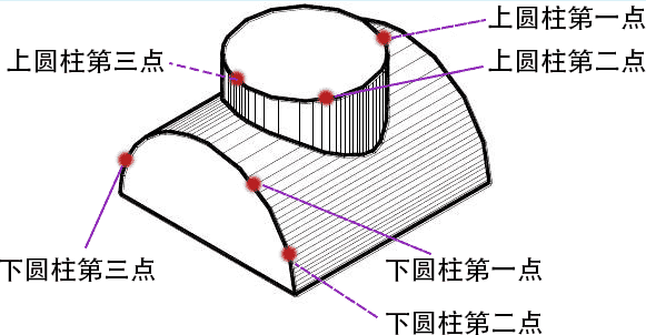
- Calibration before use can reduce errors. Click calibration to enter calibration interface. If don't know how to calibrate, there is a demo button in the interface to view, as shown:
7 Manual Operation
Setting manual operation needs to be modified in "Craft/Welding Process/Manual Operation". Related steps as follows:
Enter "Craft/Welding Process/Manual Operation" page.
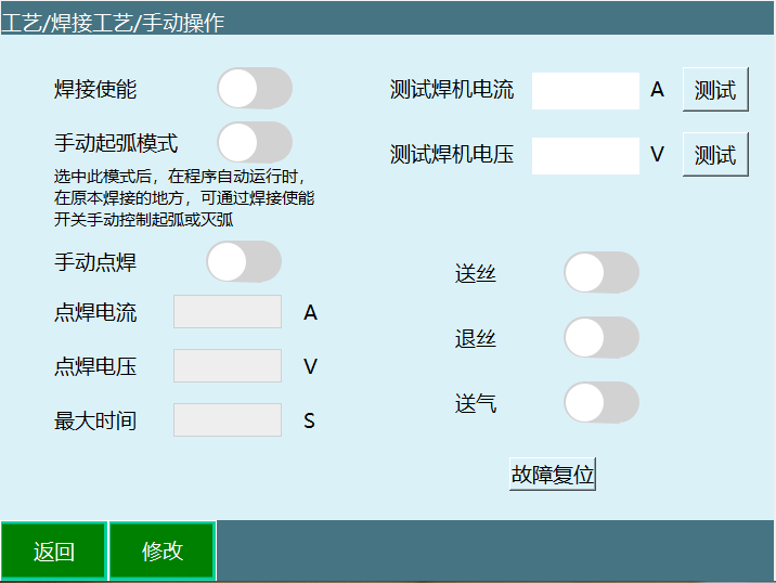
Welding Enable: After turning on welding enable, robot will execute welding operation, otherwise only moving trajectory.
After welding trajectory program is written, can first confirm trajectory is correct in teach mode.
Switch to run mode and turn on welding enable, robot will execute welding function. When program is in run mode, press "stop", then press "start". After program restarts, will no longer execute welding function.
Manual Arc Start Mode: Select this mode. During program automatic running, can manually control arc start or arc extinction through welding enable switch.
Robot moves from welding start point P001 to welding end point P004. Turn on welding enable, robot will start arc. Turn off welding enable, robot will extinguish arc.
In run mode, during robot motion, turn on welding enable at P002, turn off welding enable at P003. Then during movement from P002 to P003, robot maintains arc state. During movement from P003 to P004, robot maintains arc extinction state.
Robot moves from W1 (safety point) to welding start point P001. Turn on welding enable, robot will not start arc. After reaching P001, robot will start arc.
Without manual arc start mode: Robot moves from welding start point P001 to welding end point P004. Welding enable key is invalid (even if welding enable key is turned on, robot will not start arc).
Manual Spot Weld: Set spot welding current, spot welding voltage, maximum time, click save.
Long press manual spot weld button (hold to be effective, release is invalid). Robot performs welding. Release button, robot stops welding.
Spot Welding Current: Spot welding output current.
Spot Welding Voltage: Spot welding output voltage.
Maximum Time: Maximum time that manual spot weld button is allowed to be held.
Note: Maximum time set to 5s. Hold manual spot weld, robot welds 5s. Exceeding 5s, even if holding manual spot weld button, robot will not perform welding.
Fault Reset: Effective when using digital welding machine. Can be used to reset welding machine fault.
Wire Feed: Wire feed is needed when welding starts.
Wire Retract: Wire retract operation after welding ends.
Gas Supply: Turn on gas supply.
For welding convenience, [Craft]/[Welding] has been added to the status bar.
Note: Need to select [Welding Process] in Settings/Operation Parameters - Craft Selection, modify and save. Status bar displays [Welding]. Click on the welding, will pop up manual operation welding window.
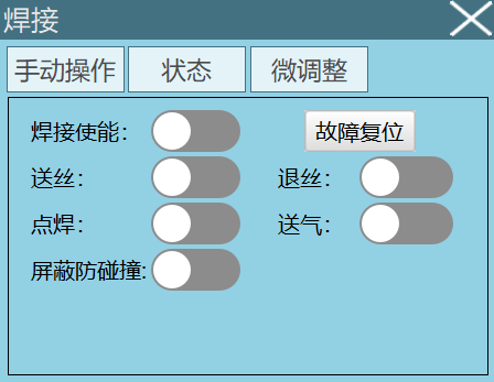
[Manual Operation] has the same effect as "Craft/Welding Process/Manual Operation" page's manual operation. This status bar can more conveniently see signals during welding process, changes in current and voltage values, etc.
Mask Anti-Collision: After anti-collision is triggered, turn on mask anti-collision switch. According to welding equipment settings - anti-collision parameters. After turning on, release collision during mask time, convenient to move welding torch to safe position.
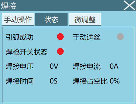
[Status]
Arc Success/Manual Wire Feed/Welding Torch Switch Status: Green is on, red is off.
Welding Current/Voltage: Input current and voltage.
Welding Time: Welding time from welding start to before welding end. Records welding time after startup.
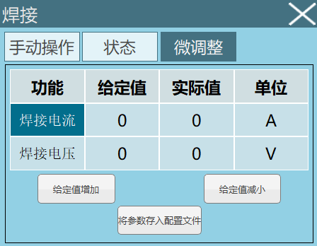
[Fine Adjustment]
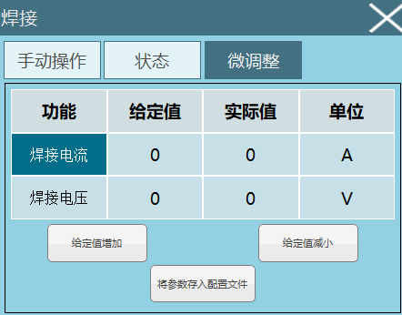
Store Parameters to Config File: Save parameters during welding. Click save button, parameters automatically overwrite into instructions or parameters.
When instruction uses custom parameters, saves to instruction.
When using welding craft number parameters, saves to welding parameters.
Given Value Increase/Given Value Decrease: Select the parameter to adjust. Click given value increase, given value decrease to adjust. Takes effect immediately.
For example: In welding process - welding equipment settings - fine adjustment interface, set welding current single adjustment amount to 5A. During welding, if want to increase or decrease current value, can click [Given Value Increase], [Given Value Decrease].
Click given value increase will increase current value by 5A during welding. Click given value decrease will decrease current value by 5A during welding.
(Note: The increased or decreased value is adjusted according to the set welding current single adjustment amount.)
For example: In welding process - welding equipment settings - fine adjustment interface, welding voltage single adjustment amount is 6V. During welding, if want to increase or decrease voltage value, can click [Given Value Increase], [Given Value Decrease].
Click given value increase will increase voltage value by 6V during welding. Click given value decrease will decrease voltage value by 6V during welding.
(Note: The increased or decreased value is adjusted according to the set welding voltage single adjustment amount.)
8 Welding Instruction Description
8.1 ARCON Instruction - Welding Start
This instruction can execute arc start operation. After selecting file label, parameters default to run according to parameters set and saved in welding process interface. Turn on use temporary craft parameter switch, parameters in instruction take precedence.
ARCON: Welding parameter craft number to use.
8.2 ARCOFF Instruction - Welding End
This instruction can execute arc extinction operation. After selecting file label, parameters default to run according to parameters set and saved in welding process interface. Turn on use temporary craft parameter switch, parameters in instruction take precedence.
ARCOFF: Execute arc extinction operation. Select the craft number corresponding to welding start.
8.3 ARCSET Instruction - Welding Settings
This instruction can set welding current and voltage.
8.4 WVON Instruction - Weaving Start
When this instruction executes, weaving starts. Before executing this instruction, please run welding start ARCON instruction first.
WVON: Weaving parameter craft number.
8.5 WVOFF Instruction - Weaving End
When this instruction executes, weaving ends.
8.6 CIL Instruction - Intersection Line
Intersection line instruction method is similar to MOVC.
Example: MOVJ P0001
CIL P0002
CIL P0003
Point: Select local position variable/global position variable/bound variable. When value is "New", inserting this instruction creates a new P variable and records robot's current position to the P variable.
V: Speed, unit mm/s.
PL: Smoothing level.
ACC: Acceleration, unit percentage.
DEC: Deceleration, unit percentage.
TIME: Early execution time, unit ms.
ID: Intersection line craft number.
8.7 FSWELDON Instruction - Fish Scale Weld Start
Execute this instruction to start fish scale weld trajectory. Before executing this instruction, please run welding start ARCON instruction first.
Fish scale weld parameters are filled directly in instruction.
T: Spot weld time, unit s.
L1: Welding distance, unit mm.
L2: Empty run distance, unit mm.
2024/12/27 Note: Due to version change issues, some versions have not been updated in time. The instruction here may still be TIGWELDON. Special note.
8.8 FSWELDOFF Instruction - Fish Scale Weld End
Execute this instruction to end fish scale weld trajectory.
2024/12/27 Note: Due to version change issues, some versions have not been updated in time. The instruction here may still be TIGWELDOFF. Special note.
8.9 FEEDWIRE Instruction - Wire Feed
Execute this instruction to turn on wire feed signal within parameter time.
T: Wire feed time, unit s.
8.10 ARCBUILTIN Instruction - Welding Machine Built-in Process
This instruction can currently be used with Aotai welding machine.
Built-in Process Number: Welding machine built-in process number.
Parameter A: Called by $builtin_a.
Parameter B: Called by $builtin_b.
Parameter C: Called by $builtin_c.
Parameter D: Called by $builtin_d.
Parameter E: Called by $builtin_e.
8.11 WELDPATHSTART Instruction - Initial Weld Pass Recording Start
WELDPATHSTART: Wrap initial weld pass together with end. Only supports linear, arc, full circle in between. Initial weld pass recording end.
8.12 WELDPATHOFFSET Instruction - Weld Pass Offset Calculation
Original weld pass: Calculate offset weld pass. Execute in calculated order during running. Weld pass 0 saves initial weld pass.
X axis offset, Y axis offset, Z axis offset, A axis offset, B axis offset, C axis offset: Offset amounts for X, Y, Z, A, B, C axes.
Calculation result stored in: WELDPATH1~21 saves weld pass offset result. Weld pass 0 saves initial weld pass. Other interfaces cannot be modified. Without recording and calculating offset, running weld pass offset is invalid.
8.13 STARTOFFSETWELD Instruction - Run Offset Weld Pass
Move trajectory in weld pass. Speed and other parameters same as initial weld pass. Used together with weld pass offset calculation. Each weld pass has same length, welding at different angles and positions.
8.14 REFP Instruction - Weaving Reference Point
Reference point: Reference point 1-2.
Note: Red trajectory indicates weaving trajectory through determining weaving direction.
Only select reference point 1/reference point 2.
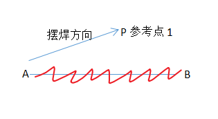
Select both reference point 1 and reference point 2:
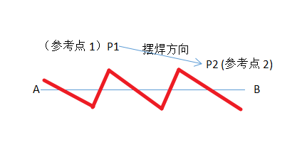
Auto Correct Speed: Whether to turn on auto correction. After turning on, will offset weld pass start point to between two reference points.
Green trajectory indicates weaving trajectory and direction after correcting weaving start point.
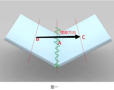
For example: As shown, B is reference point 1, C is reference point 2. After turning on auto correct enable, weld pass start point is the center point of distance between two reference points.
Reference point variable name: New.
8.15 WELDPATHCOUNT Instruction - Weld Pass Count Calculation
Calculation result stored in variable type: INT/GINT for calculating number and sequence of weld passes to run.
Select use weld pass: 1-21.
8.16 SPOTWELD Instruction - Spot Weld
When this instruction executes, robot starts executing spot welding operation.
Welding Parameter Label: Welding parameter craft number used during spot welding.
Welding Time: Spot welding time.
Spot welding usage method:
Set welding signal, current-voltage matching parameters, welding equipment parameters.
In welding process - manual operation interface, set spot welding current, voltage, time parameters.
After setting needed parameters, in manual operation interface or welding process status interface, click spot welding enable button. Will find that the set arc start and gas supply signal ports will open (because welding machine is not connected, wire feed and wire retract signal ports have no response).
9 Usage Cases
9.1 Normal Arc Start Welding
9.1.1 Parameter Settings
Enter "Craft/Welding Machine Settings", set welding machine control method - Analog welding machine.
Enter "Craft/Welding IO". Digital input: Arc start success signal 1-1. Digital output: Arc start signal 1-2. Analog input welding current signal DIN1-1, welding voltage signal DIN1-2. Analog output given current signal DOUT1-1, given voltage signal DOUT1-2.
Enter "Craft/Current-Voltage Matching". Set current row 1 welding current fill [1], actual welding current [10]. Set voltage row 1 welding voltage fill [1], actual welding voltage fill [10].
Enter "Craft/Welding Process/Welding Parameter Settings". Set arc start parameters: Arc start current [8]A, arc start voltage [8]V, arc start time [2]S. Welding parameters: Welding current [10]A, welding voltage [10]V. Arc end current [7]A, arc end voltage [7]V, arc end time [2]S.
Enter "Craft/Welding Equipment Settings" - Basic functions: Arc detection time [2]S, arc detection confirmation time [1]S, arc exhaustion detection time [1]S, flying arc start on. Gas off method select delayed gas off [2]S.
Enter "Craft/Manual Operation", turn on welding enable switch, turn on manual arc start mode, set manual spot welding current 8A, spot welding voltage 8V, maximum time 2S.
Note: All parameter values are for example illustration only.
9.1.2 Program Writing
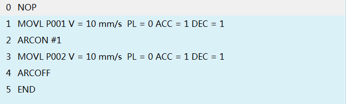
9.1.3 Instruction Meaning
Robot moves to welding start point P001.
ARCON#1 (includes 4s early gas supply time and 1s arc detection time) starts arc. Execute welding parameter label 1.
0~4s, 4s early gas supply time (At 0s, start gas supply. Detect gas present, gas detection signal outputs high level, i.e., DOUT port 1-4 lights up. After 4s, provide arc start signal, i.e., at 4s DOUT port 1-1 lights up). 4~5s, 1s arc detection time (If arc start success signal is detected as high level within 1s, i.e., DIN port 1-1 lights up, program continues running. If not detected, will report "Waiting for welding arc start success signal timeout" error).
- Robot moves to welding end point P002.
During this process, robot starts welding function. Arc start voltage 100V, arc start current 10A, arc start time 10s, welding voltage 200V, welding current 20A, arc extinction voltage 300V, arc extinction current 30A, arc extinction time 30s.
(All values correspond to actual voltage and actual current in "Current-Voltage Matching", not set voltage and set current.)
- ARCOFF (includes 3s arc exhaustion detection time and 5s delayed gas off time).
0~3s, 3s arc exhaustion detection time (At 0s, arc start signal outputs low level, i.e., DOUT port 1-1 lights off. If arc start success signal is detected as low level within 3s, i.e., DIN port 1-1 lights off, program continues running. If not detected, will report "Waiting for welding arc extinction success signal timeout" error).
3~8s, 5s delayed gas off time (At 8s, stop gas supply. Gas detection signal outputs low level, i.e., DOUT port 1-4 lights off).
9.1.4 Program Insertion Method
Click "Project", click "New", input program name, click "OK".
Move robot to welding start point. Click "Insert", select "Motion Control", select MOVL, click "OK", modify speed value, click "OK".
Click "Insert", select "Welding Control", select ARCON, click "OK", input file number (file number corresponds to value in welding parameter settings interface), click "OK".
Move robot to welding end point. Click "Insert", select "Motion Control", select MOVL, click "OK", modify speed value, click "OK".
Click "Insert", select "Welding Control", select ARCOFF, click "OK", click "OK".
Trajectory Confirmation: After program is written, rotate key to switch teach pendant from teach mode to run mode. Click "start", confirm robot's running trajectory is correct and meets requirements.
Welding: After confirming trajectory is correct, turn on welding enable, robot will execute welding function.
Welding enable turn on method: Switch teach pendant to teach mode, click "Welding" button in upper right corner.
Appears as shown:
Select "Welding Enable", turn on enable.

When program is in run mode, press "stop", then press "start". After program restarts, will no longer execute welding function.
9.2 Weaving Usage Case
9.2.1 Parameter Settings
Enter "Craft/Welding Process/Weaving Parameters", set parameters, as shown:
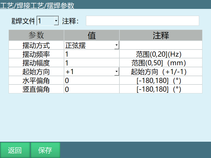
Note: Parameter values here are for example illustration only.
9.2.2 Program Writing
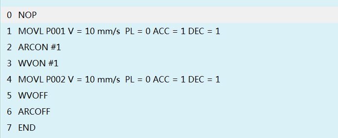
9.2.3 Operation Meaning
Steps 1~2, 3~4 and 6 meanings refer to arc start welding usage case.
- Line 3 WVON#1.
Weaving start, execute weaving file 1 parameters. (If WVON#2, weaving start, execute weaving file 2 parameters).
Weaving method: Sine weave.
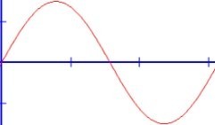
Starting direction +1, start from a certain point and go upward first.
Starting direction -1, start from a certain point and go downward first.

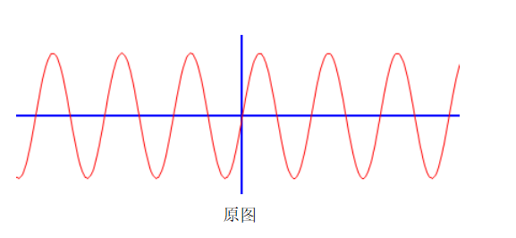
Original shape:

Horizontal angle: 30 degree angle.
Vertical angle: 30 degree angle.
- Line 5 WVOFF weaving end.
9.2.4 Operation Steps
Program Writing: Click "Project", click "New", input program name, click "OK".
Move robot to welding start point. Click "Insert", select "Motion Control", select MOVL, click "OK", modify speed value, click "OK".
Click "Insert", select "Welding Control", select ARCON, click "OK", input file number (file number corresponds to value in welding parameter settings interface), click "OK".
Click "Insert", select "Welding Control", select WVON, click "OK", input file number (file number corresponds to value in weaving parameters interface).
Move robot to welding end point, click "Insert", select "Motion Control", select MOVL, click "OK", modify speed value, click "OK".
Click "Insert", select "Welding Control", select WVOFF, click "OK", click "OK".
Click "Insert", select "Welding Control", select ARCOFF, click "OK", click "OK".
Trajectory Confirmation: After program is written, rotate key to switch teach pendant from teach mode to run mode. Click "start", confirm robot's running trajectory is correct.
Welding: After confirming trajectory is correct, turn on welding enable, robot will execute welding function. Welding enable turn on method is introduced in arc start welding case.
9.2.5 Fixed-Point Weaving Trajectory
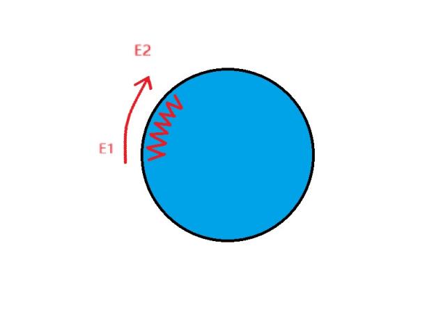
Calibrate two points on external axis E1 (external axis rotation axis start point), E2 (external axis rotation axis end point). E1-E2 determines external axis rotation direction and actual welding trajectory.
Red line segment on circle indicates weaving trajectory on external axis.
External axis rotates while robot performs fixed-point weaving. Weaving trajectory is the part indicated by red curve in the figure below.
If E1-E2 robot displacement direction is same as external axis direction, trajectory is as shown. If robot displacement direction is perpendicular to external axis direction, weaving direction will rotate 90°.
9.2.6 Fixed-Point Weaving Instruction Writing
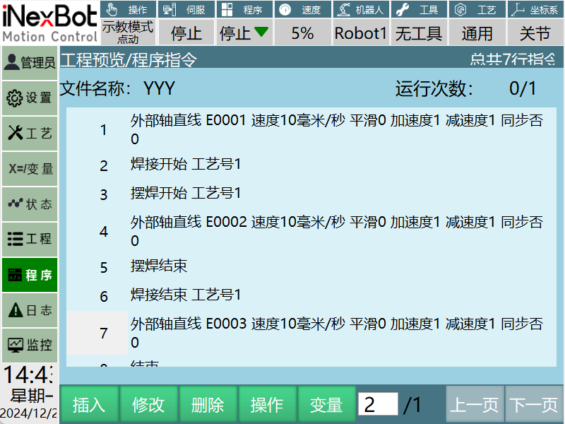
9.3 Fish Scale Weld Usage Case
9.3.1 Program Writing
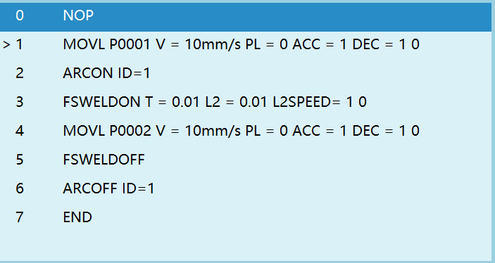
All parameter values are for example illustration only.
9.3.2 Operation Meaning
Note: Steps 1~2, 3~4 and 6 meanings refer to welding usage case.
Line 3 FSWELDON fish scale weld start.
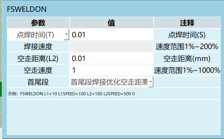
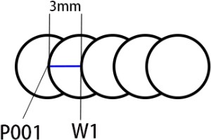
Robot starts arc. Robot welds at P001 point for 2s (i.e., T=2s). Then robot extinguishes arc. Empty run 3mm (i.e., L2=3mm) distance to W1 point.
Robot starts arc at W1 point. Welds at W1 point for 2s. Extinguishes arc. Empty run 3mm to W2 point.
①Start arc, ②Weld 2s, ③Extinguish arc, ④Empty run 3mm. Loop the previous 4 steps until reaching welding end point (P002).
Line 5 FSWELDOFF fish scale weld end.
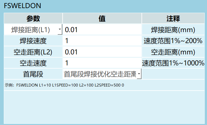
Line 3 FSWELDON fish scale weld start.
Robot starts arc. Robot starts from P001 point, runs L1 distance to W1 point in welding state (distance between P001 and W1 is 3MM, i.e., welding distance). Then robot extinguishes arc, empty runs 3mm (i.e., L2=3mm) to W2 point. Robot starts arc at W2 point, runs from W2 while welding to W3 point. Then robot extinguishes arc, empty runs 3mm to W4 point. ①Start arc, ②Weld 3MM, ③Extinguish arc, ④Empty run 3mm. Loop the previous 4 steps until reaching welding end point (P002).
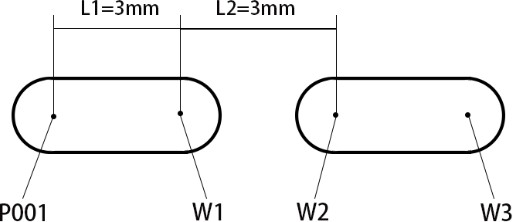
Line 5 FSWELDOFF fish scale weld end.
9.3.3 Operation Steps
Click "Project", click "New", input program name, click "OK".
Move robot to welding start point.
Click "Insert", select "Motion Control", select MOVL, click "OK", modify speed value, click "OK".
Click "Insert", select "Welding Control", select ARCON, click "OK", input file number (file number corresponds to value in welding parameter settings interface), click "OK".
Click "Insert", select "Welding Control", select FSWELDON, click "OK", select fish scale weld type: Selection 1: Row 1 parameter select T. Selection 2: Row 1 parameter select L1, input corresponding values.
Move robot to welding end point, click "Insert", select "Motion Control", select MOVL, click "OK", modify speed value, click "OK".
Click "Insert", select "Welding Control", select FSWELDOFF, click "OK", click "OK". Click "Insert", select "Welding Control", select ARCOFF, click "OK", click "OK".
Trajectory Confirmation: After program is written, rotate key to switch teach pendant from teach mode to run mode. Click "start", confirm robot's running trajectory is correct.
Welding: After confirming trajectory is correct, turn on welding enable, robot will execute welding function. Enable turn on method is introduced in arc start welding case.
9.4 Multi-Layer Multi-Pass Welding Usage Case
9.4.1 Parameter Settings
Enter "Craft/Welding Machine Settings", set welding machine control method - Analog welding machine.
Enter "Craft/Welding IO". Digital input: Arc start success signal 1-1. Digital output: Arc start signal 1-2. Analog input DIN1-1. Analog output DOUT1-1.
Enter "Craft/Current-Voltage Matching". Set current row 1 welding current fill [1], actual welding current [10]. Set voltage row 1 welding voltage fill [1], actual welding voltage fill [10].
Enter "Craft/Welding Parameter Settings". Set arc start parameters: Arc start current [8]A, arc start voltage [8]V, arc start time [2]S. Welding parameters: Welding current [10]A, welding voltage [10]V. Arc end current [7]A, arc end voltage [7]V, arc end time [2]S.
Enter "Craft/Welding Equipment Settings" - Basic functions: Arc detection time [2]S, arc detection confirmation time [1]S, arc exhaustion detection time [1]S, flying arc start switch on. Gas off method - delayed gas off fill [2]S.
Enter "Craft/Manual Operation", turn on welding enable switch, turn on manual arc start mode switch, set manual spot welding current 8A, spot welding voltage 8V, maximum time 2S.
9.4.2 Operation Steps
Click "Project", click "New", input program name, click "OK".
Move robot to welding start point. Click "Insert", select "Motion Control", select MOVL, click "OK", modify speed value, click "OK".
Click "Insert", select "Welding Control", select ARCON, click "OK", input file number (file number corresponds to value in welding parameter settings interface), click "OK".
Click "Insert", select "Welding Control", select WVON, click "OK", input file number (file number corresponds to value in weaving parameters interface).
Move robot to welding end point, click "Insert", select "Motion Control", select MOVL, click "OK", modify speed value, click "OK".
Click "Insert", select "Welding Control", select WVOFF, click "OK", click "OK".
Click "Insert", select "Welding Control", select ARCOFF, click "OK", click "OK".
Trajectory Confirmation: After program is written, rotate key to switch teach pendant from teach mode to run mode. Click "start", confirm robot's running trajectory is correct.
Welding: After confirming trajectory is correct, turn on welding enable, robot will execute welding function (welding enable turn on method is introduced in arc start welding case).
9.4.3 Usage Example (2-Layer 3-Pass Weld)
Point-to-point.
Welding start.
Initial weld pass recording start.
Linear.
Initial weld pass recording end.
Welding end.
Weld pass offset calculation (2-layer 1-pass).
Weld pass offset calculation (2-layer 2-pass).
Weld pass count calculation (select weld passes to run and total weld passes to run).
Loop start (use weld pass total for judgment).
Return to safety point.
Welding start.
Run offset weld pass.
Welding end.
Loop end.
Note: 2-layer 3-pass weld: First layer is weld pass 1, second layer is passes 2 and 3.
3-layer 4-pass weld: First layer is weld pass 1, second layer is passes 2 and 3, third layer is passes 4, 5, 6, and so on.
9.5 Spot Welding Usage Case
9.5.1 Operation Steps
Enter "Craft/Welding Machine Settings", set welding machine control method - Analog welding machine.
Set welding signal.
| Input | Output |
|---|---|
| Digital Input | Arc start success signal 1-1 |
| Digital Output | Arc start signal 1-1 |
| Wire feed signal 1-2 | |
| Wire retract signal 1-3 | |
| Gas supply signal 1-4 | |
| Analog Input | AIN1-1 |
| Analog Output | AOUT1-1 |
Enter "Craft/Current-Voltage Matching". Set current row 1 welding current fill [1], actual welding current [10]. Set voltage row 1 welding voltage fill [1], actual welding voltage fill [10].
Enter "Craft/Manual Operation", turn on welding enable switch, set manual spot welding current 8A, spot welding voltage 8V, maximum time 2S.
9.6 Weaving Reference Point Usage Case
9.6.1 Parameter Settings
Enter "Craft/Welding Machine Settings", set welding machine control method - Analog welding machine.
Enter "Craft/Welding IO". Digital input: Arc start success signal 1-1. Digital output: Arc start signal 1-2. Analog input DIN1-1. Analog output DOUT1-1.
Enter "Craft/Current-Voltage Matching". Set current row 1 welding current fill [1], actual welding current [10]. Set voltage row 1 welding voltage fill [1], actual welding voltage fill [10].
Enter "Craft/Welding Parameter Settings". Set arc start parameters: Arc start current [8]A, arc start voltage [8]V, arc start time [2]S. Welding parameters: Welding current [10]A, welding voltage [10]V. Arc end current [7]A, arc end voltage [7]V, arc end time [2]S.
Enter "Craft/Welding Equipment Settings" - Basic functions: Arc detection time [2]S, arc detection confirmation time [1]S, arc exhaustion detection time [1]S, flying arc start switch on. Gas off method - delayed gas off fill [2]S.
Enter "Craft/Manual Operation", turn on welding enable switch, turn on manual arc start mode switch, set manual spot welding current 8A, spot welding voltage 8V, maximum time 2S.
Set current position as weaving reference point. Add a REFP instruction. MOVL trajectory plus REFP calibrated point forms weaving plane, determines weaving direction.
Reference point method: Weaving plane.
Weaving plane: Used with weaving start instruction to determine weaving coordinate system.
Note: Can be used during linear weaving. After weaving start, insert reference point instruction before motion instruction to determine weaving plane.
Usage example:
Point-to-point p001.
Welding start.
Weaving start.
Linear p002.
Weaving reference point P004.
Linear p003.
Weaving end.
Welding end.
Return to safety point.
Q&A
Q1: What welding machine control methods does the 2207 welding process manual support?
A: Supports two methods: analog control and digital control. Digital control supports four communication methods: CAN, ModBus RTU, EtherCAT, ModBus TCP.
Q2: How to set welding parameters?
A: Enter "Craft/Welding Process/Welding Parameter Settings" page. After clicking modify, can set arc start parameters (arc start current, voltage, time), welding parameters (welding current, voltage), and arc end parameters (arc end current, voltage, time). Each craft number supports independent configuration.
Q3: What is the purpose of flying arc start?
A: Flying arc start allows early gas supply during robot movement from safety point to welding start point, reducing waiting time and improving welding efficiency.
Q4: What weaving methods does weaving support?
A: Supports four weaving methods: Sine weave, Zigzag weave, Circular weave, External axis fixed-point weave.
Q5: What restart modes are available after arc break?
A: Three modes: Auto restart (servo and program continue running), Semi-auto restart (servo runs but program pauses, manual start needed), Stop (servo ready program stops, need to clear error then manual start).
Q6: What is fish scale weld instruction?
A: FSWELDON starts fish scale weld, FSWELDOFF ends fish scale weld. Parameters include spot weld time T, welding distance L1, empty run distance L2.
Q7: How to achieve multi-layer multi-pass welding?
A: Through WELDPATHSTART to record initial weld pass, then WELDPATHOFFSET to calculate offset weld pass, finally STARTOFFSETWELD to run offset weld pass, combined with loop to achieve multi-layer multi-pass welding.
Q8: How to use anti-collision function?
A: In welding equipment settings, turn on anti-collision enable, set anti-collision IO, trigger level, quick stop time and other parameters. After triggering, can set mask time to move welding torch to safe position.
Q9: What are manual spot welding operation steps?
A: In manual operation interface, set spot welding current, spot welding voltage, maximum time and save. Long press manual spot weld button to perform spot welding, release to stop.
Q10: How to perform fine adjustment?
A: In welding process - welding equipment settings - fine adjustment interface, set welding current/voltage single adjustment amount. During welding, click given value increase/decrease to adjust immediately. Adjustment amount is based on set single adjustment amount.