Coordinate Systems
"\u2713" indicates support for this instruction.
| Instruction Type | Foreground | Global Background | Local Background |
|---|---|---|---|
| Switch Tool | \u2713 | \u2713 | \u2713 |
| Switch User Coordinate | \u2713 | \u2713 | \u2713 |
| User Coordinate Transform | \u2713 | ||
| Switch External Axis | \u2713 |
| Instruction Type | Instruction | Single Step | Reverse | Trial Run | Pre-Execute | Pre-Executed |
|---|---|---|---|---|---|---|
| Coordinate | Switch Tool | Supported | Jump to first line | Not supported | Not supported | Supported |
| Coordinate | Switch User Coordinate | Supported | Jump to first line | Not supported | Not supported | Supported |
| Coordinate | User Coordinate Transform | Supported | Jump to first line | Not supported | Not supported | Supported |
| Coordinate | Switch External Axis | Supported | Jump to first line | Not supported | Not supported | Supported |
Coordinate Switching
SWITCHTOOL - Switch Tool
Format: SWITCHTOOL Instruction Name[Tool Number to Switch].
Function: Switch the parameters of the corresponding tool number (tool parameters, load parameters).
Parameters:
| Variable Type |
|---|
| Manual input, variable form (INT, GINT) range [0,999]. Number 0 means no tool. |
Notes:
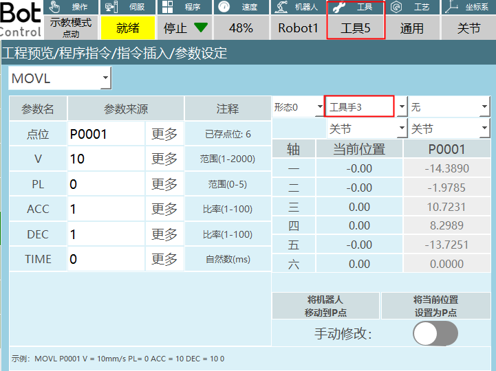
- After switching the tool, check if the robot point tool matches the actual tool used, otherwise it will cause program runtime errors.
As shown below: The set point tool number is 3, but the switch tool instruction selects number 5.
Example:
- NOP
- SET GI001 = 5
- SWITCHTOOL (GI001)
- END
Example description: When executing the instruction, the tool number in the teach pendant interface status bar will switch to tool number 5 set in the instruction.
SWITCHUSER - Switch User Coordinate
Format: SWITCHUSER Instruction Name[User Coordinate Number to Switch].
Function: Switch the parameters of the corresponding user number.
Parameters:
| Variable Type |
|---|
| Manual input, variable form (INT, GINT) range [1,999] |
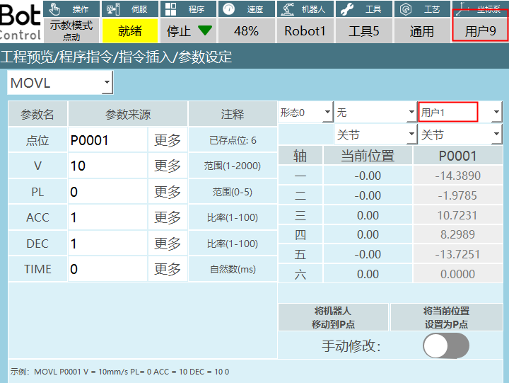
Notes: After switching the user coordinate, check if the robot point user matches the actual user, otherwise it will cause program runtime errors.
As shown below: The set point user number is 1, but the switch user instruction selects number 9.
Example:
- NOP
- SET I010 = 2
- SWITCHUSER (I010)
- END
Example description: When executing the instruction, the user number in the teach pendant interface status bar will switch to user number 2 set in the instruction.
USERCOORD_TRANS - User Coordinate Transform
Format: USERCOORD_TRANS [Instruction Name]1[User Coordinate A Number]2[User Coordinate B Number]3[User Coordinate C Number].
Function: User A and User B are combined to calculate User C.
For example: In a scenario where conveyor and camera are used together, the pallet is User A, the workpiece coordinate obtained by the camera relative to the pallet is User B, and finally the workpiece coordinate relative to the robot is User C.
Parameters:
| Parameter | Description |
|---|---|
| User Coordinate C | The user coordinate C calculated by combining User A and User B. The calculated parameters are stored in the selected user number. |
| User Coordinate A | The number to store User Coordinate A. |
| User Coordinate B | The number to store User Coordinate B. |
Example:
- NOP
- USERCOORD_TRANS (1)(2)(3)
- END
Example description: User Coordinate 1 and User Coordinate 2 calculate User Coordinate 3.
SWITCHSYNC - Switch External Axis
Format: SWITCHSYNC [Instruction Name]1,2,3[External Axis Group 1, External Axis Group 2, External Axis Group 3].
Function: Switch external axis type by setting the external axis group number.
Parameters:
| External Axis Group Number |
|---|
| The external axis group number to switch to, range [0,3]. For example: If external axis group 1 is set to single rotary axis, external axis group 2 is set to dual rotary axis. If the external axis group number in the switch external axis parameter setting interface is 2, running the instruction will switch the external axis to dual rotary axis. |
Example: In the robot configuration interface, external axis group 1 is set to single rotary axis, external axis group 2 is set to dual rotary axis, external axis group 3 is set to single linear axis.
- NOP
- TIMER T=1
- SWITCHSYNC 1
- MOVLEXT E0003 V = 50 mm/s PL = 0 ACC = 1 DEC = 1 SYNC = 1 0
- MOVLEXT E0004 V = 50 mm/s PL = 0 ACC = 1 DEC = 1 SYNC = 1 0
- END
Example description: When the program runs line 3, it switches to external axis group 1 (single rotary axis), then the robot runs a linear trajectory on the single rotary axis.
AI Retrieval Q&A (Q&A for Retrieval)
Q: How to use the SWITCHTOOL instruction to switch tools?
A: Use the SWITCHTOOL instruction, format: SWITCHTOOL Instruction Name[Tool Number to Switch]. For example, SWITCHTOOL (GI001) means switch to the tool number specified by GI001 variable.
Q: What should I pay attention to when switching tools?
A: After switching the tool, check if the robot point tool matches the actual tool used, otherwise it will cause program runtime errors. For example, if the set point tool number is 3 and the switch tool instruction selects number 5, it will cause program runtime errors.
Q: How to use the SWITCHUSER instruction to switch user coordinates?
A: Use the SWITCHUSER instruction, format: SWITCHUSER Instruction Name[User Coordinate Number to Switch]. For example, SWITCHUSER (I010) means switch to the user coordinate number specified by I010 variable.
Q: What should I pay attention to when switching user coordinates?
A: After switching the user coordinate, check if the robot point user matches the actual user, otherwise it will cause program runtime errors. For example, if the set point user number is 1 and the switch user instruction selects number 9, it will cause program runtime errors.
Q: How to use the USERCOORD_TRANS instruction for user coordinate transform?
A: Use the USERCOORD_TRANS instruction, format: USERCOORD_TRANS [Instruction Name]1[User Coordinate A Number]2[User Coordinate B Number]3[User Coordinate C Number]. For example, USERCOORD_TRANS (1)(2)(3) means User Coordinate 1 and User Coordinate 2 calculate User Coordinate 3.
Q: What is the application scenario of the USERCOORD_TRANS instruction?
A: The USERCOORD_TRANS instruction is used for User A and User B being combined to calculate User C. For example, in a scenario where conveyor and camera are used together, the pallet is User A, the workpiece coordinate obtained by the camera relative to the pallet is User B, and finally the workpiece coordinate relative to the robot is User C.
Q: How to use the SWITCHSYNC instruction to switch external axes?
A: Use the SWITCHSYNC instruction, format: SWITCHSYNC [Instruction Name]1,2,3[External Axis Group 1, External Axis Group 2, External Axis Group 3]. For example, SWITCHSYNC 1 means switch to external axis group 1.
Q: What is the parameter range of the SWITCHSYNC instruction?
A: The parameter range of the SWITCHSYNC instruction is [0,3], representing the external axis group number to switch to. For example, if external axis group 1 is set to single rotary axis and external axis group 2 is set to dual rotary axis, if the external axis group number in the switch external axis parameter setting interface is 2, running the instruction will switch the external axis to dual rotary axis.
Version History
| Version | Date | Changes | Author |
|---|---|---|---|
| 1.0.0 | 2026-04-08 | Initial version | tongmengyuan123 |