Human-Robot Collaboration Function
Document Overview
This document provides a detailed usage guide for the Human-Robot Collaboration (HRC) function, helping users correctly configure and use dynamics parameters, collision detection, torque feedforward, and hand-guiding functions. This manual applies to the HRC function configuration of INEXBOT robot controllers, including robot identification, mechanical function settings, and hand-guiding operations.
Terminology
| Term | Definition |
|---|---|
| Human-Robot Collaboration (HRC) | Work where humans and automated machines share workspace and perform tasks simultaneously |
| Dynamics Parameters | Parameters describing robot kinematics and dynamics characteristics |
| Collision Detection | Function for the robot to detect collisions and stop |
| Torque Feedforward | Control method that calculates torque in advance based on the dynamics model |
| Hand-Guiding | Method of teaching positions by manually dragging the robot |
HRC Overview
Human-Robot Collaboration (HRC) refers to work where humans and automated machines share workspace and perform tasks simultaneously. Due to the robot's complex nonlinearity, time-varying uncertainty, and strong coupling (especially during high-speed motion), to enable the robot to move at desired speeds and accelerations, each joint servo motor must have sufficient force and torque to drive the robot's links and joints. Otherwise, links will affect positioning and trajectory tracking accuracy due to sluggish motion. Therefore, feedforward torque control based on the dynamics model must be established to calculate feedforward compensation torque in real time.
Robot Identification
Pre-Identification Preparation
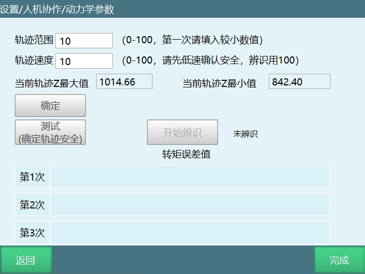
Before using mechanical functions, dynamics parameters must first be set up so that the controller can build the robot's dynamics model. To set dynamics parameters, navigate to "Settings/Human-Robot Collaboration/Dynamics Parameters". Before entering the identification interface, carefully read the identification-related precautions. When the robot performs trajectory tests, the range and speed should be set from small to large, gradually determining a maximum trajectory range that will not contact the surrounding environment. Then set the trajectory speed to 100 and begin identification. During identification, do not operate the teach pendant except when necessary, and personnel should stay away from the robot. If you need to stop identification, click the stop button on the teach pendant, press the emergency stop button, or switch modes.
Parameter Description
| Parameter | Description |
|---|---|
| Trajectory Range | Calculates the robot's maximum and minimum motion range based on the trajectory range |
| Trajectory Speed | Robot speed during operation, independent of global speed |
| Current Trajectory Z Max / Z Min | Indicates the range of the current trajectory Z |
| Identification Error | After identification, six parameters appear representing the error of each axis (smaller values indicate less error, cannot be 0) |
Identification Precautions
Important Notice
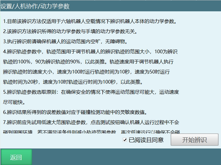
- Currently, this identification method only applies to six-axis robots with no load for identifying the robot body's dynamics parameters.
- The dynamics parameters obtained from this identification method are independent of manually filled dynamics parameters.
- Before executing identification, ensure the robot's motion range is clear and free of obstacles.
- In identification trajectory parameters, trajectory range adjusts the size of the robot's identification trajectory range. 100 means 100% of the identification trajectory, 90 means 90%, and so on. Trajectory speed adjusts the speed when the robot executes the identification trajectory.
- Identification trajectory parameter selection principle: maximize motion range and speed while ensuring safety.
- The error values from identification correspond to the sensitivity values in the collision detection function.
- Before identification, perform a trajectory test first. Start with low speed and small range. If the robot may collide with surroundings, reduce the trajectory range parameter. If there is still room, gradually increase the trajectory range parameter until determining a maximum trajectory range that will not cause collisions. Then set the trajectory speed to 100 and click the identification button to begin identification.
- When testing trajectory safety, the robot will run two trajectory segments. Do not approach the robot before the test is complete, as it may start at any time.
- Identification is performed three times, including running the trajectory, obtaining data, analyzing data, and calculating dynamics parameters. The error values are displayed on the interface after each completion. Do not perform any operations during identification to avoid affecting the identification process.

Identification Operation Steps
Step 1: Enter Identification Interface
Click [Settings - Human-Robot Collaboration - Dynamics Parameters] to enter the dynamics parameters interface. Read the instructions carefully. After reading the instructions completely, click "Read and Agree", then click "Start Identification".
Step 2: Set Identification Parameters
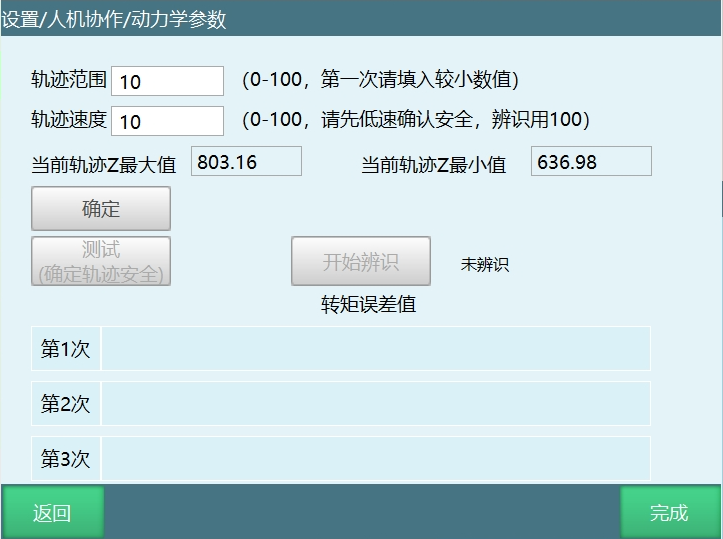
- After entering the identification operation interface, fill in the trajectory range and trajectory speed.
- Click "OK", check the current trajectory Z max and Z min values, confirm the range is reasonable and the trajectory is reachable, then proceed to the next step.
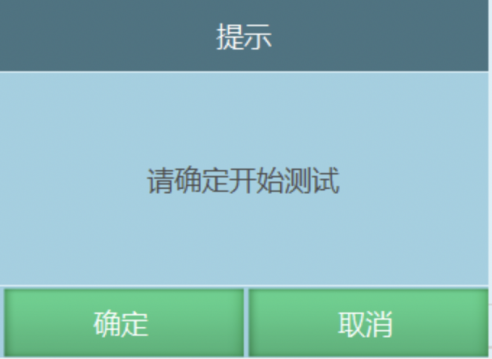
- Click "Test (Confirm Trajectory Safety)". A test prompt window will appear. After clicking "OK", if an error occurs (robot position is not at zero point), first move the robot to the zero point position, then click "Test (Confirm Trajectory Safety)" again.
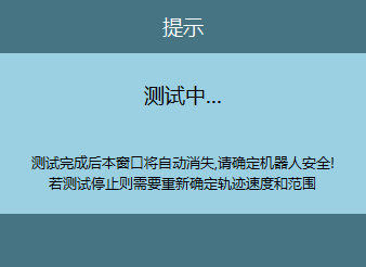
Step 3: Trajectory Test
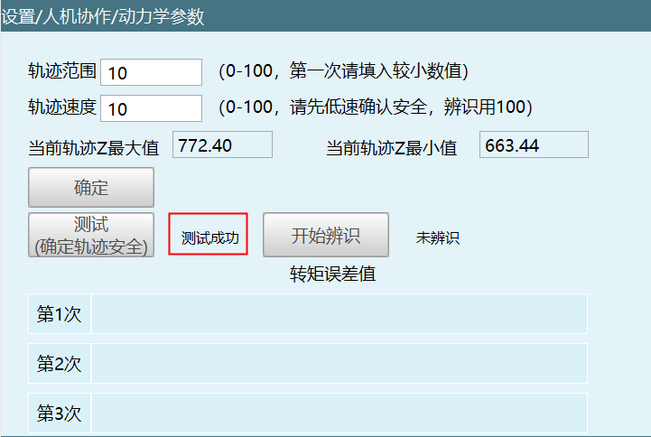
- After the trajectory test is complete, a test success prompt appears.
- If the trajectory range is small, increase the trajectory range. In principle, the larger the trajectory range, the higher the identification accuracy.
Step 4: Start Identification
After the trajectory test is complete, identification can begin. Maximize the trajectory range while ensuring safety. After adjusting the trajectory speed to 100, click "Start Identification".
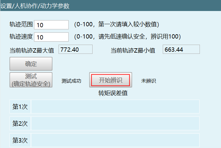
Confirm trajectory safety again, personnel stay away from the robot, click OK.
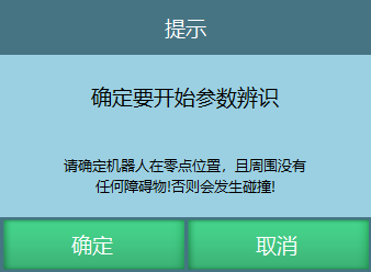
A popup indicates identification is in progress. Do not approach the robot until the identification completion prompt appears, as the robot may run the next trajectory segment at any time.
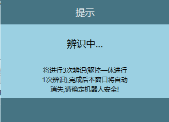
After the robot completes three identifications, the calculated torque error values for each axis will be filled in the table.
Mechanical Functions
Mechanical functions include collision detection and torque feedforward. Navigate to "Settings/Human-Robot Collaboration/Mechanical Functions" for configuration.
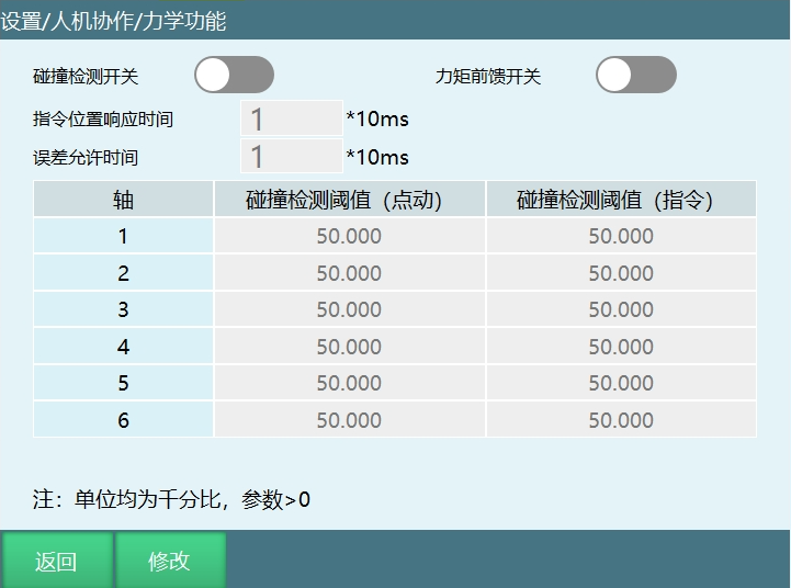
Collision Detection
| Parameter | Description |
|---|---|
| Collision Detection Switch | When enabled, the robot detects collisions based on sensitivity. Usually need to find a value that does not trigger collision detection during robot operation, then normal use is possible |
| Collision Detection Threshold (Jog) | After setting the collision detection threshold parameter, the robot will use this value when performing jog operations in teach mode |
| Collision Detection Threshold (Instruction) | After setting the parameter, the robot will use this value when returning to position, homing, stepping, trial running in teach mode, and when running after switching to run mode |
| Instruction Position Response Time | The robot body has already made contact during operation, but due to this time setting, the error report will be delayed by the set time. When the time expires, the error appears and the robot powers off |
| Error Allowance Time | PID adjustment causes torque fluctuations, triggering false collision warnings. This function prevents this phenomenon. If the torque returns to normal range within the set time, the alarm will not appear |
Torque Feedforward
The torque feedforward switch in HRC. Enabling it activates the torque feedforward function.
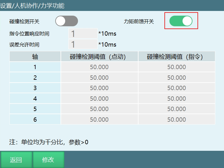
The torque transmitted from the robot controller to the motor is calculated through a specific computation, which is the robot's dynamics equation. The formula is based on Newton's laws. The dynamics equation takes the robot's posture as input, calculates the required torque, and then converts it to the corresponding motor through the Jacobian matrix.
Robot control is force-based control. Through integration of feedback force, current posture information and posture correction are obtained. Finally, the expected torque and position and speed corresponding to the corrected posture are sent to the motor driver. Through continuous iteration, the robot completes the specified actions.
In simple terms, it tells the servo in advance what torque should be used during motion, facilitating servo motion adjustment and reducing robot vibration during motion.
Hand-Guiding
Hand-Guiding Mode
External Trigger Signal: Triggers the selected IO port to enter hand-guiding mode. For example, if the signal trigger is 0, the selected IO port transitions from high level 1 to low level 0, triggering the hand-guiding signal. After IO trigger, buttons become inactive.
Hand-Guiding Method: Torque, 3D Mouse
3D Mouse Usage
This function can be used normally without identification
3D Mouse Accessories: TTL to RS232 adapter, 5V power supply, 3D mouse body, cable storage box, 3D mouse mounting plate
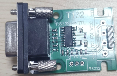
Wiring Definition
4-pin connector J1: 3DX-Sensor Module Serial has a 4-pin male connector with 1.0mm pitch. Cable connector: JSTSHR-04V-S-B with crimp contact SSH-003T-P0.2. Module connector: JSTBM04B-SRSS-TB.
| Pin # | Connector | Function Color |
|---|---|---|
| 1 | VCC +3.3V to +5.0V | Red |
| 2 | TxD (Output) | Green |
| 3 | RxD (Input) | Orange |
| 4 | GND | Black |
Cable: Connection to the console can be achieved through a 4-pin female connector with 2.54mm pitch.
| Pin # | Connector | Function Color |
|---|---|---|
| 1 | VCC +3.3V to +5.0V | Red |
| 2 | GND | Black |
| 3 | TxD (Output) | Green |
| 4 | RxD (Input) | Orange |
3D Mouse Installation Components: 3D mouse body, 3D mouse cable box, mounting plate
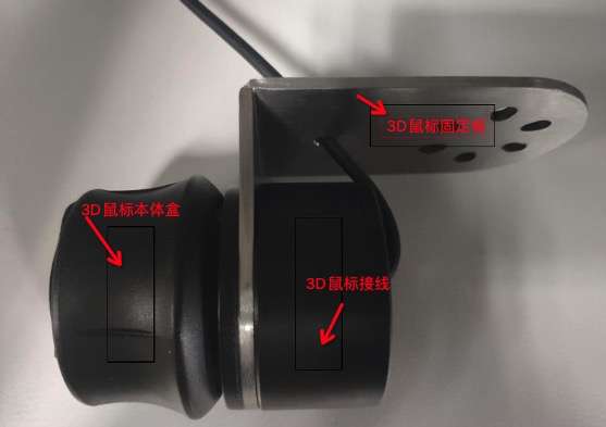
Installation Instructions: The 3D mouse cable box is used for storing part of the 3D mouse connecting cables. The mounting plate is used to install the 3D mouse on the robot end-effector. After assembling the 3D mouse components, it can be installed on the robot end-effector. The 3D mouse can also be used without being installed on the robot end-effector, but the directional sense when dragging is not as intuitive as when installed on the end-effector.
Power Supply: External 5V power supply.
Wiring Setup: Insert the mouse conversion cable into the controller's Com1 serial port. The Com1 serial port needs to support RS232 communication for direct use.
Usage Instructions and Precautions
3D Mouse Port Number: Corresponds to the COM port on the controller. Enter the number to select the corresponding COM port. The controller configuration default port number is 1. For example, with the Huahan controller, 232 uses COM2, so the controller's corresponding node needs to be changed before use.
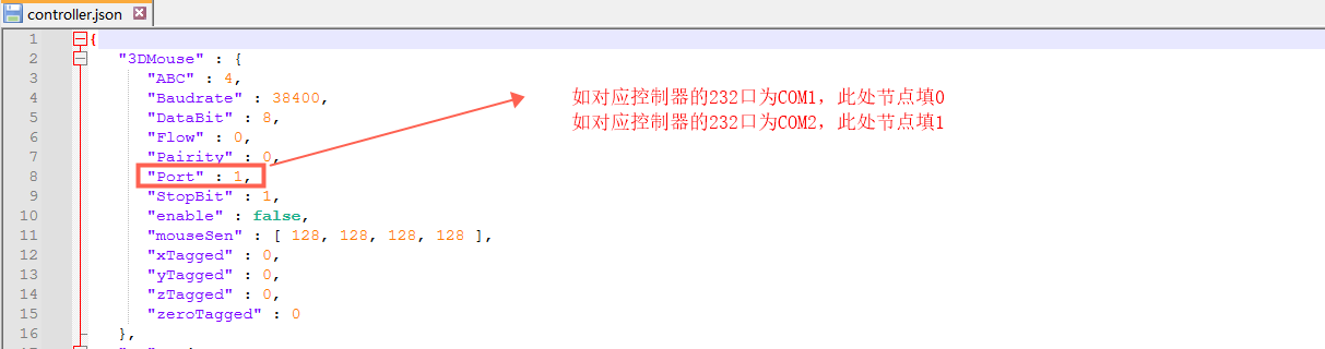
3D Mouse Parameter Settings
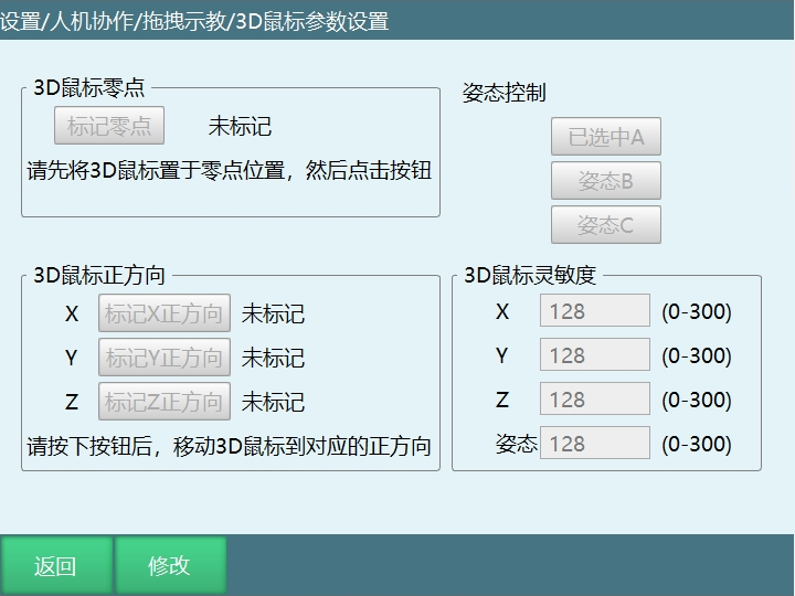
Note: If the 3D mouse is installed on the robot body, confirm robot operation safety before use.
Parameter Description:
Mark Zero Point: Must switch to hand-guiding mode before marking the 3D mouse zero position. "Unmarked" means the zero point has not been marked. "Marked" indicates it has been marked. Usage: Click Modify, then click Mark Zero Point to complete marking. No need to move the mouse.
3D Mouse Positive Direction: Divided into Mark X, Y, Z positive directions. "Unmarked" means the direction has not been marked. "Marked" indicates it has been marked. If communication fails after pressing, it will display communication failure. In this case, the direction follows the last marked direction. Usage: Click Modify, click the mark direction button, then press the corresponding direction on the mouse. A prompt indicating successful direction marking means the direction marking is complete.
Posture Control: Select the posture controlled by mouse rotation. Can choose to control posture A, B, C. Usage: Click Modify, click the corresponding posture button to complete selection.
3D Mouse Sensitivity: Controls the sensitivity of the 3D mouse in corresponding directions and postures. Usage: Click Modify, enter a value. Value range is 0-300. Higher numbers mean higher sensitivity.
First Use 3D Mouse Button Sequence: Click Modify → Mark Zero Point → Mark XYZ Direction → Set Sensitivity Value → Save
3D Mouse Robot Control Method: Complete zero point setting and direction marking → Enable servo through teach pendant → Press the corresponding direction on the 3D mouse to control the robot in that direction → The 3D mouse supports robot motion in various coordinate systems, but direction correspondence only applies to Cartesian coordinates. In other coordinate systems, joints are controlled independently, which differs from Cartesian coordinate motion.
Torque
Torque Parameter Settings
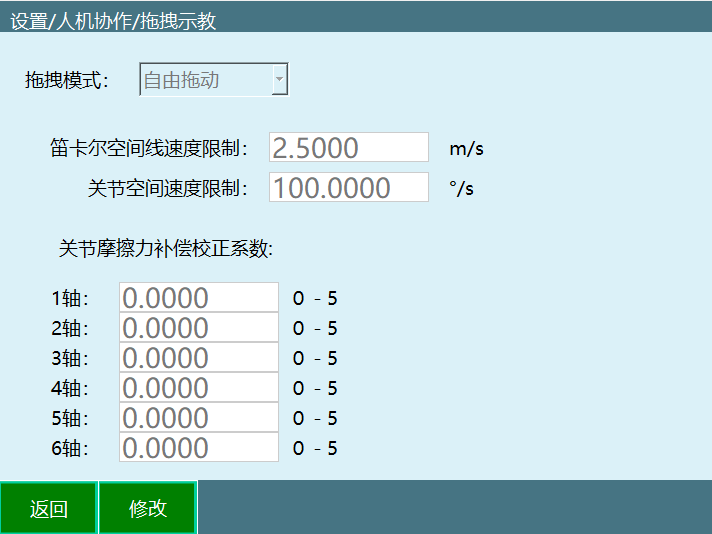
Hand-Guiding Mode has three types:
| Mode | Description |
|---|---|
| Free Drag | Can drag all six axes |
| Position Drag | Can only drag the first three axes |
| Posture Drag | Can only drag the last three axes |
Parameter Description:
| Parameter | Description |
|---|---|
| Cartesian Space Linear Speed Limit | Currently inactive |
| Joint Space Speed Limit | Maximum speed during dragging. Exceeding the limit will cause power-off and stop |
| Joint Friction Compensation Correction Factor | Range 0-5. Closer to 5 means more flexible joints. Recommend starting testing from 0 |
Switching Hand-Guiding Mode Methods
Method 1: Using Teach Pendant Shortcut Keys: Use teach pendant - Monitor - Shortcut Keys - Teaching Method button to switch.
Method 2: Using Teach Pendant Drag Key: Use the teach pendant drag key to switch.
Method 3: Using External Signal: Switch through the external signal (DIN input signal) set in Settings - Human-Robot Collaboration - Hand-Guiding interface.
Note: Before switching to hand-guiding mode, robot identification must be successful. After entering hand-guiding mode, power on to drag the robot.
Trajectory Management
Dragged trajectories are saved to this interface.
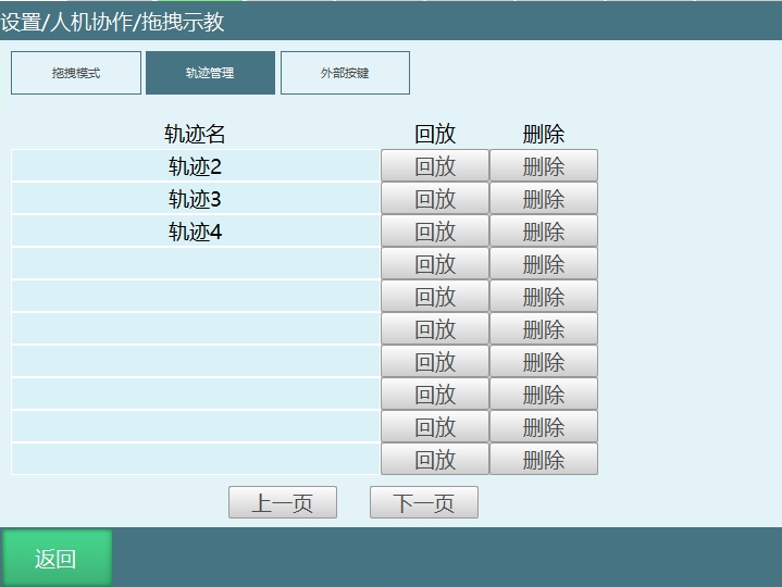
| Function | Description |
|---|---|
| Playback | Play back the dragged trajectory |
| Delete | Delete the dragged trajectory. Deleted trajectories cannot be recovered, please operate with caution |
External Buttons
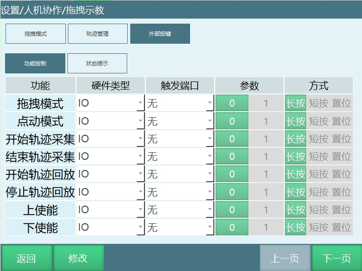
Function Control: Parameter activation method is 0 and 1.
Trigger Method is Long Press: Activates after IO is triggered for 3-10s. When 0 is effective, IO state is 1-0-1; when 1 is effective, IO state is 0-1-0.
Trigger Method is Short Press: Activates within 0-3s of IO trigger. When 0 is effective, IO state is 1-0-1; when 1 is effective, IO state is 0-1-0.
Trigger Method is Set: The IO signal for set method is continuously triggered. For normal use, select functionally opposite situations where enable 1 is effective and disable 0 is effective, bound to the same port, with method selected as Set. For example: Enable trigger port 1-1, parameter 1 effective; disable trigger port 1-1, parameter 0 effective. When port 1-1 is 1, enable; when port 1-1 is 0, disable.
Precautions: When selecting Set and the selected functions are opposite, the first parameter must be 1 and the second parameter must be 0. For example: Enable and disable functions are opposite. When set, the enable parameter must be 1, disable must be 0. If enable parameter is 0 and disable is 1, the function will not work.
Function Example:
| Function | Example Description |
|---|---|
| Hand-Guiding Mode | Example: IO port 1-1, trigger 1-1 signal, teach mode switches to hand-guiding mode Note: Robot must be successfully identified before switching to hand-guiding mode for dragging operations |
Error Code Description
Robot Identification Related
| Alarm Number | Output Type | Details | Alarm Cause | Solution |
|---|---|---|---|---|
| 20481 | Error | Robot position is not at zero point | Robot current position is not at zero point | Return robot to zero |
| 20483 | Error | Identification function only supports six-axis general robots | Robot type is not six-axis general robot | Change to six-axis serial multi-joint or six-axis collaborative for identification |
| 20507 | Error | Not identified, cannot enable dynamics function | Robot not identified | Identify robot |
| 20509 | Error | Dynamics identification does not support dual-robot | Currently in dual-robot mode | Disable dual-robot mode before identification |
| 20511 | Error | Cannot identify in hand-guiding mode | Cannot identify in hand-guiding mode | Switch to jog state for identification |
| 20512 | Error | Dynamics identification only supports Robot 1 | Can only identify in Robot 1 interface | Identify in Robot 1 |
| 20515 | Error | Error in identification process, identification stopped | Error occurred during identification | Check corresponding error, return to zero point and re-identify |
| 20518 | Error | Identification trajectory speed must be 100 | Speed should be adjusted to 100 during identification | Change trajectory speed to 100 |
| 20519 | Error | Trajectory safety check not completed | Trajectory safety test not performed | Adjust trajectory range and speed, then perform trajectory safety test |
Collision Detection Related
| Alarm Number | Output Type | Details | Alarm Cause | Solution |
|---|---|---|---|---|
| 20482 | Warning | Joint %i collision detected | Threshold during robot operation exceeds the set collision detection threshold | Increase collision detection threshold or disable collision detection |
3D Mouse Related
| Alarm Number | Output Type | Details | Alarm Cause | Solution |
|---|---|---|---|---|
| 20486 | Error | 3D mouse communication error | After importing identification parameters, drag method selected as 3D mouse, but 3D mouse not actually connected | Check wiring and corresponding configuration according to manual, connect 3D mouse |
| 20487 | Error | 3D mouse communication error, direction marking failed | 3D mouse not communicating | Check wiring and port number are correct |
| 20488 | Operation | 3D mouse direction marking successful | 3D mouse direction marking successful | 3D mouse direction marking successful |
| 20489 | Warning | 3D mouse interface changed, calibration cancelled | Exited 3D mouse settings interface to another interface during 3D mouse direction marking | Do not exit this interface during calibration process. Switch pages after calibration is complete |
| 20490 | Operation | 3D mouse zero point setting successful | 3D mouse zero point setting successful | 3D mouse zero point setting successful |
| 20491 | Error | 3D mouse zero point setting failed | 1. 3D mouse communication abnormal, not connected; 2. 3D mouse moved during zero point marking | 1. Check 3D mouse wiring and port number to ensure successful connection; 2. No need to move mouse during zero point marking |
Hand-Guiding Related
| Alarm Number | Output Type | Details | Alarm Cause | Solution |
|---|---|---|---|---|
| 20492 | Warning | No drag method selected | No drag method selected in hand-guiding interface | Enter hand-guiding interface and select corresponding drag method |
| 20493 | Error | Torque drag function only applies to UR model | Torque drag function only applies to UR model | Torque drag function only applies to UR model |
| 20494 | Error | Torque drag does not currently support this servo type | Current servo not adapted | 1. Replace with an adapted servo for identification; 2. Add current servo type to configuration before identification |
| 20498 | Operation | Drag IO triggered, entering hand-guiding mode | Entering hand-guiding mode after triggering corresponding signal | Enter hand-guiding mode after triggering corresponding IO signal |
| 20499 | Error | Servo error, exiting hand-guiding mode | OP out-of-state situation occurred in hand-guiding mode | Check Ethernet cables to confirm all servo Ethernet cables are properly connected and OP is in state |
| 20500 | Error | Torque feedforward and drag cannot be enabled simultaneously | Using torque feedforward and drag functions simultaneously | Use only torque feedforward or drag |
| 20501 | Error | Drag trajectory %s does not exist | Clicked save trajectory without starting trajectory collection | First start trajectory collection, enter trajectory name, then save |
| 20502 | Operation | Drag trajectory saved successfully | Trajectory saved after collection | Trajectory saved after collection |
| 20503 | Operation | Delete drag trajectory %s successful | Trajectory deletion effective | Trajectory deletion effective |
| 20504 | Error | Drag speed exceeds limit, changed to jog mode | Drag speed exceeds limit value in hand-guiding mode | Reduce drag speed or increase limit value |
| 20505 | Warning | Cannot execute motion operation in hand-guiding mode | Currently in hand-guiding mode, enabling jog robot | Change hand-guiding mode to jog mode, enable jog axis or drag robot in hand-guiding mode without jogging |
| 20506 | Error | Trajectory recording requires servo enabled state | Robot servo not enabled during trajectory recording | Enable servo before trajectory recording |
| 20508 | Error | Trajectory %s already exists, cannot save same name trajectory | Trajectory name not changed after collection, causing duplicate name with previously saved trajectory | Change trajectory name after collection before saving |
| 20510 | Error | Cannot set drag method in hand-guiding mode | Attempted to switch drag method in hand-guiding mode | Switch robot to jog mode before switching drag method |
| 20513 | Error | Not identified, cannot enter torque drag | Robot not identified | Enter HRC interface for dynamics identification |
| 20514 | Error | Cannot playback during trajectory recording | Clicked playback while recording trajectory is not finished | Can only playback trajectory after recording is complete |
| 20516 | Error | This function only supports one robot | Switched to hand-guiding mode in non-Robot 1 state | Switch to hand-guiding mode in Robot 1 interface |
| 20517 | Error | Cannot switch hand-guiding mode during motion | Attempted to switch hand-guiding mode while jogging robot axis in jog mode | Do not switch modes while jogging robot in jog mode. Wait for motion to complete before switching |
Servo Configuration Related
| Alarm Number | Output Type | Details | Alarm Cause | Solution |
|---|---|---|---|---|
| 20484 | Error | Collaborative robot config: delay parameter must be greater than 0 | Collaborative robot config: delay parameter is 0 | Change config parameter to greater than 0 |
| 20485 | Error | Collaborative robot config: encoder 2 resolution parameter error | Encoder 2 resolution parameter abnormal | Adjust encoder 2 resolution parameter range |
| 20495 | Error | eni not configured torque actual value 0X6077 | eni file missing 0x6077 | Export eni file and add 0x6077 |
| 20496 | Error | eni not configured torque target value 0X6071 | eni missing 0X6071 configuration | Export eni file, add 0X6071 configuration, re-import |
| 20497 | Error | eni not configured torque compensation value 0X60B2 | eni file missing 0x60B2 | Export eni file and add 0x60B2 |
Other Errors
| Alarm Number | Output Type | Details | Alarm Cause | Solution |
|---|---|---|---|---|
| 20520 | Error | Adaptive acceleration function only supports SCARA model | Current model does not support adaptive acceleration/deceleration | Switch to SCARA model to use adaptive acceleration/deceleration function |
Related Resources
AI Retrieval Q&A Pairs
Q: What is the purpose of robot identification?
A: Robot identification is used to set dynamics parameters so that the controller can build the robot's dynamics model, providing the foundation for collision detection, torque feedforward, and hand-guiding functions.
Q: What preparation is needed before robot identification?
A: Navigate to "Settings/Human-Robot Collaboration/Dynamics Parameters". Ensure the robot's motion range is clear and free of obstacles. First perform a trajectory test to confirm safety before starting identification.
Q: How to enter hand-guiding mode?
A: There are three methods: 1. Use teach pendant - Monitor - Shortcut Keys - Teaching Method button to switch; 2. Use the teach pendant drag key to switch; 3. Switch through the set external signal (DIN input signal). Note: Robot identification must be successful before switching.
Q: What types of hand-guiding modes are there?
A: Hand-guiding mode has three types: Free Drag (can drag all six axes), Position Drag (can only drag the first three axes), Posture Drag (can only drag the last three axes).
Q: What preparation is needed before using the 3D mouse?
A: First use steps: Click Modify → Mark Zero Point → Mark XYZ Direction → Set Sensitivity Value (0-300) → Save. The 3D mouse can be used without robot identification.
Q: What to do if the 3D mouse cannot connect?
A: Check if wiring is correct, COM port settings are correct, and power supply is normal. The controller default port number is 1. Ensure Com1 serial port supports RS232 communication.
Q: How to adjust collision detection threshold?
A: Collision detection threshold needs to be adjusted based on actual conditions: jog mode threshold can be set lower (more sensitive), instruction mode threshold can be set higher (more stable).
Q: What to do about false collision detection triggers?
A: Possible causes include threshold set too low, robot load changes, PID adjustment causing torque fluctuations, etc. Can reduce false triggers by adjusting the error allowance time parameter.
Q: What is the function of torque feedforward?
A: Torque feedforward calculates and informs the servo of the required torque in advance before servo motion, helping the servo adjust motion and reducing robot vibration during movement.
Q: Can torque feedforward and drag functions be enabled simultaneously?
A: No, torque feedforward and drag functions cannot be enabled simultaneously. Only one of the two functions can be used at a time.
Q: How to determine if robot identification was successful?
A: After identification is complete, the interface displays error values for all six axes with no error messages, indicating successful identification. Smaller error values are better, but cannot be 0.
Q: What to do if the robot suddenly stops in hand-guiding mode?
A: Check whether collision detection was triggered, whether speed limit was reached, whether there is external signal interference, or whether servo connection is normal.
Q: Which robots is the HRC function applicable to?
A: Mainly applicable to six-axis robots. Dynamics identification only supports six-axis general robots. Torque drag function only applies to UR model.
Q: How to improve hand-guiding precision?
A: Ensure robot identification is successful with small error values, adjust appropriate joint space speed limits, and select the appropriate hand-guiding mode.
Q: What is the difference between 3D mouse and torque drag?
A: The 3D mouse can be used without robot identification and is intuitive to operate. Torque drag requires successful identification before use and is suitable for precise teaching operations.
Q: How to manage drag trajectories?
A: Dragged trajectories are saved to the trajectory management interface, supporting playback and delete functions. Trajectory collection must be performed before saving trajectories.