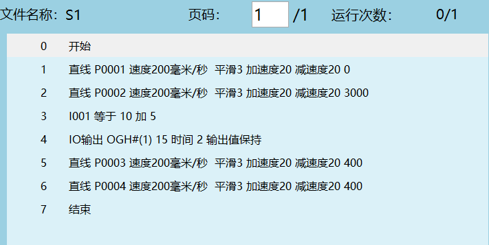
Motion Control Instructions
Motion Control Types:
"✔" indicates support for this instruction.
| Instruction Type | Foreground | Global Background | Local Background |
|---|---|---|---|
| Point-to-Point | ✔ | ||
| Linear | ✔ | ||
| Arc | ✔ | ||
| Full Circle | ✔ | ||
| Curve | ✔ | ||
| Incremental | ✔ | ||
| External Axis Point-to-Point | ✔ | ||
| External Axis Linear | ✔ | ||
| External Axis Arc | ✔ | ||
| External Axis Curve | ✔ | ||
| Global Speed | ✔ | ✔ | ✔ |
| Fixed-Point Move | ✔ | ||
| Dual-Robot Point-to-Point | ✔ | ||
| Dual-Robot Linear | ✔ | ||
| Dual-Robot Arc | ✔ | ||
| Dual-Robot Full Circle | ✔ | ||
| External Point | ✔ | ||
| External Axis Following | ✔ | ||
| Electronic Gear | ✔ | ||
| Reset External Axis Multi-Turn | ✔ | ||
| Trajectory Playback | ✔ | ||
| Switch Payload | ✔ | ||
| Arch Motion | ✔ | ||
| Extended Arch | ✔ | ||
| External Reference Point Linear | ✔ | ||
| External Reference Point Arc | ✔ | ||
| External Reference Point Full Circle | ✔ |
How to insert an instruction? Method as follows:
- Click Project, click [New];
- After creating a new program, click [OK];
- Enter the program instruction interface, click [Insert];
- Enter the instruction type interface, select the instruction type to insert, then select the instruction and click [OK];
- Enter the instruction parameter setting interface. If you need to modify parameters, click [OK] after modification. If no modification is needed, click [OK] directly;
- To modify an instruction, select the instruction line to modify in the instruction parameter interface and click [Modify];
- To delete an instruction, select the instruction line to delete in the instruction parameter interface and click [Delete];
- Click [Operation] to copy, paste, cut, move up, move down, comment out, or run from the selected instruction;
- Click [Modify Position] to write the robot's current position into the selected position variable.
For detailed information about speed, smoothing, acceleration ratio, deceleration ratio, and pre-execution parameters, refer to the motion instruction parameters section.
Note: When modifying the speed of some instructions (MOVJ, MOVL, MOVS, and other motion instructions), the acceleration ratio and deceleration ratio will automatically display in a 1:1 ratio with the speed. If you need to modify the acceleration ratio or deceleration ratio, you can do so manually.
MOVJ - Point-to-Point
Format: MOVJ [Instruction Name] P/GP [Variable] VJ [Speed] PL [Smoothing] ACC [Acceleration Ratio] DEC [Deceleration Ratio] TIME [Pre-execution Time, displays as 0 if not set].
Function: Used for unconstrained trajectory segments when the robot moves to the target point. The robot moves from one point to another at the fastest speed in space.
Parameters:
| Position | Uses local position variable (P) or global position variable (GP). When the value is "New", inserting this instruction creates a new P variable and records the robot's current position into this P variable |
|---|---|
| VJ | Joint interpolation speed, range: [1,100] |
| PL | Smoothing transition level, range [0,5] |
| ACC | Acceleration ratio, range [1,100] |
| DEC | Deceleration ratio, range [1,100] |
| TIME | Pre-execution time, unit ms |
Instruction Speed Parameter Introduction
Example:
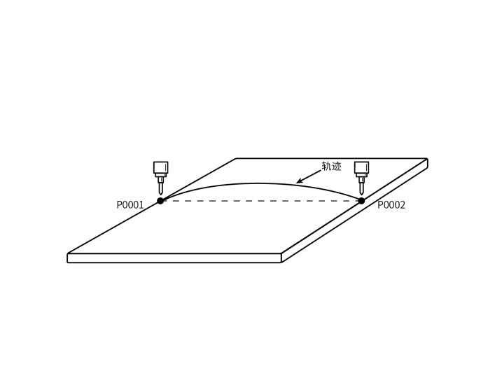
- NOP
- MOVJ P0001 VJ = 10 % PL =1 ACC = 5 DEC = 5 0
- MOVJ P0002 VJ = 10 % PL =1 ACC = 5 DEC = 5 0
- END
Example: The robot moves from P0001 to P0002 using joint interpolation.
MOVL - Linear
Format: MOVL [Instruction Name] P/GP [Variable] V [Speed] PL [Smoothing] ACC [Acceleration Ratio] DEC [Deceleration Ratio] TIME [Pre-execution Time, displays as 0 if not set].
Function: During the robot's movement to the target point, the end-effector trajectory is a straight line.
Parameters:
| Position | Uses local position variable (P) or global position variable (GP). When the value is "New", inserting this instruction creates a new P variable and records the robot's current position into the P variable |
|---|---|
| V | Linear interpolation speed, range 1-1000 (default Cartesian parameter maximum speed is 1000, range varies based on actual Cartesian parameters), unit is mm/s |
| PL | Smoothing transition level, range [0,5] |
| ACC | Acceleration ratio, range [1,100] |
| DEC | Deceleration ratio, range [1,100] |
| TIME | Pre-execution time, unit ms |
Example:
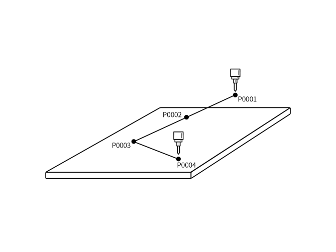
- NOP
- MOVL P0001 V = 200 mm/s PL = 0 ACC = 20 DEC=20 0
- MOVL P0002 V = 200 mm/s PL = 0 ACC = 20 DEC=20 0
- MOVL P0003 V = 200 mm/s PL = 0 ACC = 20 DEC=20 0
- MOVL P0004 V = 200 mm/s PL = 0 ACC = 20 DEC=20 0
- END
Example: The robot moves from P0001 to the target point using linear interpolation. During the movement, the end-effector trajectory is a straight line.
MOVC - Arc
Format: MOVC [Instruction Name] P/GP [Variable] V [Speed] PL [Smoothing] ACC [Acceleration Ratio] DEC [Deceleration Ratio] TIME [Pre-execution Time, displays as 0 if not set].
Function: Move to three taught points using arc interpolation.
Parameters:
| Position | Uses local position variable (P) or global position variable (GP). When the value is "New", inserting this instruction creates a new P variable and records the robot's current position into this P variable |
|---|---|
| V | Linear interpolation speed, range 1-1000 (default Cartesian parameter maximum speed is 1000, range varies based on actual Cartesian parameters), unit is mm/s |
| PL | Smoothing transition level, range [0,5] |
| ACC | Acceleration ratio, range [1,100] |
| DEC | Deceleration ratio, range [1,100] |
| TIME | Pre-execution time, unit ms |
| SPIN | Teach attitude: Attitude runs directly from the first point to the third point. Attitude inclination unchanged: Maintain the first point's inclination throughout the entire trajectory (regardless of the attitude of the second and third points). Variable representation: 0 for teach attitude, 1 for attitude inclination unchanged |
Note: To complete a full arc trajectory, the robot needs to insert one MOVJ or MOVL instruction, then two MOVC instructions. Otherwise, the program will report an error during runtime (Robot 1 instruction error, isolated MOVC instruction).
Example:
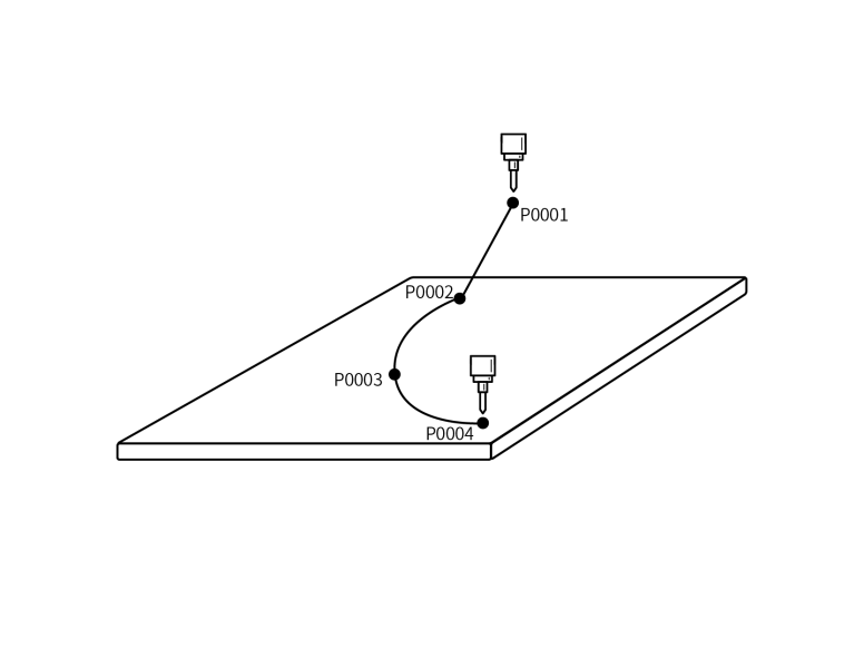
- NOP
- MOVL P0001 V=100mm/s PL=0 ACC=1 DEC=1 0
- MOVL P0002 V=100mm/s PL=0 ACC=1 DEC=1 0 Arc start point
- MOVC P0003 V=100mm/s PL=0 ACC=10 DEC=10 0 Arc midpoint
- MOVC P0004 V=100mm/s PL=0 ACC=10 DEC=10 0 Arc endpoint
- END
Example: The robot moves from P0001 to the arc start point. After reaching the arc start point, it begins the arc trajectory.
MOVCA - Full Circle
Format: MOVCA [Instruction Name] P/GP [Variable] V [Speed] PL [Smoothing] ACC [Acceleration Ratio] DEC [Deceleration Ratio] TIME [Pre-execution Time, displays as 0 if not set].
Function: The robot moves through a full circle trajectory using three taught points.
Parameters:
| Position | Uses local position variable (P) or global position variable (GP). When the value is "New", inserting this instruction creates a new P variable and records the robot's current position into this P variable |
|---|---|
| V | Linear interpolation speed, range 1-1000 (default Cartesian parameter maximum speed is 1000, range varies based on actual Cartesian parameters), unit is mm/s |
| PL | Smoothing transition level, range [0,5] |
| ACC | Acceleration ratio, range [1,100] |
| DEC | Deceleration ratio, range [1,100] |
| TIME | Pre-execution time, unit ms |
| SPIN | Attitude unchanged: The full circle trajectory maintains the same attitude as the first point's taught attitude (MOVJ, MOVL calibration attitude). Six-axis no rotation: The full circle trajectory follows each point's taught attitude, with the six axes fixed. Six-axis rotation: The full circle trajectory follows each point's taught attitude |
Note: To complete a full circle trajectory, the robot needs to insert one MOVJ or MOVL instruction, then two MOVCA instructions. Otherwise, the program will report an error during runtime (Robot 1 instruction error, isolated MOVCA instruction).
Example:
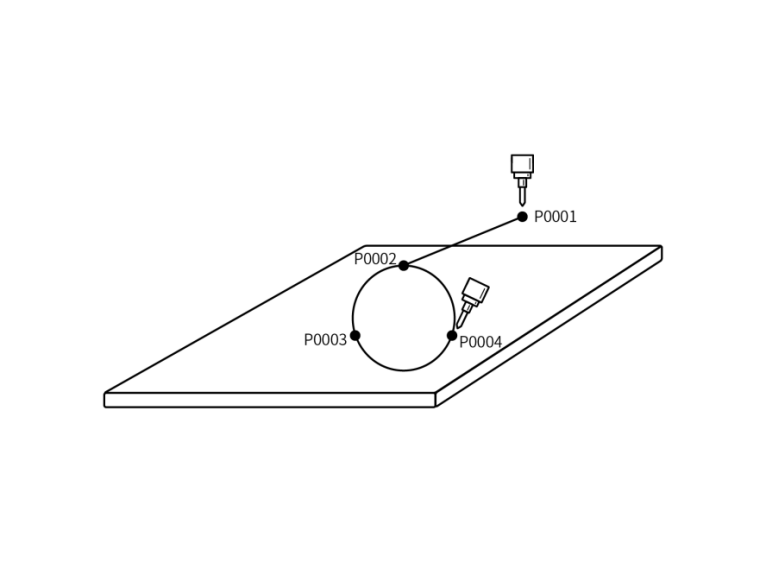
- NOP
- MOVL P0001 V=50mm/s PL=0 ACC=1 DEC=1 0
- MOVL P0002 V=50mm/s PL=0 ACC=1 DEC=1 0 Full circle start point
- MOVC P0003 V=100mm/s PL=0 ACC=10 DEC=10 0 Full circle transition point
- MOVC P0004 V=100mm/s PL=0 ACC=10 DEC=10 0 Full circle endpoint
- END
Example: The robot moves from safety point P0001 to the full circle trajectory start point P0002. After reaching the full circle start point, it begins the full circle trajectory.
MOVS - Curve
Format: MOVCA [Instruction Name] P/GP [Variable] V [Speed] PL [Smoothing] ACC [Acceleration Ratio] DEC [Deceleration Ratio] TIME [Pre-execution Time, displays as 0 if not set].
Function: During welding, cutting, fusion, primer application, and other operations, free curve interpolation makes teaching operations for irregular curve workpieces easier.
Parameters:
| Position | Uses local position variable (P) or global position variable (GP). When the value is "New", inserting this instruction creates a new P variable and records the robot's current position into this P variable |
|---|---|
| V | Linear interpolation speed, range 1-1000 (default Cartesian parameter maximum speed is 1000, range varies based on actual Cartesian parameters), unit is mm/s |
| PL | Smoothing transition level, range [0,5] |
| ACC | Acceleration ratio, range [1,100] |
| DEC | Deceleration ratio, range [1,100] |
| TIME | Pre-execution time, unit ms |
Note: A curve trajectory requires at least four taught curve points. Otherwise, the program will report an error during runtime (Robot 1 instruction error, MOVS instructions cannot be fewer than 4).
Example: Use curve interpolation to teach four points, forming a curve trajectory.
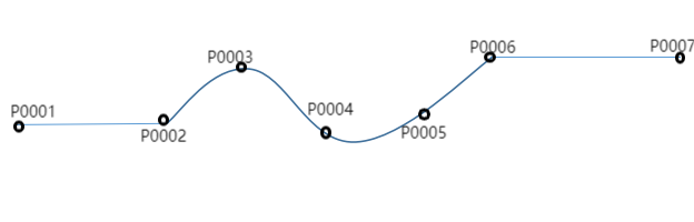
- NOP
- MOVL P0001 V = 100mm/s PL = 0 ACC = 10 DEC = 10 0 Safety point
- MOVS P0002 V = 100 mm/s PL = 0 ACC = 10 DEC = 10 0 Curve start point
- MOVS P0003 V = 100mm/s PL = 0 ACC = 10 DEC = 10 0 Curve midpoint
- MOVS P0004 V = 100 mm/s PL = 0 ACC = 10 DEC = 10 0 Curve midpoint
- MOVS P0005 V = 100 mm/s PL = 0 ACC = 10 DEC = 10 0 Curve midpoint
- MOVS P0006 V = 100mm/s PL = 0 ACC = 10 DEC = 10 0 Curve endpoint
- MOVL P0007 V = 100mm/s PL = 0 ACC = 10 DEC = 10 0 Trajectory endpoint
- END
Example: The robot moves from P0001 to the curve trajectory start point. After reaching the curve start point, it begins the curve trajectory P0002-P0006. After completing the entire curve trajectory, it moves to P0007, completing the entire motion trajectory.
IMOV - Incremental
Format: IMOV [Instruction Name] RP [Variable] V/VJ [Speed] RF BF TF UF [Coordinate System] PL [Smoothing] ACC [Acceleration Ratio] DEC [Deceleration Ratio] TIME [Pre-execution Time, displays as 0 if not set].
Function: Move a set incremental value from the current position using joint or linear interpolation.
Parameters:
| RP | Incremental variable, records incremental position data |
|---|---|
| V/VJ | V: Linear interpolation speed VJ: Joint interpolation speed |
| PL | Smoothing transition level, range [0,5] |
| Coordinate System | Joint coordinates, Cartesian coordinates, tool coordinates, user coordinates |
| ACC | Acceleration ratio, range [1,100] |
| DEC | Deceleration ratio, range [1,100] |
| TIME | Pre-execution time, unit ms |
Note: Error handling: When inserting an incremental instruction, if the coordinate system is set to tool coordinates, the position tool must match the actual tool used. Otherwise, the program will report an error during runtime (e.g., Robot 1 tool usage error, position tool is 1, actual tool is 2).
Example:
| Coordinate system can be joint, Cartesian, tool, or user. Positive values for corresponding axes indicate positive direction, negative values indicate negative direction, and 0 means no movement |
|---|
| Coordinate System |
| Joint Coordinates (RF) |
| Cartesian Coordinates (BF) |
| Tool Coordinates (TF) |
| User Coordinates (UF) |
External Axis Instructions
Question: What is an external axis?
Answer: External axes refer to axes added in addition to the robot body for work requirements. They are used in industries such as spraying, welding, and cutting.
Question: How to set up external axes?
Answer: Click Settings - Robot Parameters - Slave Configuration. In the slave list interface, click [External Axis] to enter the external axis configuration interface. Click [Modify] to set the external axis group count and external axis model, then click Save. Click [Axis Group Number] to select the external axis group in the axis group combination configuration interface.
Question: How to set external axis parameters?
Answer: Click Settings - External Axis Parameters to enter the external axis parameter interface. Calibrate the external axis. For external axis calibration methods, refer to the "External Axis User Manual". Set external axis joint parameters, etc. After completing the parameter settings, the external axis can be used for work.
Note: When modifying the speed of external axis instructions, the acceleration ratio and deceleration ratio will automatically display in a 1:1 ratio with the speed. If you need to modify the acceleration ratio or deceleration ratio, you can do so manually.
MOVJEXT - External Axis Point-to-Point
Format: MOVJEXT [Instruction Name] E/GE [Variable] VJ [Speed] PL [Smoothing] ACC [Acceleration Ratio] DEC [Deceleration Ratio] TIME [Pre-execution Time, displays as 0 if not set]
Function: The robot moves to the taught position using joint interpolation. When the external axis rotates, the robot moves on the external axis through the taught points.
Parameters:
| E | Variable that records the robot and external axis position data. When the value is "New", inserting this instruction creates a new E variable and records the current positions of the robot and external axis into this E variable. |
|---|---|
| VJ | Joint interpolation speed, range [1,100] |
| EVJ | External axis speed, range [1,100] |
| PL | Smoothing transition level, range [0,5] |
| ACC | Acceleration ratio, range [1,100] |
| DEC | Deceleration ratio, range [1,100] |
| TIME | Pre-execution time for the next instruction. Unit ms |
Example:
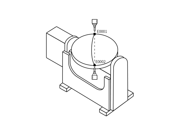
- NOP
- MOVJEXT E0001 VJ = 10 % PL = 0 ACC= 10 DEC = 10 0
- MOVJEXT E0002 VJ = 20 % PL = 0 ACC= 10 DEC = 10 0
- END
Example: The robot moves from E0001 to E0002, and the external axis rotates during the E0001-E0002 motion.
MOVLEXT - External Axis Linear
Format: MOVLEXT [Instruction Name] E/GE [Variable] V [Speed] PL [Smoothing] ACC [Acceleration Ratio] DEC [Deceleration Ratio] SYNC [Positioner synchronization, "0" means synchronization not enabled, "1" means synchronization enabled] TIME [Pre-execution Time, displays as 0 if not set]
Function: The robot moves to the taught position using linear interpolation. When the external axis rotates, the robot moves in a linear trajectory on the external axis.
Parameters:
| E | Variable that records the robot and external axis position data. When the value is "New", inserting this instruction creates a new E variable and records the current positions of the robot and external axis into this variable. |
|---|---|
| V | Linear interpolation speed, range 1-1000 (default Cartesian parameter maximum speed is 1000, range varies based on actual Cartesian parameters), unit is mm/s |
| EVJ | External axis speed, range [1,100] |
| PL | Smoothing transition level, range [0,5] |
| ACC | Acceleration ratio, range [1,100] |
| DEC | Deceleration ratio, range [1,100] |
| TIME | Pre-execution time for the next instruction. Unit ms |
| SYNC | SYNC Positioner synchronization. On: Robot and external axis collaboratively move linearly. Off: Robot moves linearly in space, external axis moves independently to the target position. |
Note: Before using the external axis linear instruction, you must select the external axis group number in the external axis calibration interface, otherwise the program will report an error during runtime. The external axis must be accurately calibrated, otherwise there will be synchronization issues between the robot and external axis when executing the external axis linear instruction.
Example:
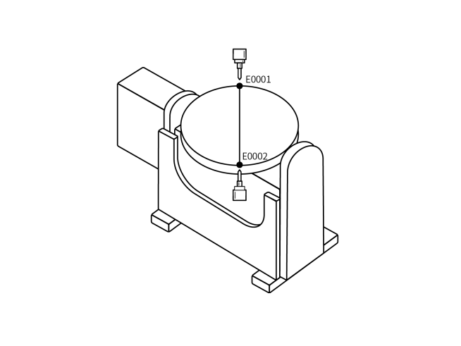
- NOP
- MOVLEXT E0001 V = 50 mm/s PL = 0 ACC = 1 DEC = 1 SYNC = 1 0
- MOVLEXT E0002 V = 50 mm/s PL = 0 ACC = 1 DEC = 1 SYNC = 1 0
- END
Example: The robot moves from the safety position to E0001. After reaching E0001, the robot and external axis collaboratively move in a linear trajectory to E0002.
MOVCEXT - External Axis Arc
Format: MOVCEXT [Instruction Name] E/GE [Variable] V [Speed] PL [Smoothing] ACC [Acceleration Ratio] DEC [Deceleration Ratio] SYNC [Positioner synchronization, "0" means synchronization not enabled, "1" means synchronization enabled] TIME [Pre-execution Time, displays as 0 if not set]
Function: The robot moves to the taught position using arc interpolation, while the external axis moves using joint interpolation. The robot end-effector moves in an arc trajectory from E0001-E0003, and the external axis rotates during the arc trajectory.
Parameters:
| E | Variable that records the robot and external axis position data. When the value is "New", inserting this instruction creates a new E variable and records the current positions of the robot and external axis into this variable. |
|---|---|
| V | Linear interpolation speed, range 1-1000 (default Cartesian parameter maximum speed is 1000, range varies based on actual Cartesian parameters), unit is mm/s |
| EVJ | External axis speed, range [1,100] |
| PL | Smoothing transition level, range [0,5] |
| ACC | Acceleration ratio, range [1,100] |
| DEC | Deceleration ratio, range [1,100] |
| TIME | Pre-execution time for the next instruction. Unit ms |
| SYNC | SYNC Positioner synchronization. On: Robot and external axis collaboratively move in an arc. Off: Robot moves in an arc in space, external axis moves independently to the target position. |
Note: Before using the external axis arc instruction, you must select the external axis group number in the external axis calibration interface, otherwise the program will report an error during runtime. The external axis must be accurately calibrated, otherwise there will be synchronization issues between the robot and external axis when executing the external axis arc instruction.
Example:
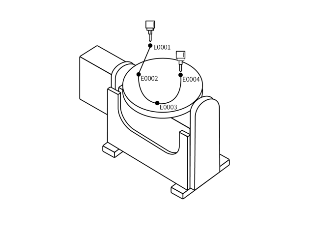
- NOP
- MOVL E0001 V = 100 mm/s PL = 0 ACC = 1 DEC = 1 0 Safety point
- MOVLEXT E0002 V = 50 mm/s PL = 0 ACC = 1 DEC = 1 SYNC = 1 0 Arc start point
- MOVCEXT E0003 V = 50 mm/s PL = 0 ACC = 1 DEC = 1 SYNC = 1 0 Arc midpoint
- MOVCEXT E0004 V = 50 mm/s PL = 0 ACC = 1 DEC = 1 SYNC = 1 0 Arc endpoint
- END
Example: The robot moves from the current position to E0001, then from E0001 to the arc start point E0002. After reaching E0002, it moves to the arc midpoint E0003, and completes the entire external axis arc trajectory at E0003. During the E0002-E0004 motion, the robot and external axis collaboratively move in an arc. As the robot moves to the taught target point, the external axis also rotates synchronously.
MOVSEXT - External Axis Curve
Function: The robot moves to the taught position using curve interpolation, while the external axis moves using curve interpolation. The robot end-effector moves in a curve trajectory from E0002-E0005, and the external axis rotates during the curve trajectory.
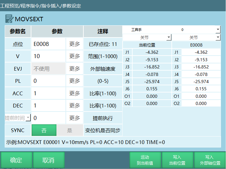
Parameters:
| E | Variable that records the robot and external axis position data. When the value is "New", inserting this instruction creates a new E variable and records the current positions of the robot and external axis into this variable. |
|---|---|
| V | Linear interpolation speed, range 1-1000 (default Cartesian parameter maximum speed is 1000, range varies based on actual Cartesian parameters), unit is mm/s |
| EVJ | External axis speed, range [1,100] |
| PL | Smoothing transition level, range [0,5] |
| ACC | Acceleration ratio, range [1,100] |
| DEC | Deceleration ratio, range [1,100] |
| Pre-execution Time | Pre-execution time for the next instruction. Unit ms |
| SYNC | SYNC Positioner synchronization. On: Robot and external axis collaboratively move in a curve. Off: Robot moves in a curve in space, external axis moves independently to the target position. |
Note: Before using the external axis curve instruction, you must select the external axis group number in the external axis calibration interface, otherwise the program will report an error during runtime. The external axis must be accurately calibrated, otherwise there will be synchronization issues between the robot and external axis when executing the external axis curve instruction.
Example:
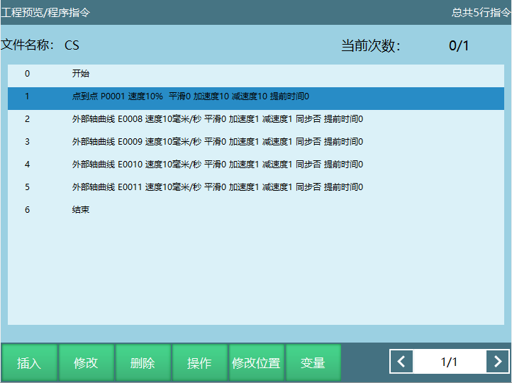
Example: The robot moves from the current position to P0001, then from P0001 to the curve start point E0008. After reaching E0008, it moves to the curve transition point E0009, and completes the entire external axis curve trajectory at E0011. During the E0008-E0011 motion, the robot and external axis collaboratively move in a curve. As the robot moves to the taught target point, the external axis also rotates synchronously.
SPEED - Global Speed
Format: SPEED [Instruction Name] 10% [Set speed parameter].
Function: Modify the speed of motion instructions under the SPEED instruction.
Parameters:
| SPEED range [1,200]% | Manual: Directly enter speed parameter. Variable: Set speed parameter by assigning a variable value. |
|---|
Note: Speed calculation for motion instructions under the SPEED instruction:
Linear speed: Instruction speed * Status bar speed * SPEED global speed percentage.
Axis speed: Joint rated positive speed * Instruction speed * Status bar speed * SPEED global speed percentage.
During program execution, you can view the current speed and maximum speed in the Monitor - Axis Speed interface.
Example: Set global speed to 50%:
- NOP
- MOVL GP0001 V = 200 mm/s PL = 2 ACC = 20 DEC=20 0
- MOVL GP0002 V = 200 mm/s PL = 2 ACC = 20 DEC=20 0
- SPEED= 80%
- MOVL GP0003 V = 100 mm/s PL = 2 ACC = 20 DEC=20 0
- MOVL GP0004 V = 100 mm/s PL = 2 ACC = 20 DEC=20 0
- MOVL GP0005 V = 100 mm/s PL = 2 ACC = 20 DEC=20 0
- END
Example: GP0001-GP0002 linear speed: Instruction speed 200 mm/s * Global speed 50%.
GP0002-GP0004 linear speed: Instruction speed 100mm/s * Global speed 50% * SPEED global speed 80%.
SAMOV - Fixed-Point Move
Format: SAMOV [Instruction Name] AP [Variable] V/VJ [Speed] RF BF TF UF [Coordinate System] PL [Smoothing] ACC [Acceleration Ratio] DEC [Deceleration Ratio] TIME [Pre-execution Time, displays as 0 if not set].
Function: The robot moves to the set position.
Parameters:
| AP | Fixed-point move variable, records position data |
|---|---|
| V/VJ | V: Linear interpolation speed VJ: Joint interpolation speed |
| PL | Smoothing transition level, range [0,5] |
| Coordinate System | Joint coordinates, Cartesian coordinates, tool coordinates, user coordinates |
| ACC | Acceleration ratio, range [1,100] |
| DEC | Deceleration ratio, range [1,100] |
| TIME | Pre-execution time, unit ms |
Parameter Settings:
| Coordinate System | Set Position Parameter Value | Example Description |
|---|---|---|
| Joint Coordinates (RF) | J1-(10) J2-(-5) J3 J4 J5 J6 | SAMOV AP0001 VJ=10% RF PL=0 ACC=1 DEC=1 0 Robot moves to the set joint position. In joint coordinates, J1 axis coordinate is 10, J2 axis coordinate is -5, other axes unchanged. |
| Cartesian Coordinates (BF) | X-(300) Y-(0) Z-(120) A B C | SAMOV AP0002 VJ=10% BF PL=0 ACC=1 DEC=1 0 Robot moves to the set Cartesian position. In Cartesian coordinates, X axis coordinate is 300, Y axis coordinate is 0, Z axis coordinate is 120, other axes unchanged. |
| Tool Coordinates (TF) | TX-(300) TY-(0) TZ TA-(3.14) TB TC | SAMOV AP0003 VJ=10% TF PL=0 ACC=1 DEC=1 0 Robot moves to the tool position. In tool coordinates, X axis coordinate is 300, Y axis coordinate is 0, attitude axis A coordinate is 3.14rad, other axes unchanged. |
| User Coordinates (UF) | UX UY-(120) UZ-(100) UA UB UC | SAMOV AP0004 VJ=10% UF PL=0 ACC=1 DEC=1 0 Robot moves to the user position. In user coordinates, Y axis coordinate is 120, Z axis coordinate is 100, other axes unchanged. |
Note: If you do not need to move a certain axis, leave the corresponding axis coordinate blank, do not fill in 0 (if you fill in 0, the corresponding axis position will become 0 when running this instruction).
Example:
Assume the robot's current joint coordinates are (10, 20, 30, 40, 50, 60). Insert a fixed-point move instruction, select joint coordinate system, and set the axis parameters to modify.
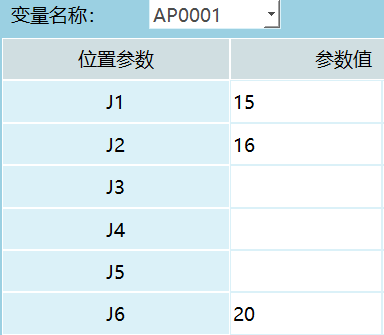
SAMOV AP0004 VJ=10% UF PL=0 ACC=1 DEC=1 0;
Example: Execute the fixed-point move instruction, and the robot moves to the target position (15, 16, 30, 40, 50, 20).
Dual-Robot Instructions
Dual-Robot Working Mode: Dual-robot collaboration is performed by two six-axis serial robots working together. Throughout the entire work process, the robots coordinate with each other to complete the final task objective.
Question: How to set up dual-robot mode?
Answer:
- Click Settings - Robot Parameters - Slave Configuration to enter the slave configuration interface, click [Robot] to enter the robot configuration interface and set the number of robots;
- Both robot types should be set to six-axis serial robots;
- Click [Save] and restart the system;
- Import configuration for Robot 1, robot_A (Robot 1 configuration) and robot_B (Robot 2 configuration);
- In Robot Parameters - Motion Parameters interface, click [Modify], enable dual-robot synchronization mode, and click [Save].
Question: How to teach positions after inserting dual-robot instructions?
Answer: Note: Dual-robot point-to-point, dual-robot linear, dual-robot arc, and dual-robot full circle instructions only support insertion in Robot 1.
- Insert dual-robot instructions in Robot 1's instruction interface;
- In Robot 1, jog the robot to the target position;
- Switch to Robot 2 and jog the robot to the target position.
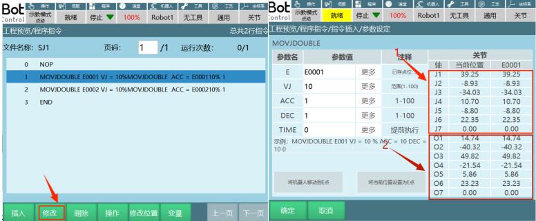
In Robot 1's program instruction interface, select the instruction to modify, click [Modify], then click [Set Current Position as E Point] in the parameter setting interface. A prompt will appear asking "Continue modifying position?". Click [OK] to store the current position into the target variable. Click [Cancel] to not record the robot's current position to the target variable. You can continue moving the robot to the desired position. Part 1 in the figure below represents Robot 1's current position and the position stored in the variable, and Part 2 represents Robot 2's current position and the position stored in the variable.
Question: How to run programs in dual-robot mode?
Answer:
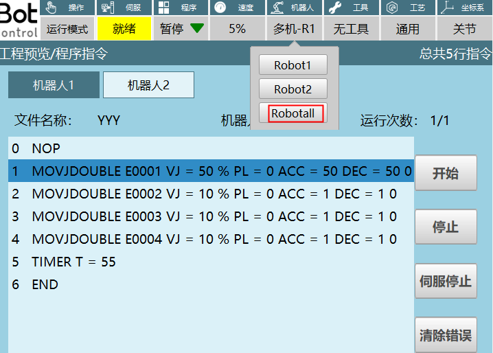
- Switch to run mode, click robot selection "Robotall" to enter the dual-robot run mode interface;
- Start both robots simultaneously by clicking [Start] on the teach pendant. To pause both robots simultaneously, click [Stop] on the teach pendant;
- To start Robot 1 individually, click [Robot 1] then click [Start] as shown in the figure. Robot 1 starts working. Click [Stop] to pause Robot 1. Robot 2's start and stop operations are the same as Robot 1.
Note: When connecting dual-robot and multi-robot, a direct connection is required. Do not use switches due to cable length issues, as this may cause the robot to experience runaway!
MOVJDOUBLE - Dual-Robot Point-to-Point
Format: MOVJDOUBLE [Instruction Name] E/GE [Variable] VJ [Speed] ACC [Acceleration Ratio] DEC [Deceleration Ratio] TIME [Pre-execution Time, displays as 0 if not set].
Function: Two robots move from one point to another using joint interpolation.
Parameters:
| E/GE | Variable that records robot position data. When the value is "New", inserting this instruction creates a new E variable and records the robot's current position into this E variable |
|---|---|
| VJ | Joint interpolation speed, range: [1,100] |
| ACC | Acceleration ratio, range [1,100] |
| DEC | Deceleration ratio, range [1,100] |
| TIME | Pre-execution time, unit ms |
Example:
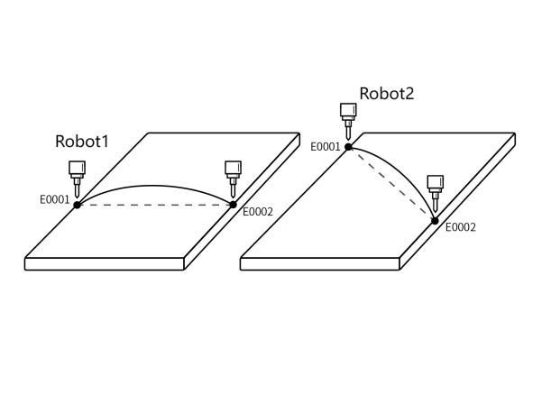
- NOP
- MOVJDOUBLE E0001 VJ = 10 % PL = 0 ACC= 10 DEC = 10 0
- MOVJDOUBLE E0002 VJ = 15 % PL = 0 ACC= 10 DEC = 10 0
- END
Example: When the program starts, both robots move from E0001 to E0002 using joint interpolation based on the taught positions.
MOVLDOUBLE - Dual-Robot Linear
Format: MOVLDOUBLE [Instruction Name] E/GE [Variable] V [Speed] ACC [Acceleration Ratio] DEC [Deceleration Ratio] TIME [Pre-execution Time, displays as 0 if not set].
Function: Control two robots to move to the target position using linear interpolation. The end-effector trajectory is a straight line.
Parameters:
| E/GE | Variable that records robot position data. When the value is "New", inserting this instruction creates a new E variable and records the robot's current position into this E variable |
|---|---|
| V | Linear interpolation speed, range 1-1000 (default Cartesian parameter maximum speed is 1000, range varies based on actual Cartesian parameters), unit is mm/s |
| ACC | Acceleration ratio, range [1,100] |
| DEC | Deceleration ratio, range [1,100] |
| TIME | Pre-execution time, unit ms |
Example:

- NOP
- MOVLDOUBLE E0001 V = 100 mm/s PL = 0 ACC= 10 DEC = 10 0
- MOVLDOUBLE E0002 V = 50 mm/s PL = 0 ACC= 10 DEC = 10 0
- MOVLDOUBLE E0003 V = 50 mm/s PL = 0 ACC= 10 DEC = 10 0
- MOVLDOUBLE E0004 V = 50 mm/s PL = 0 ACC= 10 DEC = 10 0
- END
Example: When the program starts, both robots move from E0001 to E0004 using linear interpolation based on the taught positions. The end-effector trajectory is a straight line.
MOVCDOUBLE - Dual-Robot Arc
Format: MOVCDOUBLE [Instruction Name] E/GE [Variable] V [Speed] ACC [Acceleration Ratio] DEC [Deceleration Ratio] TIME [Pre-execution Time, displays as 0 if not set].
Function: Both robots move in an arc trajectory when the program starts.
Parameters:
| E/GE | Variable that records robot position data. When the value is "New", inserting this instruction creates a new E variable and records the robot's current position into this E variable |
|---|---|
| V | Linear interpolation speed, range 1-1000 (default Cartesian parameter maximum speed is 1000, range varies based on actual Cartesian parameters), unit is mm/s |
| ACC | Acceleration ratio, range [1,100] |
| DEC | Deceleration ratio, range [1,100] |
| TIME | Pre-execution time, unit ms |
Example:
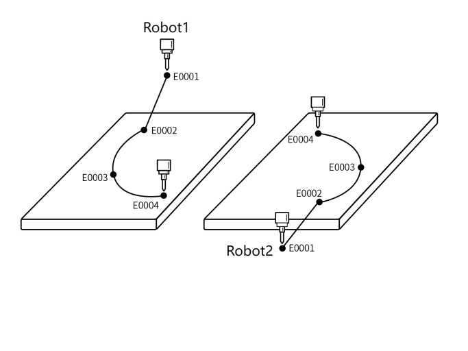
- NOP
- MOVLDOUBLE E0001 V = 10 % PL = 0 ACC= 10 DEC = 10 0
- MOVLDOUBLE E0002 V = 10 % PL = 0 ACC= 10 DEC = 10 0 Arc start point
- MOVCDOUBLE E0003 V = 100 mm/s PL = 0 ACC= 10 DEC = 10 0 Arc transition point
- MOVCDOUBLE E0004 V = 100mm/s PL = 0 ACC= 10 DEC = 10 0 Arc endpoint
- END
Example: When the program starts, both robots move from E0001 to E0002 using linear interpolation based on the taught positions, and complete the entire arc trajectory at E0002.
MOVCADOUBLE - Dual-Robot Full Circle
Format: MOVCADOUBLE [Instruction Name] E/GE [Variable] V [Speed] ACC [Acceleration Ratio] DEC [Deceleration Ratio] TIME [Pre-execution Time, displays as 0 if not set].
Function: Both robots simultaneously move in a full circle trajectory through dual-robot collaboration.
Parameters:
| E/GE | Variable that records robot position data. When the value is "New", inserting this instruction creates a new E variable and records the robot's current position into this E variable |
|---|---|
| V | Linear interpolation speed, range 1-1000 (default Cartesian parameter maximum speed is 1000, range varies based on actual Cartesian parameters), unit is mm/s |
| ACC | Acceleration ratio, range [1,100] |
| DEC | Deceleration ratio, range [1,100] |
| TIME | Pre-execution time, unit ms |
| SPIN: Robot tip rotation | Attitude unchanged: The full circle trajectory maintains the same attitude as the first point's taught attitude (MOVJ, MOVL calibration attitude). Six-axis no rotation: The full circle trajectory follows each point's taught attitude, with the six axes fixed. Six-axis rotation: The full circle trajectory follows each point's taught attitude |
Example:
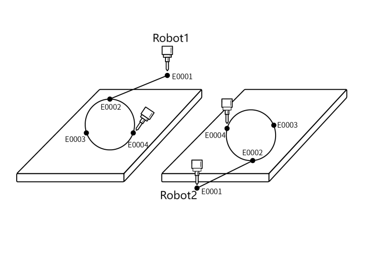
- NOP
- MOVLDOUBLE E0001 V = 10 % PL = 0 ACC= 10 DEC = 10 0
- MOVLDOUBLE E0002 V = 10 % PL = 0 ACC= 10 DEC = 10 0 Full circle start point
- MOVCADOUBLE E0003 V = 25 mm/s PL = 0 ACC= 10 DEC = 10 0 Full circle transition point
- MOVCADOUBLE E0004 V = 25 mm/s PL = 0 ACC= 10 DEC = 10 0 Full circle endpoint
- END
Example: When the program starts, both robots move from E0001 to E0002 using linear interpolation based on the taught positions, and complete the entire full circle trajectory at E0002.
Global Speed
Global speed refers to the speed displayed in the status bar on the teach pendant interface.

| Joint Jog Speed | Calculation: Joint axis maximum jog speed * Global speed |
|---|---|
| Cartesian Jog Speed | Calculation: Cartesian axis maximum jog speed * Global speed |
| Step Joint Speed | Global speed * Instruction speed * Joint rated positive speed. Maximum speed limit: Joint rated speed * 30% |
| Step Cartesian Speed | Global speed * Instruction speed. Maximum limit: 300mm/s |
| Dynamic Acceleration/Deceleration | Only supports point-to-point and linear. When speed reaches rated speed, it cannot increase further. |
| Dynamic Acceleration/Deceleration Practical Application | Modifying speed during an instruction that does not support dynamic acceleration/deceleration will apply the modified speed to the next motion instruction. |
| Trial Run Speed | Same as step instruction speed |
| Reverse Speed | Same as step instruction speed |
| Run Mode | Point-to-point: Maximum axis speed = Rated positive speed * Instruction speed * Global speed |
| Run Mode | Linear: Maximum linear speed = Instruction speed * Global speed |
| Run Mode | Curve: Uses the first curve speed as the trajectory speed |
Instruction Speed
VJ
VJ controls the motion speed of each robot joint, range: [1,100].
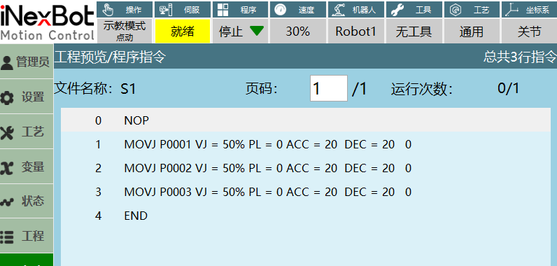
- Step joint: Maximum axis speed = Joint rated positive speed * Instruction speed * Global speed
- Run mode: Maximum axis speed = Joint rated positive speed * Instruction speed * Global speed
- Example: When executing the above MOVJ instruction, maximum axis speed = 235.17 * 50% * 30% (235.17 represents the rated positive speed of robot axis 1, used here only as an example for moving axis 1 independently)
Note: Step joint maximum speed limit is joint rated speed * 30%.
V
V is the linear motion speed of the robot end-effector in 3D space.
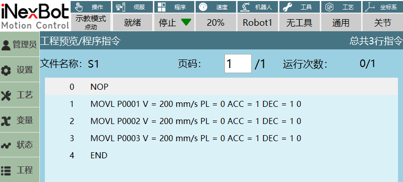
- In the Cartesian parameter interface, you can modify the maximum acceleration. The modified value will affect the linear speed range. For example: if maximum acceleration is modified to 1000, the linear speed range becomes [1,1000];
- Step Cartesian: Linear speed = Instruction speed * Global speed;
- Run mode: Linear speed = Instruction speed * Global speed;
- Note: Step Cartesian maximum linear speed is 300mm/s.
EVJ
EVJ is the external axis speed, range: [1,100], unit: %.
When both external axis and instruction speed have parameter values, the robot and external axis actually run at the smaller of the two speed parameters.
When the set external axis speed is smaller than the instruction speed, the robot and external axis execute the external axis speed when moving together.
When the instruction speed is smaller than the external axis speed, the robot and external axis execute the set instruction speed when moving together.
Welding Speed/Cutting Speed
Special processes will add process speeds.
Since welding trajectory speed is closely related to the welding process, operators may prefer to set trajectory speed from the process perspective rather than during trajectory teaching. Therefore, during welding, the welding speed in the process should replace the speed set in the trajectory.
Welding speed/cutting speed does not change according to global speed changes, always maintaining the set parameters. Welding speed/cutting speed can only be used within welding/cutting start instructions.
PL Smoothing Level
The level range: [0,5].
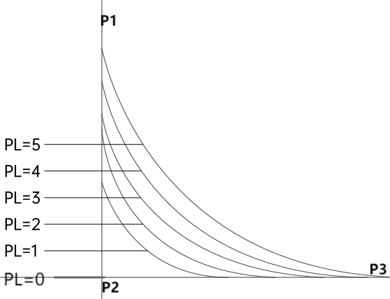
Smoothing level refers to the smoothness of robot motion at corners. If set to 0, as shown in the figure, the robot will briefly pause at corners when moving from P1 to P3. If smoothing is set, arc transitions will be used. Higher smoothing levels result in larger arcs.
ACC Acceleration Ratio, DEC Deceleration Ratio
Ratio range: [1,100].
Note: When modifying the robot's instruction speed, the acceleration ratio and deceleration ratio will change at a 1:10 ratio with the set instruction speed.
Example:
- Insert a MOVJ instruction, move only joint axis 1, then adjust the acceleration ratio and deceleration ratio parameters to obtain the robot's waveform during operation (this example only describes adjusting the acceleration ratio and deceleration ratio when moving axis 1 independently);
- Instruction parameter settings: Setting different acceleration and deceleration ratios, the waveforms collected during program execution are shown below:
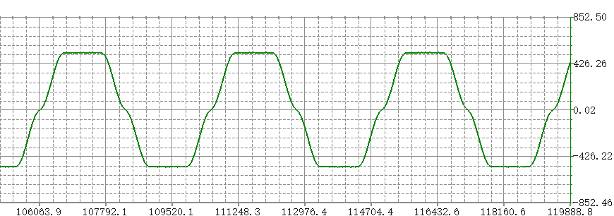
Figure 1. Global speed 50%, instruction speed 30%, acceleration ratio 10%, deceleration ratio 10%
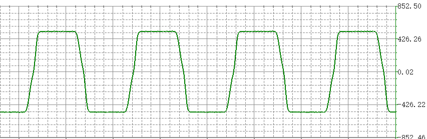
Figure 2. Global speed 50%, instruction speed 30%, acceleration ratio 50%, deceleration ratio 20%
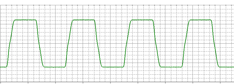
Figure 3. Global speed 50%, instruction speed 30%, acceleration ratio 20%, deceleration ratio 50%
TIME Pre-execution
Function: Pre-execute non-motion instructions.
As shown in the figure below, the second motion instruction has a pre-execution time of 3 seconds set, meaning the next instruction will execute 3 seconds in advance.
Note: Setting the pre-execution parameter will not interrupt the trajectory smoothness.