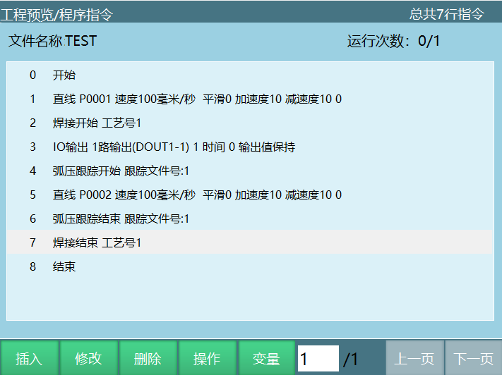
Position Tracking
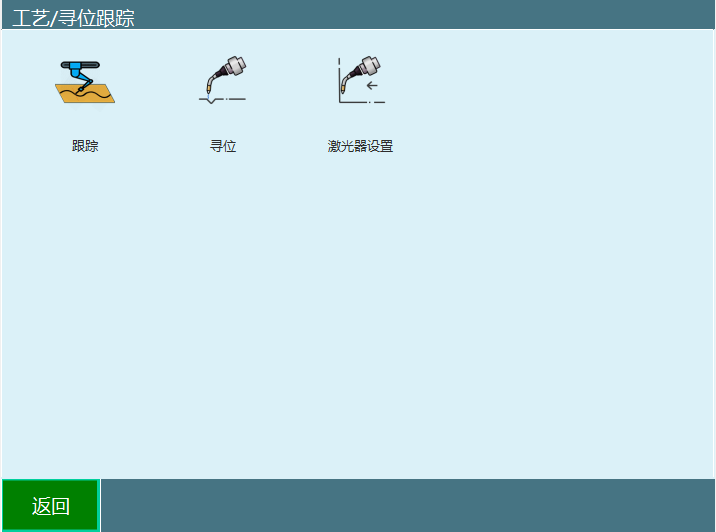
Laser Settings: Enter "Process/Position Tracking Process" to set parameters. File number corresponds to the file number in the instruction. Laser is selected based on actual usage. As shown:
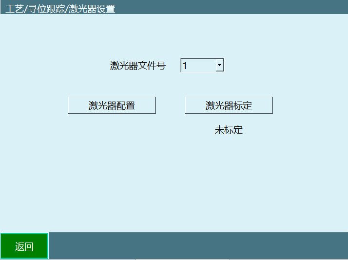
Enter "Laser Settings/Laser Configuration/" to set communication between laser and controller. As shown below:
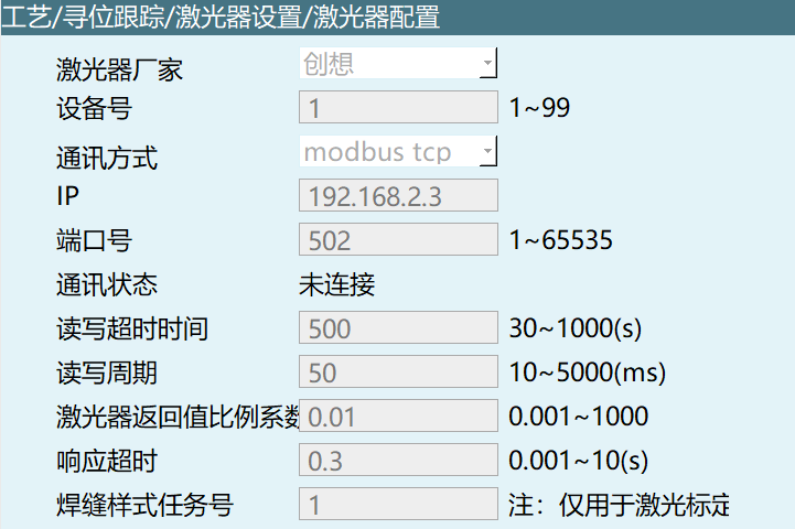
Parameter Introduction (see figure below)
Laser Manufacturer: Select the corresponding laser device name.
Device Number: Corresponding host device.
Communication Method Introduction: Through modbus communication or network communication.
IP: Connected host IP. Need to ensure controller, host, and teach pendant are on the same network segment to connect.
Port Number: Teach pendant and host port numbers need to be consistent.
Communication Status: Shows connected when laser is open.
Read/Write Timeout: Time in seconds for laser read/write before timeout occurs.
Read/Write Cycle: How many milliseconds the host performs read/write data.
Laser Return Value Scale Factor: Ratio between actual coordinate value and laser returned coordinate value.
Response Timeout: Timeout between robot query command and laser response command during laser communication.
Weld Style Task Number: Corresponds to host weld task number (only for laser calibration).
Enter "Laser Settings/Laser Calibration" to calibrate the laser. According to the figure, calibrate seven points. When first entering, a small white bar will appear in the lower right corner indicating successful laser connection. If initialization failure or connection failure is prompted, check if the manufacturer, IP, port number in laser configuration are set correctly.
During calibration, ensure the weld surface is parallel to the laser, and the laser must be perpendicular to the weld. During calibration, maintain constant posture. Also confirm that each calibration point can be seen as the intersection of weld and laser in the corresponding manufacturer's debugging software without jitter. After calibrating seven points, you can move to this position for inspection. After verification, click Calculate. If point positions are inaccurate during seeking, recalibrate the laser or tool hand. Specific interface shown below:
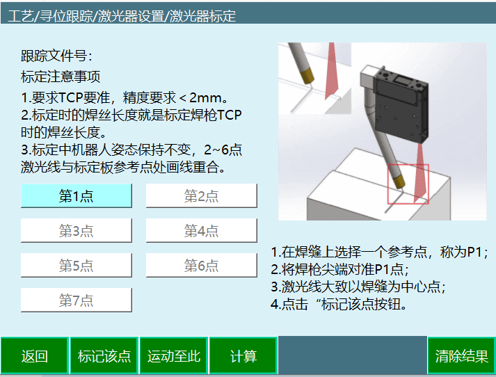
Seek Position Process
Enter "Seek Position/[Line Laser] Seek Position Parameters" for parameter settings, as shown:
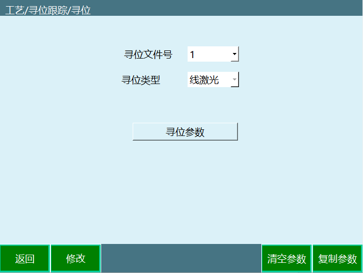
Laser Seek Position
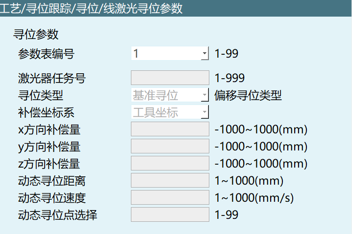
Parameter Table Number: Similar to other process numbers. Can save different user parameters and can be selected in instructions.
Laser Task Number: Corresponds to the previous device number.
Seek Position Type:
Reference Seek Position: After calibrating seek position points, the robot will convert the sought points to variables through instruction insertion and move to that point.
Correction Seek Position: Based on reference seek position, according to workpiece or weld requirements, select 1-4 point method for reference seek position. Based on different point counts, the weld can be translated left/right on the plane, rotated, and the robot tool hand can still find and follow the weld. Usually used for welding large quantities of identical workpieces in the same batch.
Compensation Coordinate System: Selectable coordinate system when compensation is needed. Tool coordinate, Cartesian coordinate.
X Direction Compensation: Compensate a certain length in the tool coordinate system at the weld position identified by the laser.
Y Direction Compensation: Compensate a certain length in the tool coordinate system at the weld position identified by the laser.
Z Direction Compensation: Compensate a certain length in the tool coordinate system at the weld position identified by the laser.
Dynamic Seek Position Distance: Distance for robot dynamic seek position. Need to visually estimate how far to reach the weld, otherwise the weld cannot be found.
Dynamic Seek Position Speed: Speed during dynamic seek position.
Dynamic Seek Position Point Selection: Based on read/write cycle and dynamic seek position distance, calculate how many points the laser will read within that distance. Also, when the laser first contacts the weld, there may be height errors or interference from non-weld gaps in other directions. These points need to be filtered out for dynamic seek position to accurately find the weld.
Laser Seek Position Tracking
Single Point Seek Position
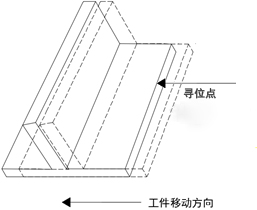
Single point seek position (two-point, three-point, four-point seek position inserts the corresponding number of static seek position instructions between seek position start and end, ensuring each static seek position has a motion point before it and the laser can find the weld on the host). Single point seek position is mainly used after robot and laser calibration for checking calibration accuracy. Implementation method: through laser point capture, give data to robot, then robot moves to point. As shown below:
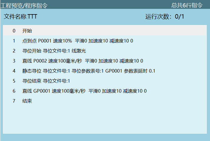
Instruction Content Introduction: (see instruction interface below)
Seek Position Start: Open laser.
Static Seek Position: Save the weld found by laser to a variable for later calculation or direct movement to point.
Seek Position End: Close laser. File number must be same as start.
Linear: Move to previously sought position point.
Two-Point Seek Position
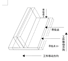
Two-point seek position is mainly used for intermittent welding, straight weld applications. Through laser capturing two points and giving point data to robot, robot moves two points forming a straight line. Two static seek position points are needed in the instruction. Schematic shown below:
Instruction Content Introduction: (see instruction interface below)
Seek Position Start: Open laser.
Static Seek Position: Save the weld found by laser to a variable for later calculation or direct movement to point.
Seek Position End: Close laser. File number must be same as start.
Linear: Move to previously sought position point.
Two-Point Seek Position Change Posture Function: Two-point seek position change posture refers to seeking one posture and welding another posture. Mainly used when seek posture interferes with workpiece during welding. Solve this problem by changing posture. Instruction same as two-point seek position, only the robot posture during seeking is different, or run through custom posture. As shown below:
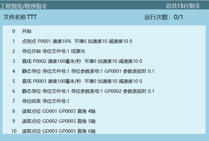
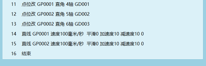
Note: Robot posture change path: Variables > Global Position Variables > Find your set global position variable parameter GP003 > Adjust to desired posture > Click write current position. The global position used here does not conflict with seek position points. Extract ABC posture values from GP0003 and assign to running points GP0001 or GP0002. As shown above.
Three-Point Arc Function
Refers to laser seeking three points on an arc, then using arc instruction to form an arc from three points. Mainly used for arc workpiece welding scenarios. Schematic shown below:
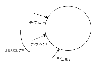
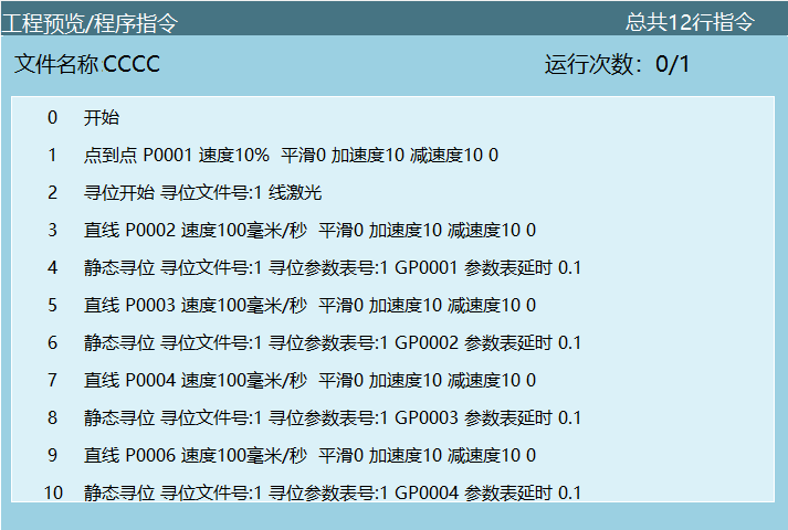
Instruction Content Introduction: (see instruction interface below)
Seek Position Start: Open laser.
Static Seek Position: Save the weld found by laser to a variable for later calculation or direct movement to point.
Seek Position End: Close laser. File number must be same as start.
Arc: Substitute the three previously sought position variables into the arc instruction, making the robot walk the arc according to sought position points. As above.

Three-Point Seek Position Calculate Coordinate System
Three-point seek position takes three points on two intersecting edges of the workpiece. Through these three points, calculate the user coordinate system. This method is used for most welding situations. If the calculated user coordinate system differs from the original, points or welds in the original user coordinate system will become points or welds in the calculated user coordinate system. Three-point offset supports one-point, two-point offset function and rotation offset. Schematic of three-point seek position shown below:
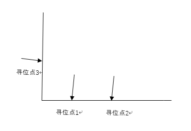
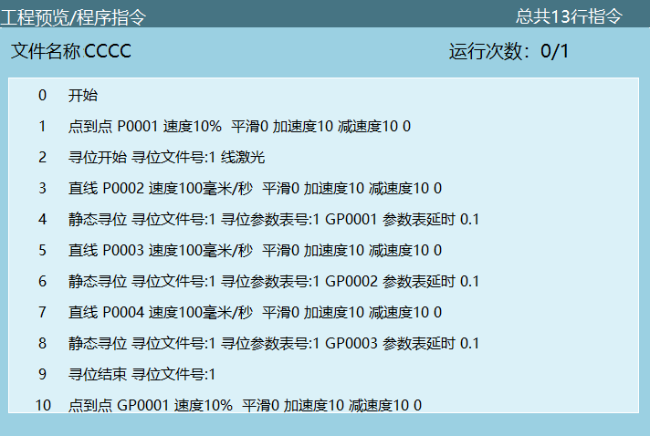
Instruction Content Introduction: (see instruction interface below)
Seek Position Start: Open laser.
Static Seek Position: Save the weld found by laser to a variable for later calculation or direct movement to point.
Seek Position End: Close laser. File number must be same as start.
Seek Position Calculation: Select 3-point calculate user coordinate system. Use three previously sought variables to calculate user coordinate system 1.
Four-Point Seek Position Calculate Coordinate System
Four-point seek position function takes four points on the workpiece, two points on any edge. Through calculation, obtain user coordinate. Each four-point seek position will produce a new user coordinate, but the trajectory within the user coordinate will not change. During four-point seek position, if every two sought points are not on the same plane of the workpiece, the overall size of the workpiece can be calculated, and then the overall user coordinate system of the workpiece can be calculated.
Schematic of four-point seek position shown below:
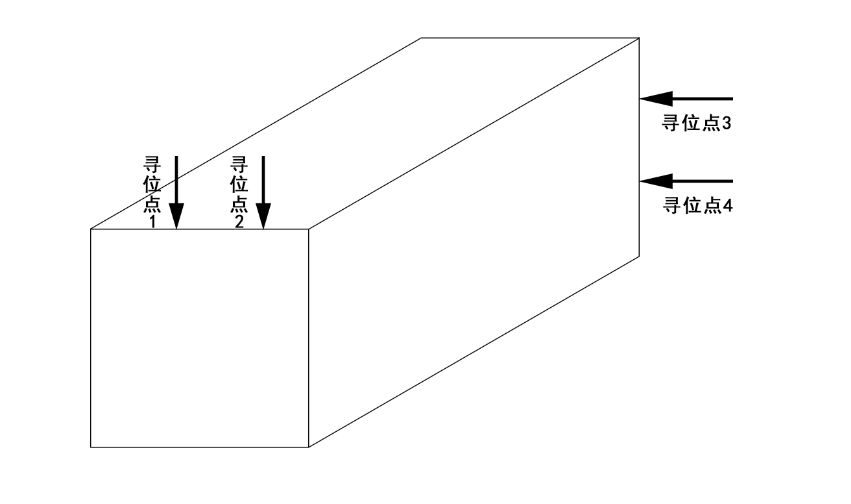
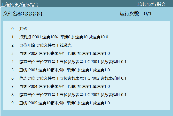
Instruction Content Introduction: (see instruction interface below)
Seek Position Start: Open laser.
Static Seek Position: Save the weld found by laser to a variable for later calculation or direct movement to point.
Seek Position End: Close laser. File number must be same as start.
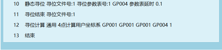
Seek Position Calculation: Select 4-point calculate user coordinate system. Use four previously sought variables to calculate user coordinate system 2.
Four-Point Determine Two Lines Calculate Intersection
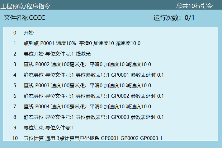
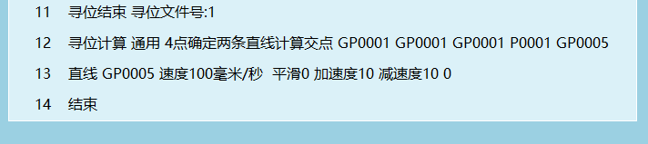
Four-point determine two lines calculate intersection takes four points on two intersecting edges of the workpiece. Two points on one edge determine a line, through the other edge determine another line, calculate the perpendicular value of two lines and record in global variables. Schematic shown below:
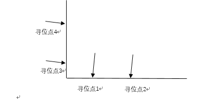
Instruction Content Introduction: (see instruction interface below)
Seek Position Start: Open laser.
Static Seek Position: Save the weld found by laser to a variable for later calculation or direct movement to point.
Seek Position End: Close laser. File number must be same as start.
Seek Position Calculation: Select 4-point determine two lines calculate intersection. Through GP0001, GP0002, GP0003, GP0004 point data, calculate projection point GP0005.
Three-Point Calculate Projection Point
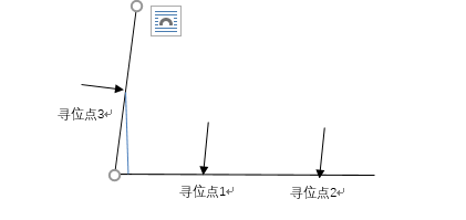
Three-point calculate projection point takes three points on two intersecting edges of the workpiece. Two points on one edge determine a line, through the projection point of the other edge's point on the line determine perpendicularity. Value recorded in global variables. Schematic shown below:
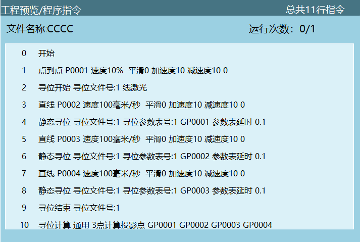
Instruction Content Introduction: (see instruction interface below)
Seek Position Start: Open laser.
Static Seek Position: Save the weld found by laser to a variable for later calculation or direct movement to point.
Seek Position End: Close laser. File number must be same as start.
Seek Position Calculation: Select 3-point calculate projection point. Through GP0001, GP0002, GP0003 point data, calculate projection point GP0004.
Linear: Move to calculated projection point.

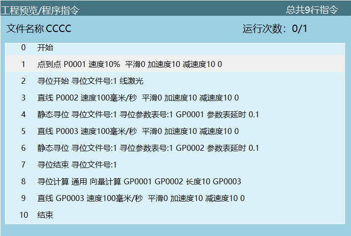
Vector Calculation
Instruction Content Introduction:
Seek Position Start: Open laser.
Static Seek Position: Save the weld found by laser to a variable for later calculation or direct movement to point.
Seek Position End: Close laser. File number must be same as start.
Seek Position Calculation: Select vector calculation. Through GP0001 to GP0002 direction select 10mm to calculate GP0003.
Linear: Move to calculated vector point.
Four-Point Calculate Plane User Coordinate System
Test purpose and effect: Through the object's shadow reflected on a plane, calculate a new user coordinate based on the shadow.
Test process:
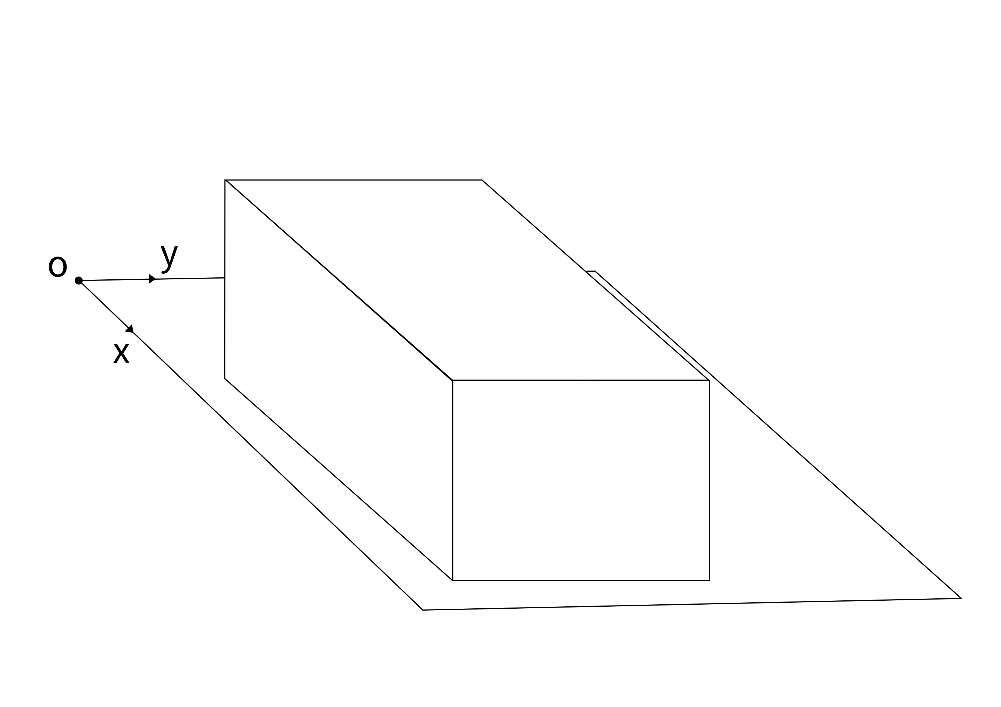
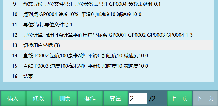
- First find a fixed plane, calibrate a basic user coordinate 1, as shown.
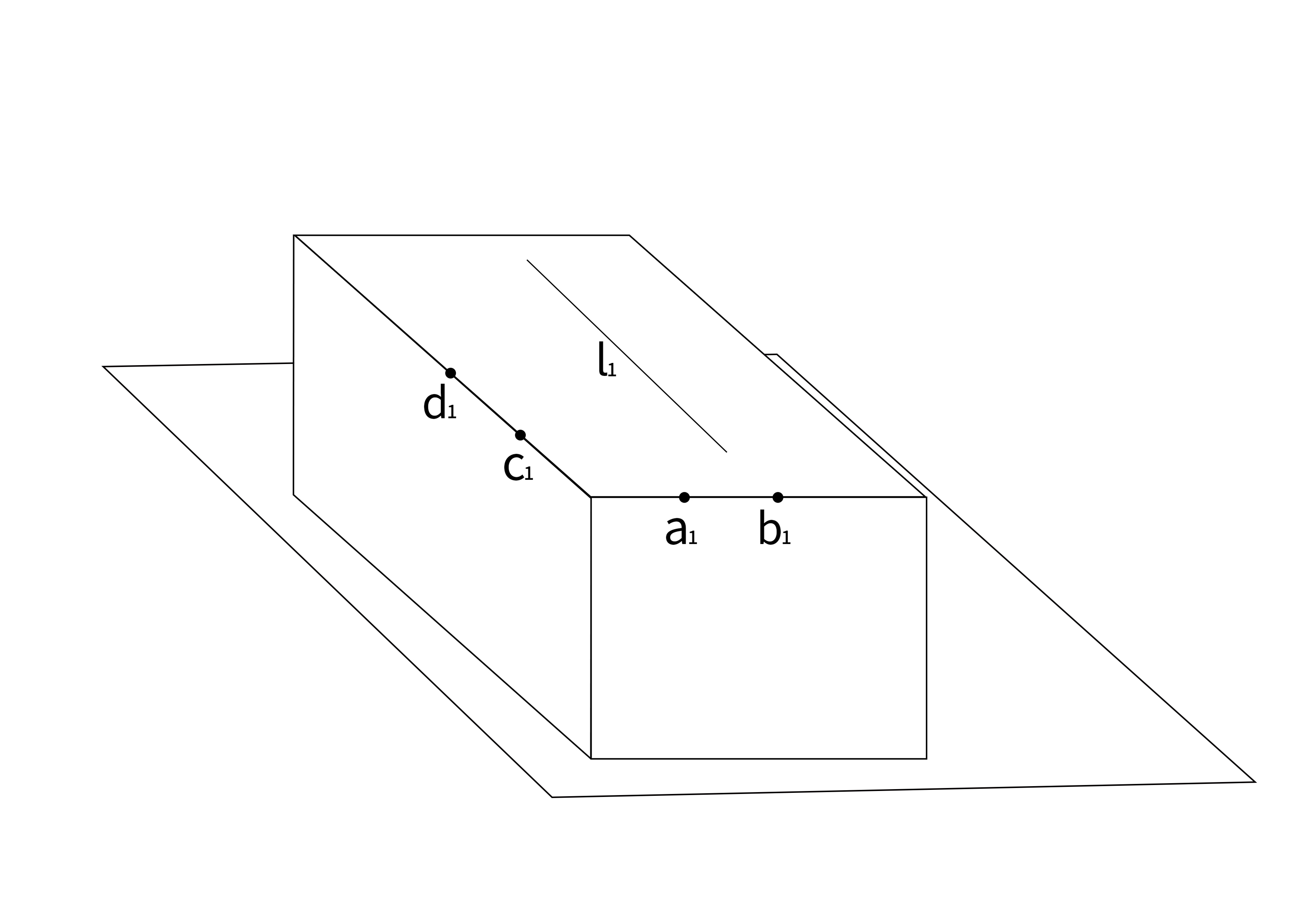
- Find two adjacent and intersecting edges on the workpiece. Use laser to calibrate two points on each edge, total four points a1, b1, c1, d1 (use laser single point seek position to calibrate each point), as shown below. After four-point calibration, calculate to obtain user coordinate 2. Need to find a weld L1 on the current workpiece for calibration (use linear).
- After above 2 steps, offset or rotate workpiece. Perform second calibration at the previously calibrated four points a2, b2, c2, d2. Calculate user coordinate 3.
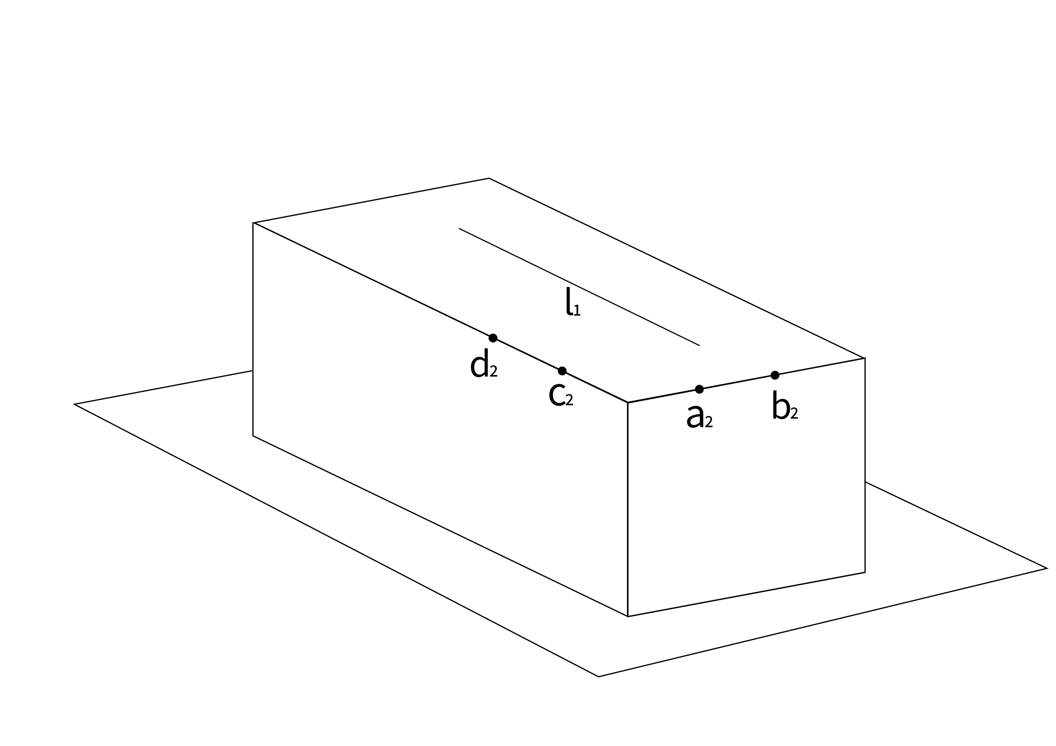
Description: Above operations must be run with tool hand.
Test instruction application:
The following figures show the instruction program process for user coordinate 2.
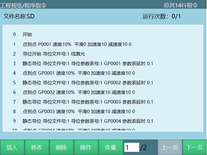
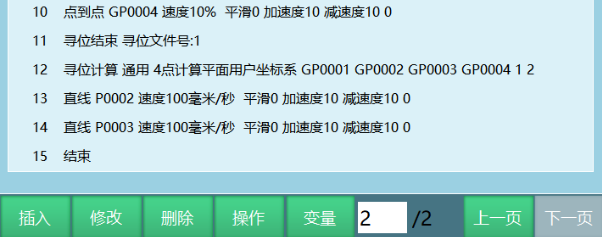
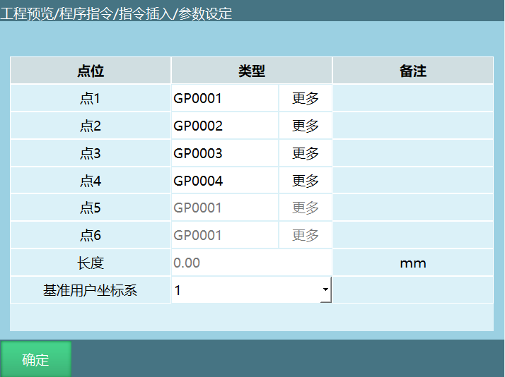
The following figures show the instruction writing process for user coordinate 3.
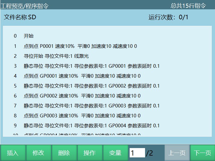
Seek Position Offset
Description: All offsets require first reference seek position then correction seek position.
One-Dimensional Offset
Usage case: After single point seek position, workpiece can only move in one direction. Seek position direction must be same as offset direction.
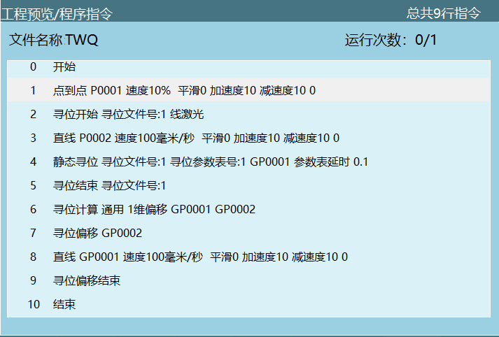
Instruction Content Introduction:
Seek Position Start: Open laser.
Static Seek Position: Save the weld found by laser to a variable for later calculation or direct movement to point.
Seek Position End: Close laser. File number must be same as start.
Seek Position Calculation: Based on sought position points and actual situation, select how many dimensions to offset. Offset G001, offset amount is G002.
Seek Position Offset: Offset is used when welding large quantities of workpieces to compensate errors. Single point to four point offsets have different uses depending on actual situation. Use calculated GP0002 offset amount to calculate GP0001 offset point position. GP0001 can be replaced with needed weld.
Two-Dimensional Offset
After two-point seek position, without workpiece rotation, only XY direction offset occurs.
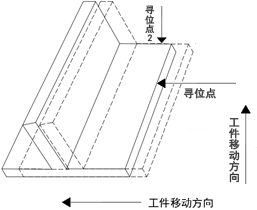
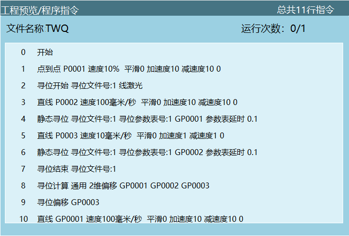

Instruction Content Introduction:
Seek Position Start: Open laser.
Static Seek Position: Save the weld found by laser to a variable for later calculation or direct movement to point.
Seek Position End: Close laser. File number must be same as start.
Seek Position Calculation: Based on sought position points and actual situation, select how many dimensions to offset. Offset GP0001, offset amount is GP0003.
Seek Position Offset: Offset is used when welding large quantities of workpieces to compensate errors. Single point to four point offsets have different uses depending on actual situation. Use calculated GP0003 offset amount to calculate GP0001 offset point position. GP0001 can be replaced with needed weld.
Two-Dimensional Offset + Rotation
After three-point seek position, workpiece can rotate overall and XY direction can offset. First perform reference seek position, then perform correction seek position when offset occurs.
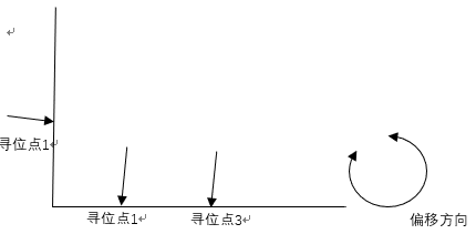
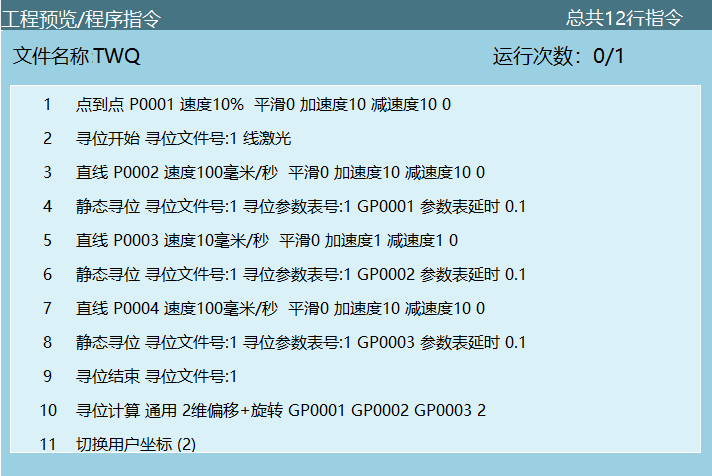

Instruction Content Introduction:
Seek Position Start: Open laser.
Static Seek Position: Save the weld found by laser to a variable for later calculation or direct movement to point.
Seek Position End: Close laser. File number must be same as start.
Seek Position Calculation: Select 2D offset + rotation, offset P0005, three points calculate user coordinate.
Switch User Coordinate System 2: Switch to calculated user coordinate system.
Linear: At this time P0005 is the previously taught user point position. It will offset based on each calculated user coordinate. P0005 can be replaced with needed weld.
Three-Dimensional Offset (Preserve Reference User Coordinate System)
After three-point or four-point seek position, workpiece can rotate overall and XY direction can offset. Two job files are needed.
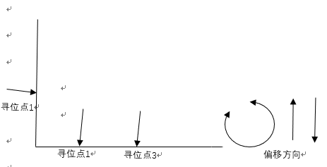
Instruction Content Introduction:
Seek Position Start: Open laser.
Static Seek Position: Save the weld found by laser to a variable for later calculation or direct movement to point.
Seek Position End: Close laser. File number must be same as start.
Seek Position Calculation: Select 3-point calculate user coordinate system, output user coordinate system 2.
Program Modification Method:
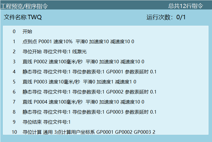
At this time, the second job file is needed. Because the previous job file is the base user coordinate system, the next job file is the user coordinate system after calculating offset. You can copy the file and add the following instructions.
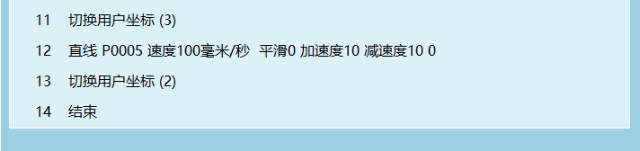
In the second job file, you must calculate a new user coordinate system and switch to the new user coordinate system before you can offset based on the difference between user coordinate systems. P0005 must be taught under user coordinate system 3 calculated after the first run. Must be a user point. P0005 can be replaced with needed weld. After that, no matter how the workpiece rotates, as long as the laser can seek 3 points, you can calculate the offset P0005. Finally, after running, you need to restore to the initial coordinate system 2 to avoid affecting subsequent user points.
Arc Seek Position
Enter "Process/Position Tracking/Seek Position/[Touch] Seek Position Parameters" to set seek position parameters, as shown:
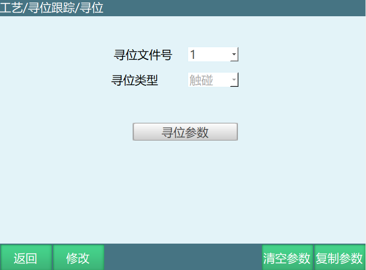
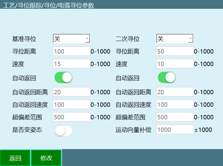
Parameter Introduction:
Seek Position File Number: Corresponds to instruction file number.
Reference Seek Position: Perform first seek position.
Secondary Seek Position: In some cases, reference seek position is not accurate enough or some manufacturers' reference seek position is too fast.
Seek Position Distance: Distance moved from instruction seek position start point.
Speed: Speed during seek position.
Auto Return: Return after welding wire touches seek position point.
Auto Return Distance: Distance to return from touching workpiece.
Change Posture: Open when performing two-point simple touch seek position calculation.
Motion Vector Compensation: During two-point simple touch seek position calculation, reverse compensate 0-5mm to prevent wire from poking into weld.
Arc Seek Position Point Introduction:
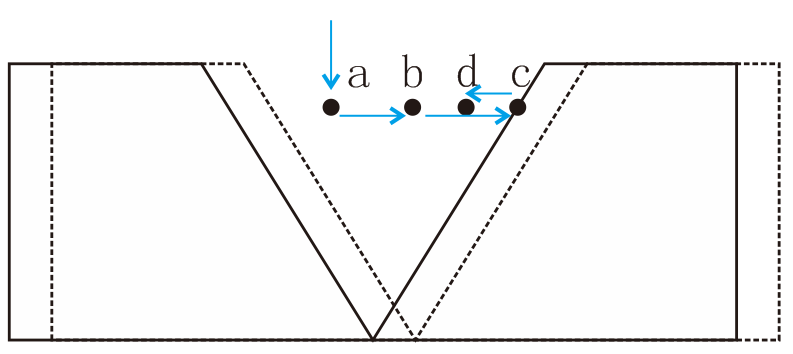
As shown: Point a is dynamic seek position preparation point; Point b is dynamic seek position start point; Robot moves along vector ab direction for seek position. Wire touches workpiece and immediately stops, indicating position found. Seek position distance (b point as start point), speed set in process parameters.
If auto return is required after seek position, robot will automatically return from c to d (return distance, speed set in parameters). Select in arc seek position process parameters: Reference seek position, configure other parameters; Run program, program will stop at seek position calculation instruction (normal), close reference seek position switch in parameters. Run program again.
Arc Seek Position Usage Types
Plane Two-Point Calculate New User Coordinate System
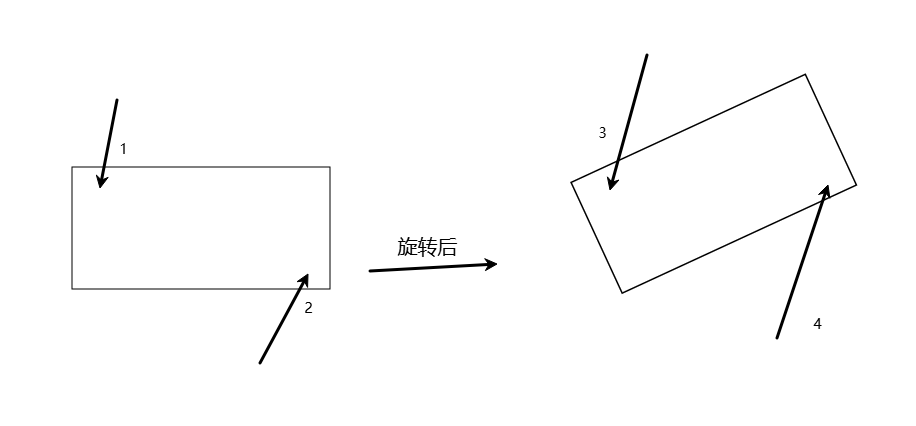
Perform user calibration before workpiece offset.
Use vision to take photo. Before workpiece offset, save two points as reference points to variables.
After offset, take photo again for total 4 points. Calculate new user coordinate system from these 4 points.
Select points based on workpiece as shown below. Adjust specific points based on actual situation.
Instructions shown below:
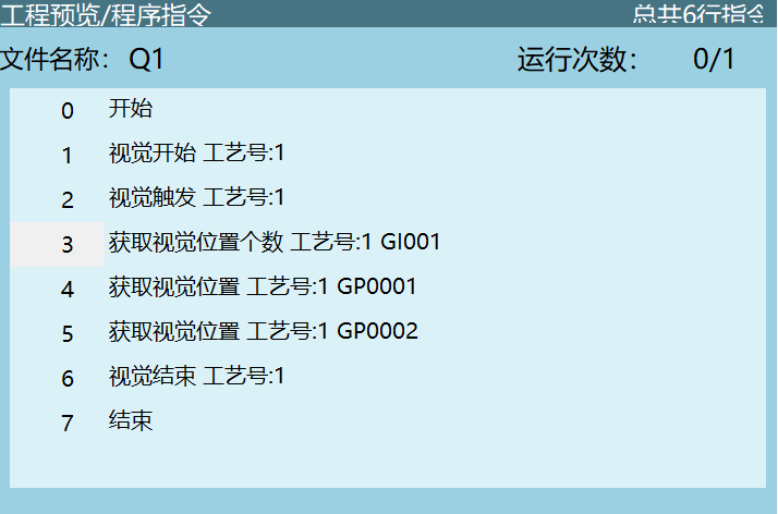
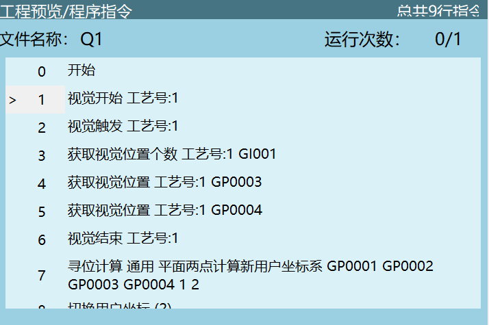

After second workpiece offset, record the two points again and save to different global position variables. Then calculate new user coordinate system from the four saved points.
2-Point Simple Touch Seek Position
Operation process: First, in the direction perpendicular to one surface of the fillet weld, dynamic seek position touch point G001. Then, in the direction perpendicular to the other surface of the fillet weld, dynamic seek position touch point G002. Then use seek position calculation instruction to calculate weld point GP003 from GP001, GP002 two points. Weld point posture is same as GP001.
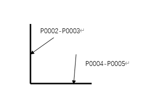
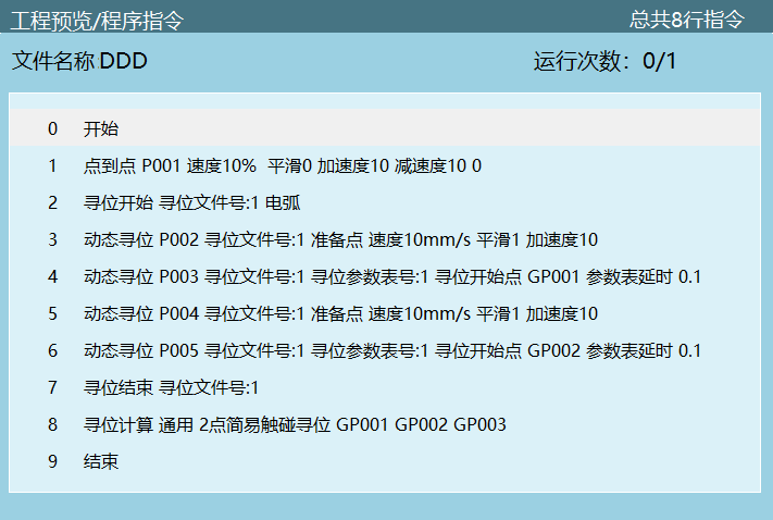
Instruction Parameter Introduction:
Seek Position Start: Open arc signal.
Dynamic Seek Position: Save the point found by arc to a variable for later calculation or direct movement to point.
Seek Position End: Close arc signal. File number must be same as start.
Seek Position Calculation: Save GP001, GP002, sought points to scalar GP003, finally calculate fillet weld weld point GP003.
Three-Dimensional Offset Plus Rotation
Operation process: Need to touch seek position on a plane to get three points, then along the edge perform touch seek position based on actual needed user coordinate system. Total six points as shown below:
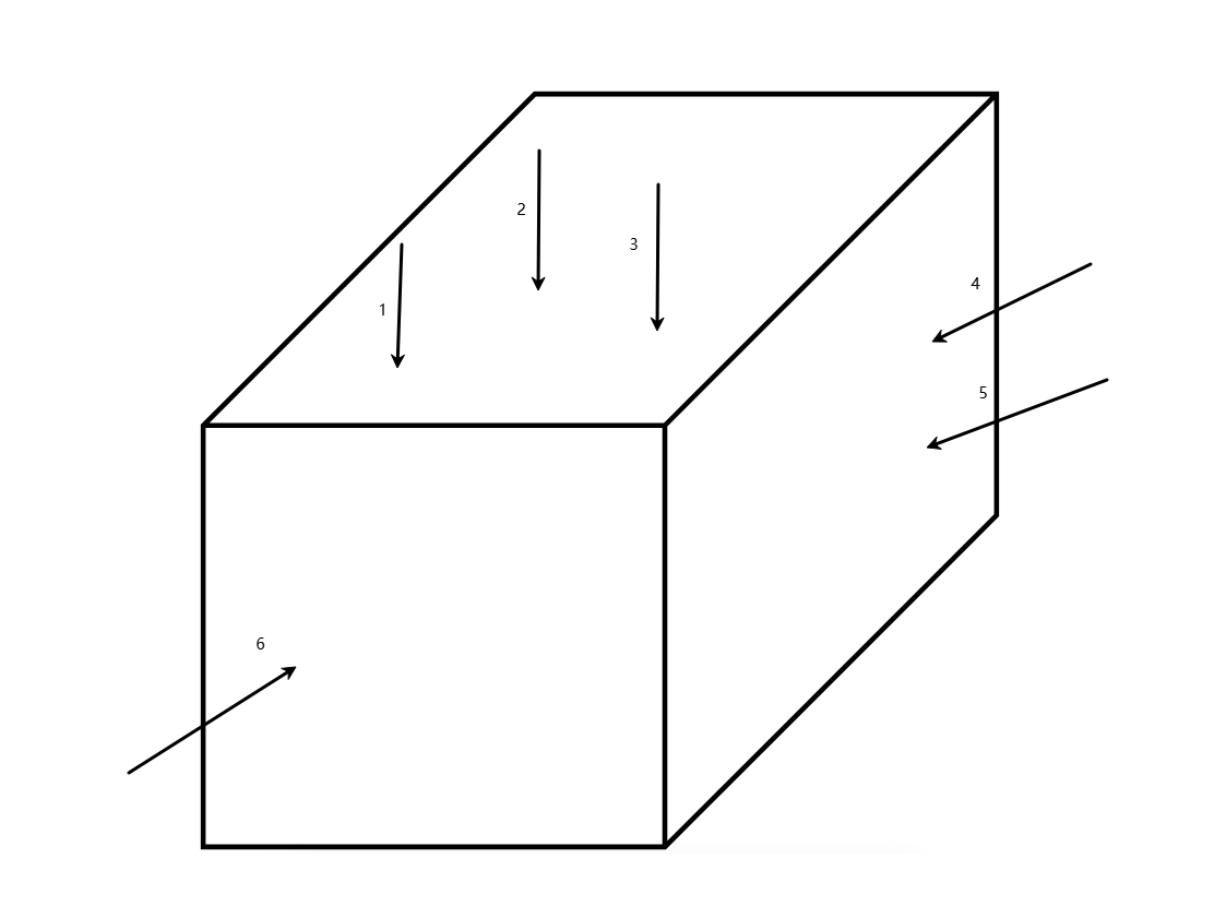
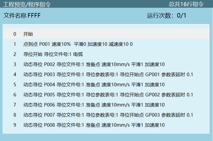
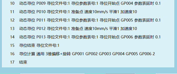
In between, based on actual situation, add point-to-point or linear as path auxiliary points. The six points found by dynamic seek position are calculated through seek position calculation 3D offset + rotation instruction to obtain user coordinate system. If offset is needed, subsequent method is same as four-point seek position. Create a same job file and teach the weld through switching user coordinate.
Line Laser Tracking
Laser Settings
Enter "Process/Position Tracking" to set parameters. File number corresponds to the file number in the instruction. Laser is selected based on actual usage.
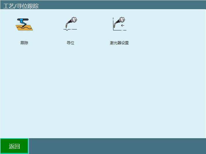
Enter "Position Tracking/Laser Settings/Laser Configuration" to set communication between laser and controller.
Laser Manufacturer: Select manufacturer based on laser model.
Device Number: Corresponding host device.
IP: Connected host IP. Need to ensure controller, host, and teach pendant are on the same network segment to connect.
Port Number: Teach pendant and host port numbers need to be consistent.
Communication Status: Shows connected when laser is open.
Read/Write Timeout: Time in seconds for laser read/write before timeout occurs.
Read/Write Cycle: How many milliseconds the host performs read/write data.
Laser Return Value Scale Factor: Ratio between actual coordinate value and laser returned coordinate value.
Response Timeout: Timeout between robot query command and laser response command during laser communication.
Weld Style Task Number: Corresponds to host weld task number (only for laser calibration).
Laser Calibration
Enter "Position Tracking/Laser Settings/Laser Calibration" to calibrate the laser. As shown:
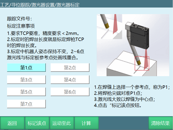
According to the figure, calibrate seven points. During calibration, ensure the weld surface is parallel to the laser, and the laser must be perpendicular to the weld. During calibration, maintain constant posture. Also confirm that each calibration point can be seen as the intersection of weld and laser in the corresponding manufacturer's debugging software without jitter. After calibrating seven points, you can move to this position for inspection. After verification, click Calculate. If point positions are inaccurate during seeking, recalibrate the laser or tool hand.
Line Laser Tracking Parameters
Enter "Position Tracking/Tracking/Line Laser Tracking Parameters" for parameter settings, as shown.
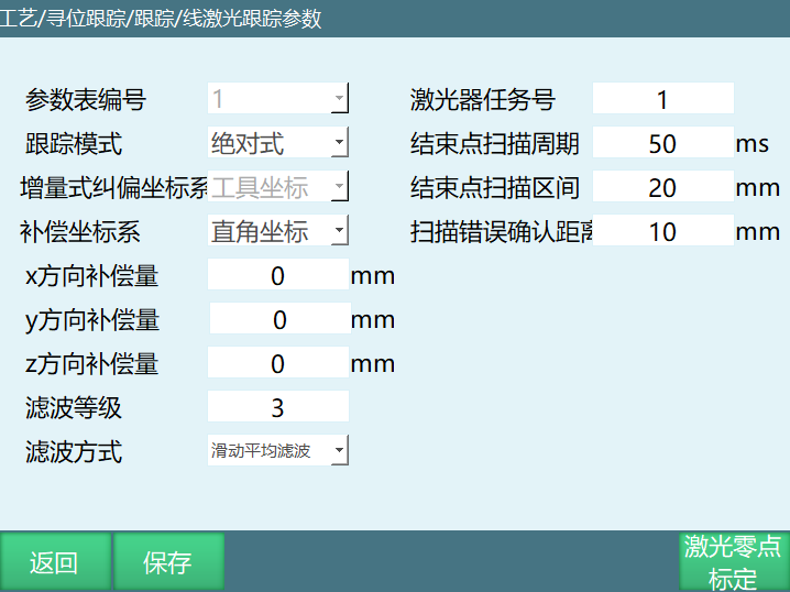
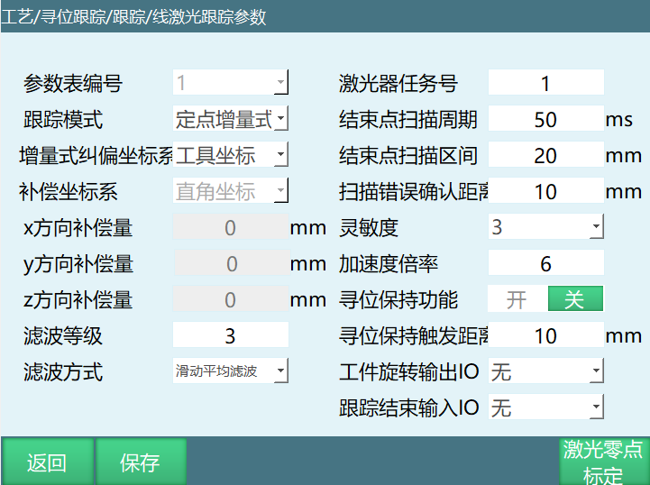
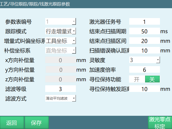
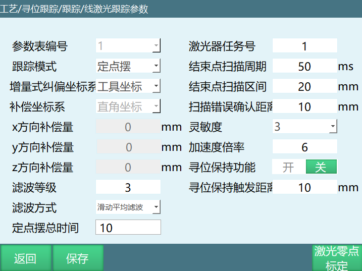
Line Laser Parameter Introduction
Parameter Table Number: Similar to other process numbers. Can save different user parameters and can be selected in instructions.
Laser Task Number: Corresponds to the previous device number.
Tracking Mode: Absolute, Fixed-point Incremental, Walking Incremental, and Fixed-point Swing.
Absolute: Precise tracking. In known weld situation, through seek position start point or directly moving near the weld for precise tracking. Precise tracking ensures that during tracking, even if the weld shifts or tool hand changes posture, as long as the laser can identify the weld, the tool hand can accurately move along the weld (currently only supports linear motion).
Fixed-point Incremental: Welding gun stays above workpiece weld. External control rotates workpiece one revolution to complete circumferential weld welding. During this process, real-time correction based on laser scanning data.
Walking Incremental: Welding gun moves along taught welding trajectory to complete welding. During this process, scanning deviation is calculated and compensated to original motion trajectory in real-time.
Fixed-point Swing: Welding gun stays above workpiece weld. Workpiece is externally controlled. Welding gun performs swing welding. During this process, real-time correction based on laser scanning data.
Sensitivity: Laser sensitivity during incremental tracking.
T/X Direction Compensation: Compensate a certain length in the tool/Cartesian coordinate system at the weld position identified by the laser.
T/Y Direction Compensation: Compensate a certain length in the tool/Cartesian coordinate system at the weld position identified by the laser.
T/Z Direction Compensation: Compensate a certain length in the tool/Cartesian coordinate system at the weld position identified by the laser.
Seek Position Hold Function: During fuzzy tracking, compensate to a certain position based on taught weld, then continuously track at that position.
Seek Position Hold Trigger Distance: Compensation distance during fuzzy tracking, suitable for short welds.
Filter Method: Smoothing algorithm for sensor data filtering.
Filter Level: Lower level means smoother, more lag.
Scan Error Confirmation Distance: During tracking, when sensor continuously fails to scan and robot moves a certain distance, report error and stop.
End Point Scan Period: Scanning period. Generally smaller period, less than 30ms.
End Point Scan Interval: Set a distance before and after the taught end point as the scan interval.
Workpiece Rotation Output IO: After welding arc start success, signal to notify third party to rotate workpiece (only exists in fixed-point incremental).
Tracking End Input IO: Workpiece welding complete, third party notifies tracking system to end tracking signal (only exists in fixed-point incremental).
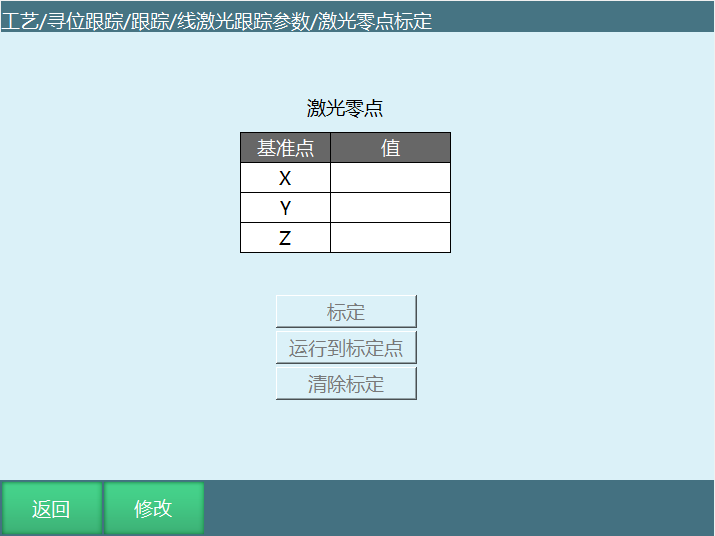
Laser Calibration Zero Point
Calibration: Calibrate laser coordinate zero point; Use the relative position of laser line and weld as the correction reference (during calibration, align welding gun with weld for calibration).
Run to Calibration Point: Move robot to the calibration point.
Clear Calibration: Clear calibration result.
Laser zero point calibration interface shown below:
Line Laser Tracking Usage
Absolute Tracking
Through teaching a straight line to determine weld direction, then use laser scanning for real-time tracking to ensure the welding gun can stay on the identified weld for welding operations. Similar to seek position, the welding gun can also change posture during tracking. If posture change is needed, just change posture at the taught point positions. Instruction interface shown below:
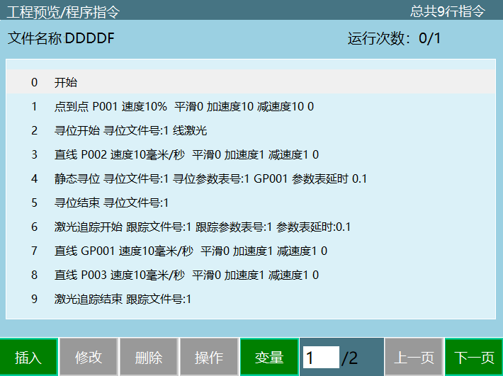
Instruction Content Introduction:
Seek Position Start: Open laser.
Static Seek Position: Save the weld found by laser to a variable for later calculation or direct movement to point.
Seek Position End: Close laser. File number must be same as start.
Laser Tracking Start: Open laser.
Linear: Move to previously sought position point.
Linear: GP001 is start point, P003 is end point. PL must be 5. If obvious acceleration/deceleration occurs, go to laser configuration and modify read/write cycle until no pause.
Laser Tracking End: Close laser. File number must be same as start.
Fixed-point Incremental
Note: Between fixed-point incremental tracking start and end, there cannot be motion instructions.
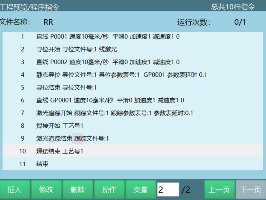
Instruction Content Introduction:
Linear: Start point.
Seek Position Start: Open laser.
Linear: Point to seek (laser line roughly at weld start point).
Static Seek Position: Save the weld found by laser to a variable for later calculation or direct movement to point (GP001).
Seek Position End: Close laser. File number must be same as start.
Linear (GP001): Move to previously sought position point (weld start point).
Laser Tracking Start: Laser sensor initialization, in-place correction, and start tracking task.
Welding Start: Welding start, third party gives arc start signal.
Laser Tracking End: Close laser. File number must be same as start.
Welding End: Welding end, third party performs arc extinguish operation.
Walking Incremental
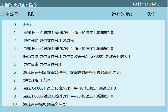

Instruction Content Introduction:
Linear: Start point.
Seek Position Start: Open laser.
Linear: Point to seek (laser line roughly at weld start point).
Static Seek Position: Save the weld found by laser to a variable for later calculation or direct movement to point (GP001).
Seek Position End: Close laser. File number must be same as start.
Laser Tracking Start: Laser sensor initialization, in-place correction, and start tracking task.
Welding Start: Welding start, give arc start signal.
Linear (GP001): Move to previously sought position point (weld start point).
Linear: GP001 is start point, P003 is end point. PL must be 5. If obvious acceleration/deceleration occurs, go to laser configuration and modify read/write cycle until no pause.
Laser Tracking End: Close laser. File number must be same as start.
Welding End: Welding end, perform arc extinguish operation.
Fixed-point Swing
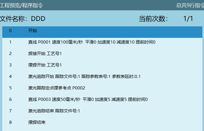

Instruction Content Introduction:
Linear (P001): Start point. (Safe point)
Welding Start: Welding start, give arc start signal.
Weave Start: Start weaving.
Laser Tracking Start: Laser sensor initialization, in-place correction, and start tracking task. Laser tracking fixed-point swing reference point (P002): End point of oscillation direction.
Linear (P003): Start point of oscillation direction.
Laser Tracking End: Close laser. File number must be same as start.
Weave End: Oscillation end.
Welding End: Welding end, perform arc extinguish operation.
Arc Tracking
Arc tracking is mainly suitable for fillet weld and V-groove weld swing welding trajectory correction. Commonly used in robot welding process for medium-thick plate welding, to correct workpiece deformation and part of workpiece assembly errors caused by high current welding.
Parameter Configuration
Enter "Process/Position Tracking/Tracking" interface, as shown below. Need to sequentially set communication parameters, left/right compensation parameters, and height compensation parameters.
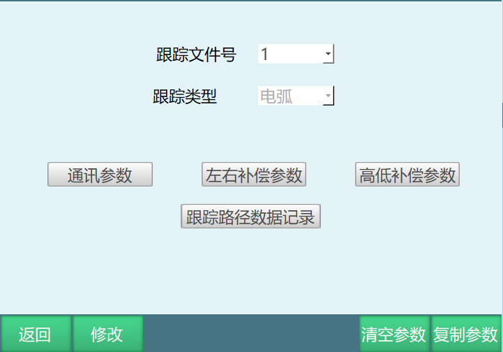
Communication Parameters
Enter "Communication Parameters" interface, as shown below. Parameter meanings:
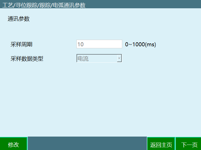
Sampling Period: Time period for collecting current/voltage signals during weaving. Recommended period 2ms~20ms.
Sampling Data Type: During weaving, select the one with larger fluctuation between voltage/current. Aotai and Megmeet recommend selecting current.
Left/Right Compensation Parameters
Left/right compensation refers to the left/right compensation of the oscillation arc trajectory on the oscillation plane. Enter "Left/Right Compensation Parameters" interface, as shown below. Parameter meanings:
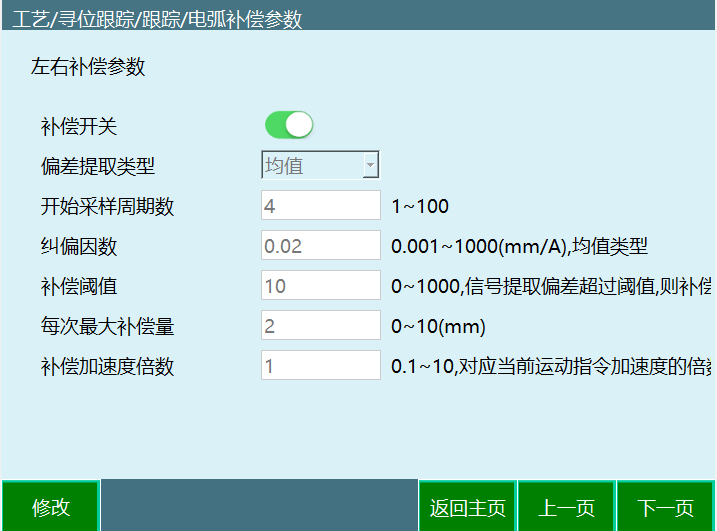
Height Compensation Parameters
Height compensation refers to the compensation in the normal direction of the oscillation plane. Enter "Height Compensation Parameters" interface, as shown below. Parameter meanings are same as left/right compensation parameters. Generally, left/right compensation is large, height compensation is small, so compensation-related parameters can be appropriately reduced.
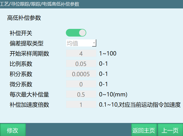
Compensation Switch: Indicates whether to perform left/right correction during weaving. Can be closed for V-groove weld weaving that only has height deviation.
Deviation Extraction Type: Currently only supports mean algorithm.
Start Sampling Period Count: At the beginning of weaving, current signal has no obvious change in the first few periods, invalid. Generally start sampling from the 3rd~5th period.
Proportional Coefficient: Proportional response to system deviation. Once deviation occurs, proportional adjustment immediately produces adjustment to reduce deviation. Larger proportional effect speeds up adjustment and reduces error, but too large proportion reduces system stability and may cause system instability.
Integral Coefficient: Eliminates steady-state error and improves astaticism. Because there is error, integral adjustment proceeds until no error, then integral adjustment stops, outputting a constant value. Integral effect strength depends on integral time constant Ti. Smaller Ti means stronger integral effect. Conversely, larger Ti means weaker integral effect. Adding integral adjustment can reduce system stability and slow dynamic response. Integral effect is often combined with other two adjustment laws to form PI or PID regulator.
Derivative Coefficient: Derivative effect reflects the rate of change of system deviation signal, with predictability. Can foresee deviation change trend, thus producing advanced control effect. Before deviation forms, it has been eliminated by derivative adjustment. Therefore, it can improve system dynamic performance. With appropriate derivative time, it can reduce overshoot and adjustment time. Derivative effect amplifies noise interference, so too strong derivative adjustment is not good for system anti-interference. Additionally, derivative reflects rate of change, and when input has no change, derivative effect output is zero. Derivative effect cannot be used alone, needs to be combined with other two adjustment laws to form PD or PID controller.
Maximum Compensation Per Time: Single cycle extracts deviation to compensate once. Maximum length per compensation. This maximum compensation prevents over-compensation caused by super large current in sampling.
Compensation Acceleration Multiplier: Acceleration for left/right compensation. Compare with correction factor. Larger correction factor means set larger, smaller correction factor means set smaller. Recommended value 1.
Tracking Path Data Recording
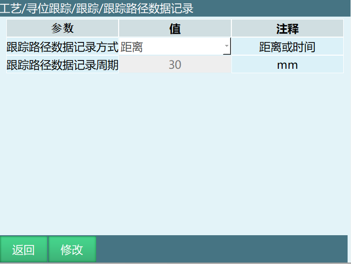
Tracking path data recording method: Distance and time.
Tracking path data recording period: This value indicates how often to record path data.
Description: Path inflection points must be recorded (as shown, not only the tracked points in the middle, start point, end point, inflection point variable names must also be recorded.
Tracking Usage Cases
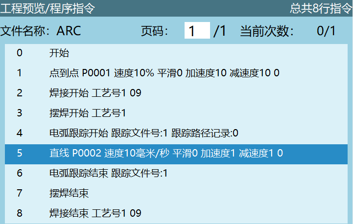
Linear Weave Tracking
Arc Weave Tracking
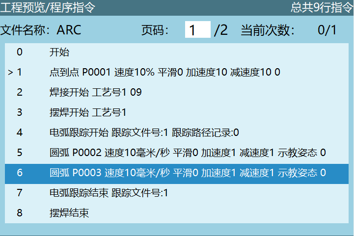

Note: P001, p002, P003 are 3 points on the arc.
Arc Voltage Tracking
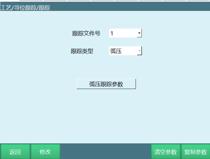
Clear Parameters: Clear parameter values set in current tracking file number.
Copy Parameters: Copy parameter values set in current tracking file number to the desired process number.
Arc Voltage Tracking Parameters
Arc Voltage Collection
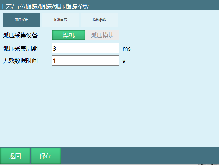
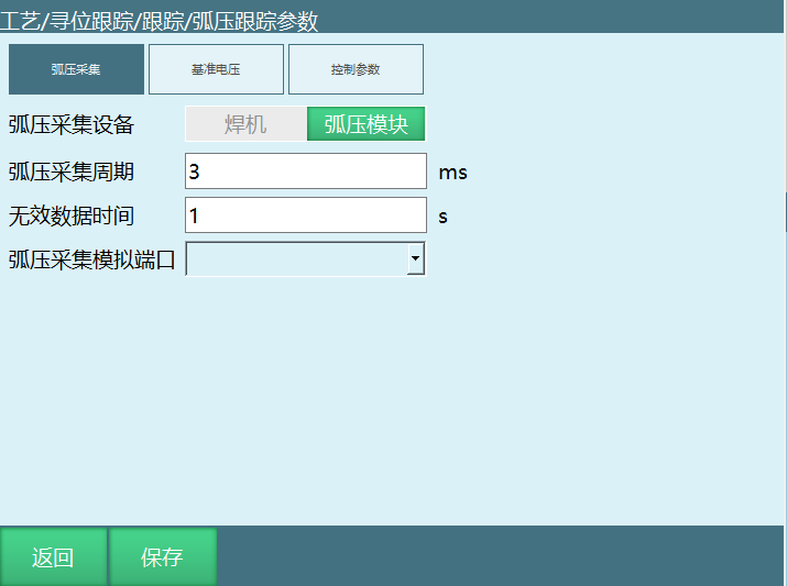
Arc Voltage Collection Device: Divided into welder and arc voltage module.
Arc Voltage Collection Period: How often to collect voltage, unit is ms.
Invalid Data Time: After welding arc start, there is a period of very high voltage that cannot be collected for calculation.
Arc Voltage Collection Analog Port: Only exists when arc voltage module is selected. Analog input port that needs to be connected.
Reference Voltage
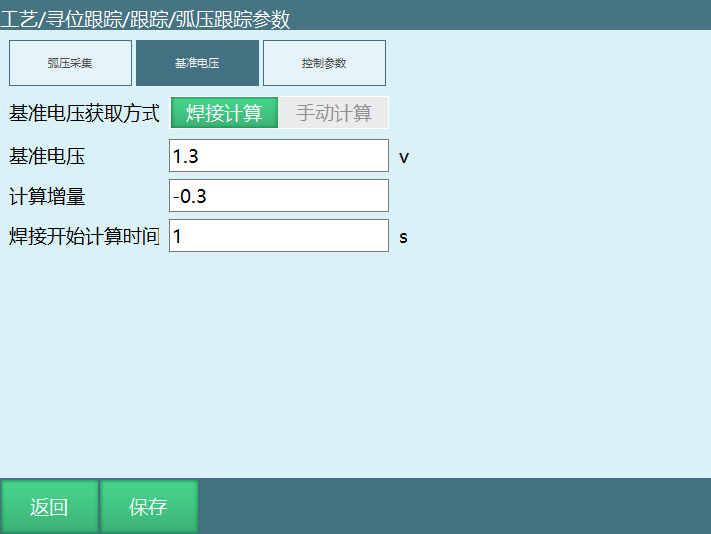
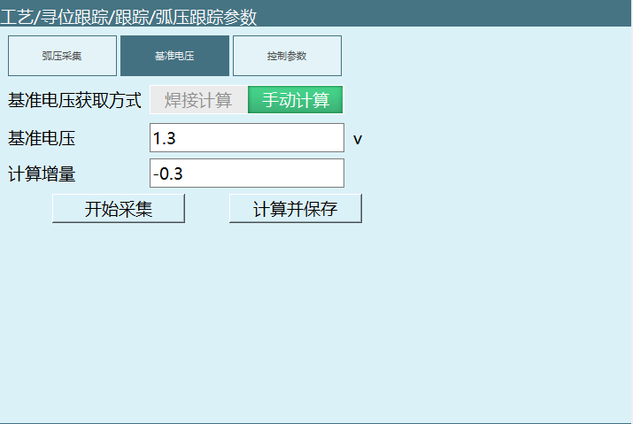
Reference Voltage Acquisition Method: Divided into welding calculation and manual calculation. During welding calculation, after setting voltage and passing the welding start calculation time, the reference voltage is calculated. Manual calculation requires running the complete trajectory.
Reference Voltage: User sets desired voltage. When welder voltage exceeds or is less than this set voltage value, correction is needed.
Calculation Increment: Voltage value that needs compensation. Generally control target value is a few tenths V less than calculated value.
Welding Start Calculation Time: Time needed to calculate reference voltage after welding starts. Only exists in welding calculation.
Start Collection: Only exists in manual calculation. When selecting manual calculation, the arc voltage popup interface will display. When starting to run, click start collection. When running ends, click end collection.
Calculate and Hold: After running ends, click calculate and save. Reference voltage will be saved in controller and displayed on interface.
Note: Reference voltage calculated by welding calculation will not be displayed on the teach pendant, can only be seen in logs.
Control Parameters
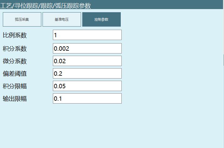
Proportional Coefficient: Proportional response to system deviation. Once deviation occurs, proportional adjustment immediately produces adjustment to reduce deviation. Larger proportional effect speeds up adjustment and reduces error, but too large proportion reduces system stability and may cause system instability.
Integral Coefficient: Eliminates steady-state error and improves astaticism. Because there is error, integral adjustment proceeds until no error, then integral adjustment stops, outputting a constant value. Integral effect strength depends on integral time constant Ti. Smaller Ti means stronger integral effect. Conversely, larger Ti means weaker integral effect. Adding integral adjustment can reduce system stability and slow dynamic response. Integral effect is often combined with other two adjustment laws to form PI or PID regulator.
Derivative Coefficient: Derivative effect reflects the rate of change of system deviation signal, with predictability. Can foresee deviation change trend, thus producing advanced control effect. Before deviation forms, it has been eliminated by derivative adjustment. Therefore, it can improve system dynamic performance. With appropriate derivative time, it can reduce overshoot and adjustment time. Derivative effect amplifies noise interference, so too strong derivative adjustment is not good for system anti-interference. Additionally, derivative reflects rate of change, and when input has no change, derivative effect output is zero. Derivative effect cannot be used alone, needs to be combined with other two adjustment laws to form PD or PID controller.
Deviation Threshold: When controlled quantity deviation is greater than this value, proportional and integral ratios will be reduced. Generally set a large deviation.
Integral Limiting: Prevent error integral from being too large.
Output Limiting: Prevent single adjustment from being too large.
Program