1 IO
1.1 Input/Output Instructions
1.1.1 DIN - IO Input
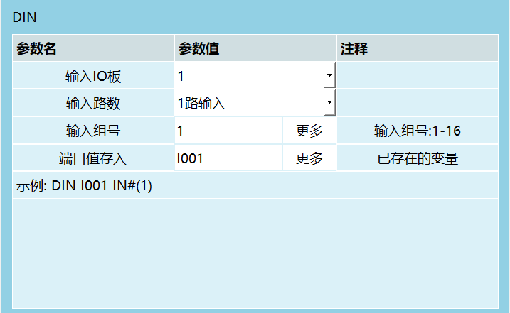
This instruction is used to read digital input status into a variable. The variable can be a local integer variable, global integer variable (INT, GINT) or local boolean variable, global boolean variable (B, GB).
Parameter Description:
| Parameter Name | Parameter Value | Comment |
|---|---|---|
| Input IO Board | 1-way input | 1-way input |
| Input Group Number | More | Input group number: 1-16 |
| Port Value Store To | 1001 | More, existing variable, example: DIN I001 IN#(1) |
Input IO Board: Can select IO board 1-4.
Input Channels:
IN#- 1-way input. 1 channel per group. Groups 1-16 correspond to ports 1-16 respectively.IGH#- 4-way input. Every 4 channels per group. Ports 1-4, 5-8, 9-12, 13-16 are groups 1-4 respectively. Group number can be filled 1-4. For example, to read input status of ports 5-8 simultaneously, fill group number 2.IG#- 8-way input. Every 8 channels per group. Ports 1-8 are group 1, 9-16 are group 2. For example, to read input status of ports 9-16 simultaneously, fill group number 2.
When reading multiple ports simultaneously, port status is converted to decimal and saved to variable. The read group number can be obtained from the corresponding variable.
Example 1: Read ports 5-8, 4 channels simultaneously. Status as follows, saved to I001.
| 1 | 2 | 3 | 4 |
|---|---|---|---|
| 0 | 1 | 1 | 0 |
Binary value is 0110, converted to decimal is 6.
Saved in system as DIN I001 IGH#(1) 6.
Example 2: Read ports 9-16, 8 channels simultaneously. Status as follows, saved to GI001.
| 16 | 15 | 14 | 13 | 12 | 11 | 10 | 9 |
|---|---|---|---|---|---|---|---|
| 0 | 1 | 1 | 0 | 1 | 0 | 0 | 1 |
Binary value is 01101001, converted to decimal is 105.
Saved in system as DIN GI001 IG#(2) 105.
Input Group Number: Can set 1/4/8-way input status simultaneously, or bind variable value.
Port Value Store To: Store the value read from IO input into the selected variable.
1.1.2 DOUT - IO Output
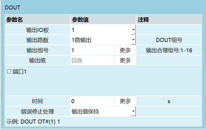
This instruction is used to output digital signals through digital IO board.
Parameter Description:
| Parameter Name | Parameter Value | Comment |
|---|---|---|
| Output IO Board | 1-way output | Output channels |
| DOUT Group Number | 1 | Output group number |
| Output Group Number | More | Valid output group number: 1-16 |
| Output Value | Optional | More, port 1 |
| Time | 0 | More, S |
| Error Stop Handling | Output value hold | Example: DOUT OT#(1)1) |
Output IO Board: Select the IO board for output. Can select 1-4.
Output Channels:
OT#- 1-way output. 1 channel per group. Groups 1-16 correspond to ports 1-16 respectively.OGH#- 4-way output. Every 4 channels per group. Ports 1-4, 5-8, 9-12, 13-16 are groups 1-4 respectively. Group number can be filled 1-4. For example, to output to ports 5-8 simultaneously, fill group number 2.OG#- 8-way output. Every 8 channels per group. Ports 1-8 are group 1, 9-16 are group 2. For example, to output to ports 9-16 simultaneously, fill group number 2.
Output Group Number: Can set 1/4/8-way IO output simultaneously, or bind variable value.
Output Value: Can select self-select or output through variable, or bind variable value.
- If self-select, check each port state in each IO group. Checked means output 1, unchecked means output 0.
- If output through variable, variable value is converted from decimal to binary during output. Specific method same as DIN.
Time: After instruction execution, wait specified time, then invert output.
Error Stop Handling: During IO signal output process, if error alarm occurs, IO signal will handle differently.
- Select output value hold: When program is running, if alarm or other unexpected situation occurs, port output maintains current state, and timing pauses. After clearing alarm error and program resumes normal operation, IO output timing continues from the remaining paused time. When timing ends, port inverts.
- Select timing end stop: Regardless of situation, when port timing ends, port value inverts. Not affected by pause or error.
1.1.3 AIN - Analog Input
This instruction is used to read the input value of a single port on the analog IO board into a variable.
Parameter Description:
- Analog Input Port: Select the input port to read.
- Variable Name: Select the variable name to read into, e.g., GD001.
1.1.4 AOUT - Analog Output
This instruction is used to set the output value of a single port on the analog IO board. Output value can be a floating point number.
Parameter Description:
- Analog Output Port: Select the output port to set value.
- Variable Value Source: Select global floating point GDOUBLE or local floating point DOUBLE variable or manual input value.
1.1.5 PULSEOUT - Pulse Output
This instruction is used to control pulse output of IO boards supporting PWM.
Parameter Description:
- Count: Total number of pulse outputs.
- Frequency: Pulse output frequency. For example, default value 100 means 100 pulses per second.
IO boards supporting this function:
- Huatai IOPWM
- INEXBOT R1PWM
Usage Method:
Modify configuration file controller.json:
"Io": {
    "pulse": {
        "exist": true,
        "type": "UA_PWM"
    }
}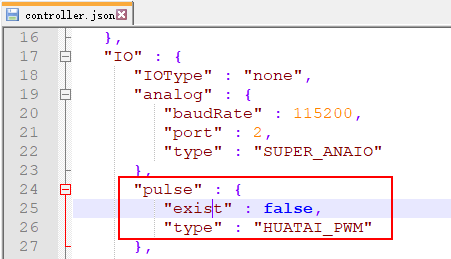
Find parameters under "IO" - "pulse":
- exist parameter, change to true/false
- true: Function available
- false: Function disabled
- type parameter, change to corresponding IO board
- HUATAI_PWM: Huatai IO
- INEXBOT_PWM: INEXBOT R1
1.1.6 READ_DOUT - Read Output
This instruction is used to read the current digital IO board output status into a variable. Usage method is the same as DIN, just reads output status.
2 IO Status Prompt Settings
In the status prompt settings interface, can set corresponding I/O ports and port levels for functions such as startup prompt, robot running status, error prompt, enable, mode status, emergency stop, etc.
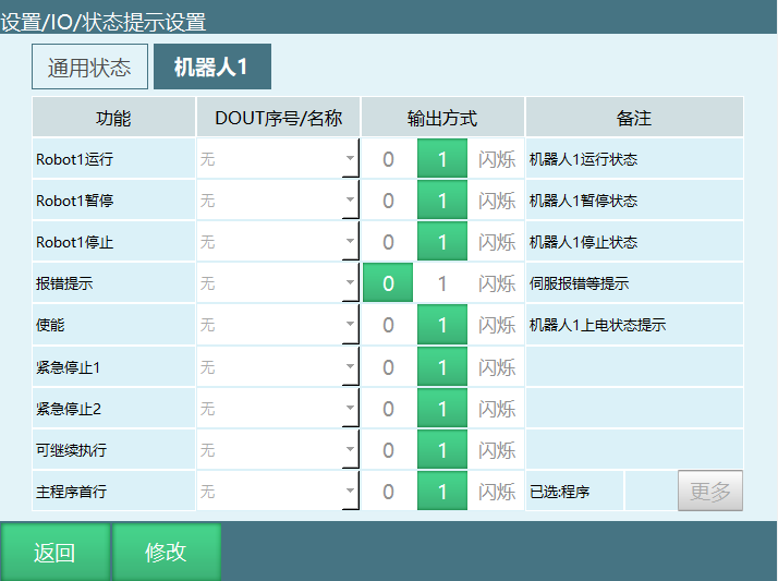
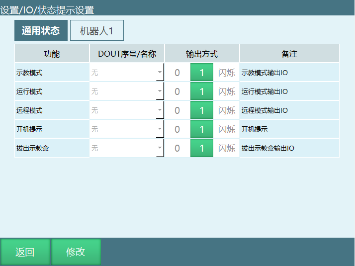
Function Description:
| Function | Description |
|---|---|
| Robot1 Running | When robot 1 is running, corresponding port outputs high/low level |
| Robot1 Paused | When robot 1 is paused, corresponding port outputs high/low level |
| Robot1 Stopped | When robot 1 is stopped, corresponding port outputs high/low level |
| Error Prompt | When robot servo error occurs, corresponding port outputs high/low level. Can set constant or blinking |
| Enable | When robot is powered on, corresponding port outputs high/low level |
| Emergency Stop 1 | After emergency stop signal triggers, corresponding port outputs high/low level. Can be set by user |
| Emergency Stop 2 | After emergency stop signal triggers, corresponding port outputs high/low level. Can be set by user |
| Main Program First Line | Corresponding port outputs a high level signal with parameter 1. Program cursor jumps to main program first line |
| Can Continue | Corresponding port outputs a high level signal with parameter 1. Can run paused program |
| Startup Prompt | Controller startup output status. Startup outputs high level |
| Teach Mode | When in teach mode, corresponding port outputs high/low level |
| Run Mode | When in run mode, corresponding port outputs high/low level |
| Remote Mode | When in remote mode, corresponding port outputs high/low level |
| Remove Teach Pendant | After removing teach pendant, corresponding port outputs high/low level. Can be set by user |
3 IO Safety Settings
In the safety settings interface, can set corresponding I/O ports and port levels for functions such as emergency stop, safety curtain, etc.
Note: After IO emergency stop is released, need to click clear error button first to clear error before other operations.
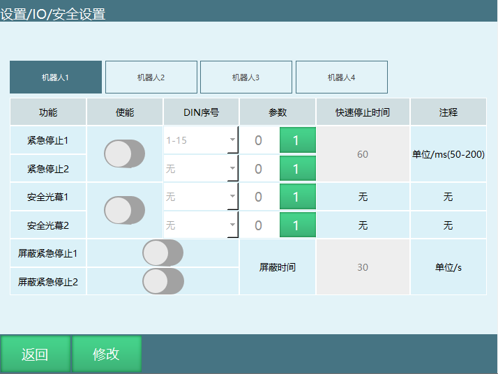
Function Description:
| Function | Description |
|---|---|
| Emergency Stop | After triggering emergency stop signal, robot powers off and switches to servo stop |
| Safety Curtain | Triggering safety curtain pauses robot. Press start button again to continue running |
| Mask Emergency Stop | After turning on, emergency stop signal is masked during mask time |
3.1 IO Reset
When program execution stops or reports error, IO reset function can restore IO output ports to initial state. IO reset is divided into three types: IO reset, mode switch stop, program error stop.
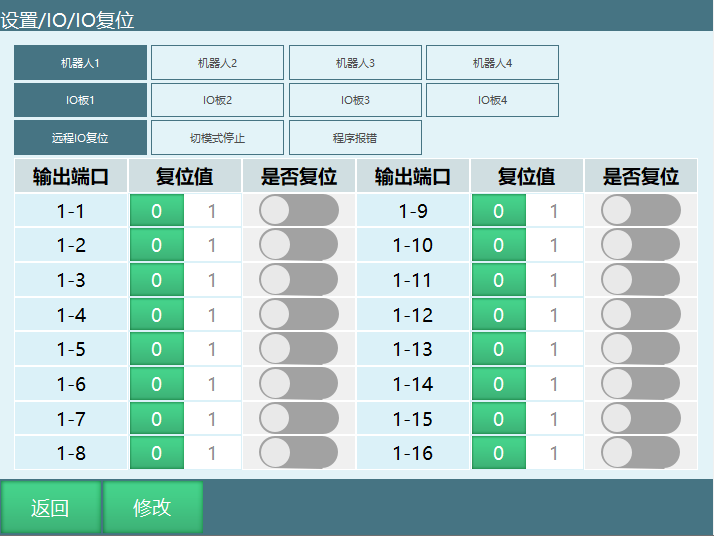
Reset Type Description:
| Reset Type | Description |
|---|---|
| Remote IO Reset | In remote mode, when reset signal is given and robot executes reset program to return to reset point, will reset the IO port set in this interface to reset value. If reset program stops midway, IO reset will not be performed |
| Mode Switch Stop | When running program, switching mode to teach or remote mode causing program to stop, will reset the IO port set in this interface to reset value |
| Program Error Stop | Program error causing program to stop, will reset the IO port set in this interface to reset value. Specific error types: servo error, IO setting error, system runtime error |
Usage Steps:
- Enter IO reset interface
- Select robot
- Click to enter reset scenario (IO reset, mode switch stop, program error stop)
- Select IO board
- Turn on the "Whether to Reset" switch corresponding to the IO port that needs to be reset
- Select reset value (0/1). 0 is low level, 1 is high level.
3.2 IO Configuration
The system automatically identifies IO model based on hardware connection order. No setting needed. Can be used to view IO board count and model.
Enter [Settings] - [IO] - [IO Configuration].
At this time, the input box is grayed out and cannot input values.
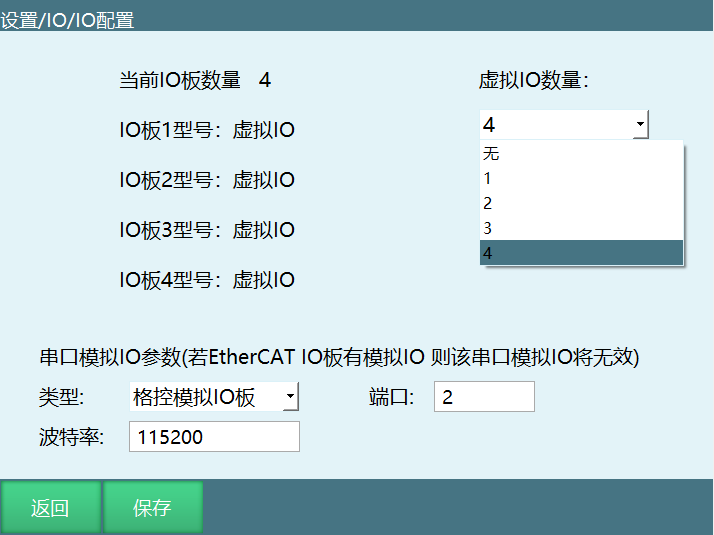
After clicking modify, the modify button changes to save. Virtual IO board count dropdown selects the needed virtual IO.
Note: Virtual IO is for program debugging and demonstration only. No actual IO signals are connected.
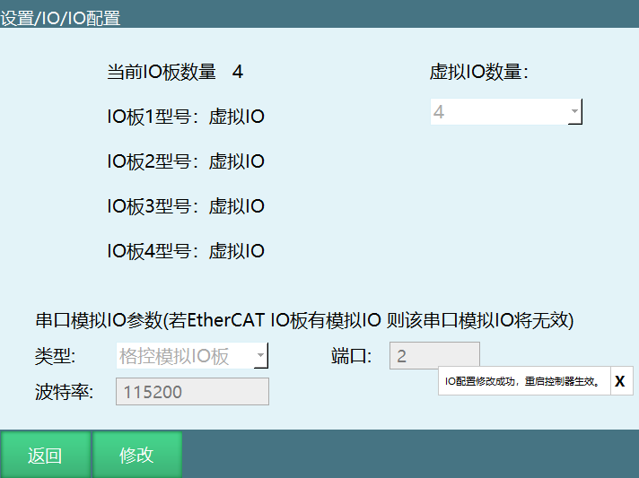
Click save. Restart to take effect. Modification successful.
3.3 Enable IO
If using hardwired enable teach pendant, after connecting cables, select the corresponding DIN port on this page and turn on enable switch. Power-on enable function is controlled by IO board input signal. Do not set for non-hardwired enable teach pendant.
After turning on this function, teach pendant enable button becomes invalid and cannot be used.
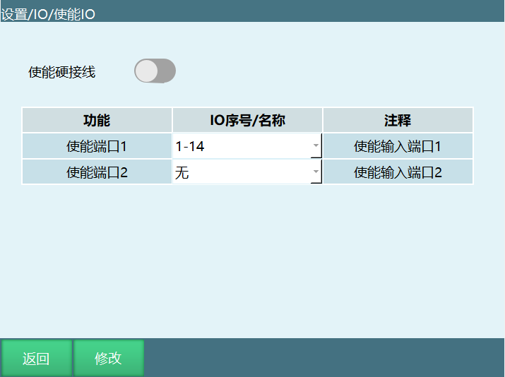
Enable port 1 is power-on enable. Enable port 2 is power-off enable. Power-on only requires turning on enable port 1. In any case, as long as enable port 2 is turned on, power-off will occur.
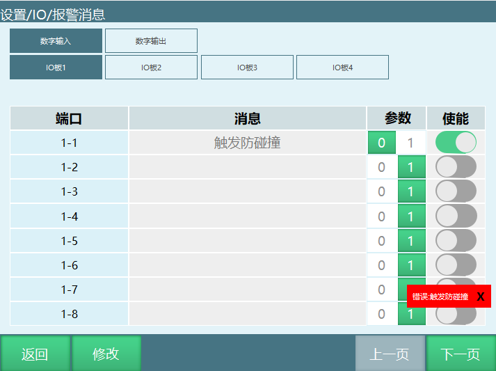
3.4 Alarm Message
This function can customize IO input/output port alarm content. Alarm message priority is higher than other types of IO alarm information.
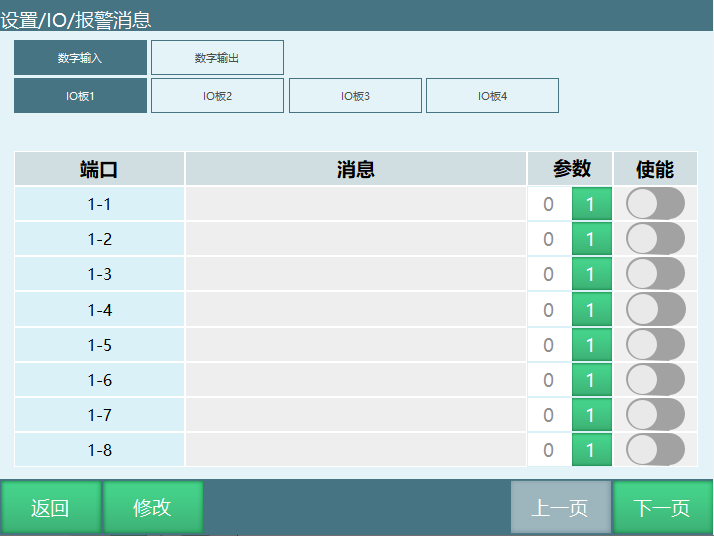
Usage Example:
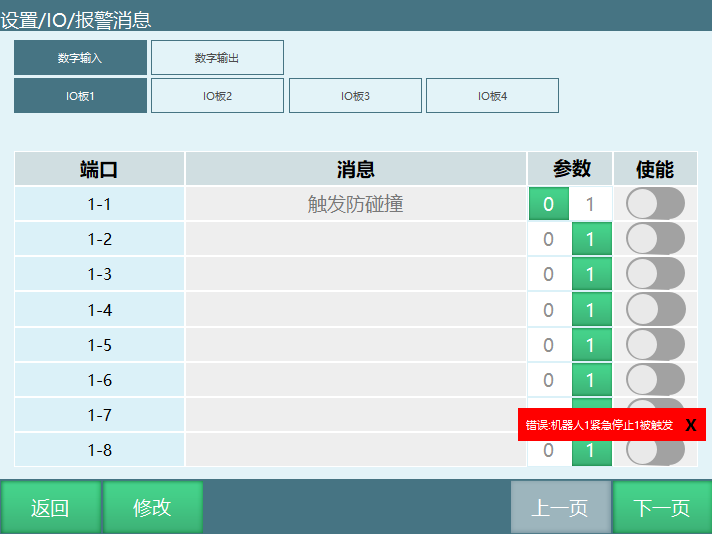
Set IO emergency stop signal port 15 for anti-collision IO. 1 triggers, 0 releases. When DIN1 is triggered, will report "Robot 1 IO Emergency Stop Triggered". At this time, find DIN1 in alarm message interface, enter "Anti-collision Triggered" in message column. When DIN15 is triggered again, error will show "Anti-collision Triggered" instead of "Robot 1 IO Emergency Stop Triggered".
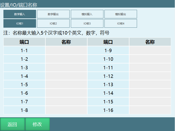
3.5 Port Name
Port name supports maximum input of 5 Chinese characters or 10 English characters. After successful setting, the name will be automatically displayed when using IO port related dropdown options.
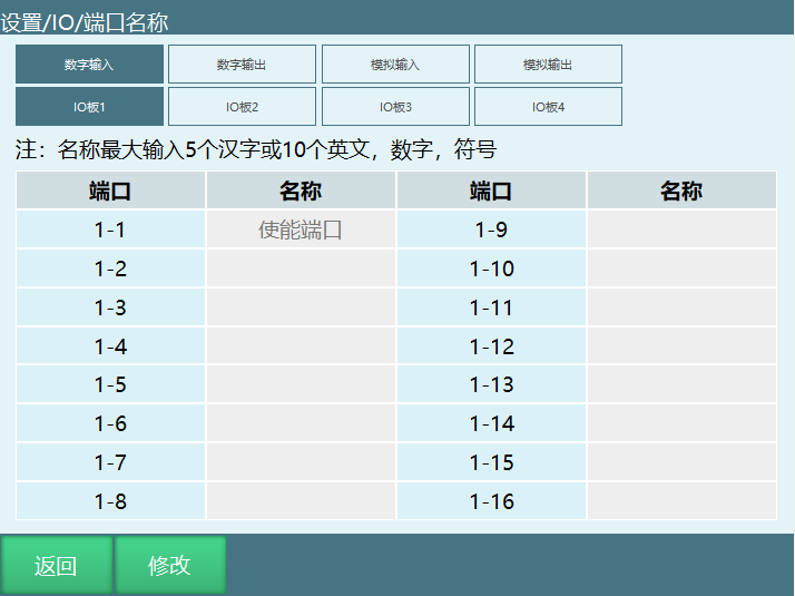
Usage Example:
If DIN1-1 name is set to "Enable Port", then in [Status] [Input/Output], DIN1 will display name "Enable Port".
4 Remote Mode IO Reservation Brief Description
Signal Description Table
Digital IO Input
| Function | Supported Mode | Trigger/Output Method | Description |
|---|---|---|---|
| Start | Remote Mode | Rising Edge | When parameter is 1, effective when signal changes 0→1 |
| Stop | Remote Mode | Continuously Effective | When parameter is 1, signal is continuously effective |
| Pause | Remote Mode | Continuously Effective | When parameter is 1, signal is continuously effective |
| Clear Alarm | Remote Mode | Rising Edge | When parameter is 1, effective when signal changes 0→1 |
| Reserve and Start | Remote Mode | None | When on, powers on immediately after successful reservation |
| IO Remote Program 1-10 | Remote Mode | Pulse (period 0.6s) | When parameter is 1, effective when signal 0-1-0. Program reservation requires trigger for at least 0.6 seconds |
| Emergency Stop 1 | Teach, Run, Remote | High Level | Scans once per millisecond, triggers upon detection |
| Emergency Stop 2 | Teach, Run, Remote | High Level | - |
| Safety Curtain 1 | Run (during), Remote (during) | High Level | - |
| Safety Curtain 2 | Run (during), Remote (during) | High Level | - |
| Mask Emergency Stop 1 | Used with emergency stop | - | Button on masks emergency stop function. After set time, re-check emergency stop signal |
| Mask Emergency Stop 2 | Used with emergency stop | - | - |
Digital IO Output
| Function | Supported Mode | Trigger/Output Method | Description |
|---|---|---|---|
| Startup Prompt | No mode limit | Constant, Blink, only outputs at startup | Outputs high level |
| Robot1 Running | Teach, Run, Remote Mode | Constant, Blink | Outputs high level when program is running |
| Robot1 Paused | Teach, Run, Remote Mode | Constant, Blink | Outputs high level when program is paused |
| Robot1 Stopped | Teach, Run, Remote Mode | Constant, Blink | Outputs high level when program is stopped |
| Error Prompt | No mode limit | Constant, Blink | Constant outputs high level, Blink outputs pulse (period 1s, 0.5s on, 0.5s off) |
| Enable | No mode limit | Constant, Blink | Outputs high level |
| IO Remote Program 1-10 Reservation Output | Remote Mode | Constant, Blink | Not reserved/reserved: not lit; Reserving: blink, period 1.2s, 0.6s on, 0.6s off; Running: constant, outputs high level |
| Emergency Stop 1 | When signal triggers | High Level, Low Level, Blink | When parameter is 1, outputs high level |
| Emergency Stop 2 | When signal triggers | - | - |
| Remove Teach Pendant | No mode limit | High Level, Low Level, Blink | Click remove teach pendant, outputs 1 or 0 |
| Can Continue | When signal triggers | High Level, Low Level, Blink | Outputs a high level signal with parameter 1, can run paused program |
| Main Program First Line | Teach, Run, Remote Mode | High Level, Low Level, Blink | Outputs a high level signal with parameter 1, program cursor jumps to main program first line |
Note: This description uses output 1 as high level output as example.
4.1 Remote Mode Status Description
Status Classification:
- Not Reserved: After entering remote mode, no programs have been reserved, or reservations have been cancelled. Displays Not Reserved.
- Reserving: Reservation successful displays Reserving.
- Running: Program is running displays Running.
- Reserved: Program completed or program was triggered to stop displays Reserved.
Note: Remote mode cannot modify speed. Speed modification needs to be done in advance in [Settings - Remote Program Settings].
Reserve Program:
- Trigger corresponding program's IO port to successfully reserve program. To cancel, trigger the program's corresponding IO port again.
- Start by directly triggering the corresponding IO port.
- Reserve and Start: Signal 0-1 (press button) for more than 0.6 seconds, then 1-0 (release button), program runs directly. When Reserve and Start is on, start signal is not needed.
- Reserved program can be re-reserved after running.
Troubleshooting: After IO function setting is successful, go to Status - IO Function Status to check if setting is successful or if there are conflicting functions.
Reset Point Setting: Reset point function supports joint and linear movement to safety point, or use reset program instruction to customize reset trajectory and position.
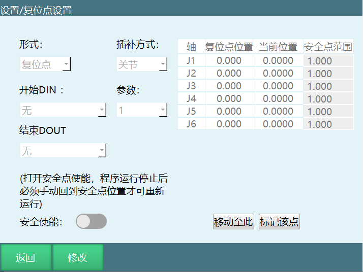
Parameter Description:
| Parameter | Description |
|---|---|
| Form | Reset Point, Reset Program |
| Interpolation Method | Joint, Linear. Joint interpolation speed is 10% of global speed. Linear interpolation speed is 100mm/s. Reset program speed equals instruction speed x status bar speed |
| Safety Enable | After turning on, program execution will check if robot is at reset point (safety point). Must be at reset point to continue program |
| Start DIN | Reset point trigger signal |
| Parameter | Reset point trigger signal 0 effective or 1 effective |
| End DOUT | Status signal output after returning to reset point |
| Safety Point Range | Safety range error for each axis. Within range is judged to be at reset point (safety point) |
| Mark This Point | Set current robot coordinates as reset point. After clicking confirm, setting is successful |
| Move to This | Move to reset point via joint interpolation |
4.2 Remote Mode Control Description
When the control system has teach pendant, touch screen, and I/O control device simultaneously, control priority is: Teach Pendant > Touch Screen > I/O Control Device.
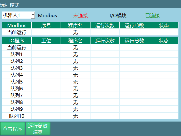
After switching to remote mode, control switches to touch screen. If no touch screen, switches to I/O control. At this time, teach pendant interface only displays Modbus module and I/O module connection status and I/O program.
When both touch screen and I/O module are present, set I/O module enable in the touch screen.
4.3 Remote IO Control
4.3.1 Remote IO Function Selection Settings
In "Remote Program Settings - Remote IO Function", can set corresponding I/O ports and port levels for remote IO control functions such as start, stop, pause, emergency stop, clear alarm, etc. Can set the program run by I/O module remote control.
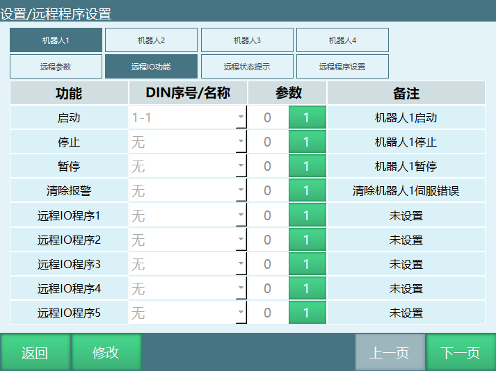
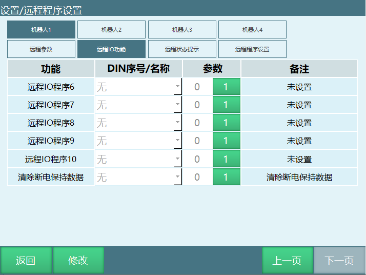
Function Description:
- Programs set in I/O module can only select programs already set in "Remote Program Settings" interface.
- Remote reservation programs support up to 10.
- Reserve and Start: After turning on, the first reserved program will immediately power on and run after successful reservation. Can reserve other programs at this time.
4.3.2 Remote Program Settings
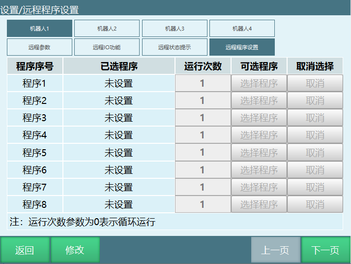
Function Description:
- Remote program settings interface can set programs used by touch screen and I/O control module.
- If multiple robots, can select the robot to set at the robot position and set each program for that robot.
- Programs used by I/O control module need to be set in IO function interface.
- Selected programs in remote program interface can be cancelled by clicking cancel button.
- Fill corresponding number for run count. 0 means loop run.
4.3.3 Reservation Mode
In "Settings/Operation Parameters":
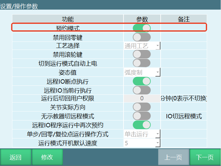
Function Description:
- After turning on reservation mode enable: Trigger remote IO program signal, program reservation successful, trigger start signal, robot runs.
- After turning off reservation mode enable: Trigger remote IO program signal, robot runs directly and triggering other remote IO program signals is invalid at this time. After robot finishes running, can re-trigger remote IO program signal. No start signal needed.
5 Remote Function Usage
5.1 Remote Function Overview
Set 10 remote programs and run count for each program. Before running, queue the 10 programs. During running, follow queue order and run count. After queue completes, stop and wait for re-queuing.
Remote Function Usage Steps: Write Program → Set Remote Program → Set IO → Switch to Remote Mode → Reserve Queue → Run
1. Write Program
Create new program and insert instructions. Ensure program can run normally.
2. Set Remote Program
Enter "Settings - Remote Program Settings" interface. Set program 1-10's program name and run count. If want a single program to loop infinitely, set that program's run count to 0.
Note:
- Program name here points to programs in "Project" interface. After modifying instructions inside program, remote program will automatically follow modification. No need to re-set remote program.
- If program name is modified, please re-set that program in remote program settings interface.
3. Set IO
In "IO - IO Function" interface, set each function's corresponding IO port and effective value. When effective value is 1, high level is effective. When effective value is 0, low level is effective.
Note: The IO port function corresponding to program 1-10 does not mean selecting that program to run, but queuing that program in remote mode.
4. Switch to Remote Mode
Rotate mode selection key to remote mode position or click mode status in program and select remote mode.
Note:
- When teach pendant is not connected to controller, starting controller automatically enters remote mode.
- When controller connects IO, Modbus device, and teach pendant simultaneously, priority is teach pendant > Modbus device > IO device. After switching to remote mode, Modbus device is effective, IO device is invalid. At this time, turning off enable button in Modbus device makes IO effective.
5. Reserve Queue
Example:
IO function settings are:
- Run - Port 1, effective value 1
- Stop - Port 2, effective value 1
- Pause - Port 3, effective value 1
- Clear Error - Port 4, effective value 1
- Program 1 - Port 5, effective value 1
- Program 2 - Port 6, effective value 1
- Program 3 - Port 7, effective value 1
- Program 4 - Port 8, effective value 1
- Program 5 - Port 9, effective value 1
- Program 6 - Port 10, effective value 1
- Program 7 - Port 11, effective value 1
- Program 8 - Port 12, effective value 1
- Program 9 - Port 13, effective value 1
- Program 10 - Port 14, effective value 1
Queuing method: Give port 6 a high level for 1 second then release, program 2 queues first. Give port 8 a high level for 1 second then release, program 4 queues second. And so on.
Note:
- To cancel a program from the queue, give the corresponding IO port a 1 second high level again. The program will be cancelled from the queue.
- Queue can only have 10 programs. Same program cannot be queued repeatedly.
- When a program is running, can re-add that program to the end of the queue.
6. Run
Give the port with run function a high level, and robot starts running according to queue order and run count. After completion, servo does not power off. At this time, re-add program to queue and robot will immediately run that program.
When queue has no programs but run is triggered, robot powers on but does not move. At this time, queue a program and robot will immediately execute that program.
View Running Status
To view program running details in remote IO control, click the "View Program" button in remote mode interface. Modbus can also use this function to view.
Reset Total Runs
Clear the total run count of currently running program. Can only clear total runs, cannot clear run count.
6 MODBUS
6.1 Modbus Instructions
Open Modbus Connection
This instruction is used to open Modbus communication connection in run mode. Craft number binding is Modbus master craft number.
Disconnect Modbus Connection
This instruction is used to disconnect Modbus communication connection in run mode. Craft number binding is Modbus master craft number.
Get Modbus Connection Status
This instruction stores Modbus connection status in a bool variable. Get connection status by obtaining variable value. This instruction gets status once each time it runs. Usually placed below "Open Modbus Connection".
Modbus Read Operation
This instruction is used to read address codes at corresponding positions in Modbus. Can set address types: 3x, 4x-bit, 3x-bit, 0x.
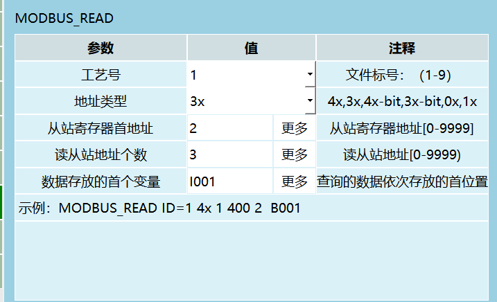
Parameter Description:
| Parameter | Value | Comment |
|---|---|---|
| Craft Number | 1 | File label: (1-9) |
| Address Type | 3x | 4x, 3x, 4x-bit, 3x-bit, 0x, 1x |
| Slave Register Start Address | - | More, slave register address [0-9999] |
| Read Slave Address Count | - | More, read slave address [0-9999) |
| First Variable for Data Storage | 1001 | More, queried data stored sequentially starting from this position. Example: MODBUS_READ ID=1 4x1 4002 B001) |
Usage Example:
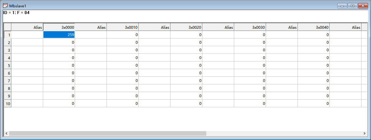
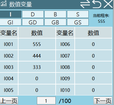
Address code 2 stores value 555. Instruction reads from the first address for the input read address count, stores sequentially into input variables. That is, reads 3 address codes starting from address 2 and stores into I001, I002, I003 respectively.
4x Address Type
4x reads the value stored in the 4x address code selected in the modbus slave. Same as 3x.
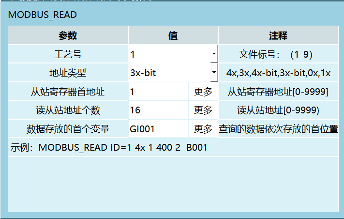
3x-bit Address Type
3x-bit reads any bit status of the value stored in the selected address.
Parameter Description:
| Parameter | Value | Comment |
|---|---|---|
| Craft Number | 1 | File label: (1-9) |
| Address Type | 3x-bit | 4x, 3x, 4x-bit, 3x-bit, 0x, 1x |
| Slave Register Start Address | 1 | More, slave register address [0-9999] |
| Read Slave Address Count | 16 | More, read slave address [0-9999) |
| First Variable for Data Storage | GI001 | More, queried data stored sequentially starting from this position. Example: MODBUS_READ ID=1 4x14002 B001) |
Usage Example:
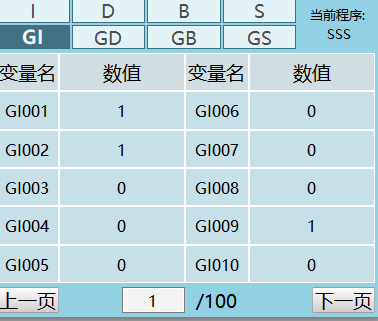
Address code 1 stores value 259. Converted to 16-bit original code is 0000 0001 0000 0011. Read instruction starts from specified variable and stores each bit of original code sequentially from back to front into variables.
That is, convert 259 to binary and store each number from right to left into GI001, GI002, GI003...
Note: Bit 16 (16th variable) is sign bit. 0 means positive, 1 means negative.
4x-bit Address Type
4x-bit reads any bit status of the value stored in the selected address. Same as 3x-bit.
Modbus Write Operation
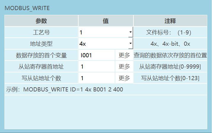
This instruction is used to write variables into address codes at corresponding positions in slave register through modbus. Can set address types: 4x, 4x-bit, 0x. Compared to read, missing 3x, 3x-bit.
Parameter Description:
| Parameter | Comment |
|---|---|
| Craft Number | File label: (1-9) |
| Address Type | 4x, 4x-bit, 0x |
| First Variable for Data Storage | More, queried data stored sequentially starting from this position |
| Slave Register Start Address | Slave register address (0-9999] |
| Write Slave Address Count | Write slave address count [0-123] |
| Example | MODBUS WRITE ID=1 4x B001 2 400) |
4x Address Type
4x writes the value in variables into address codes.
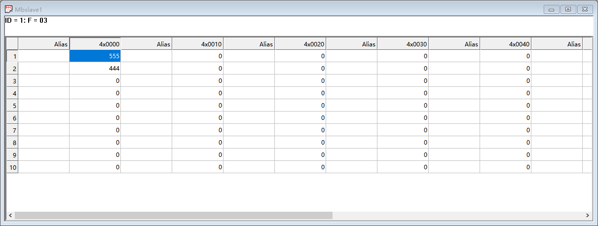
Usage Example:
I001=555, I002=444. Instruction writes the values in variables for the write slave address count into the input start address codes in order.
4x-bit Address Type
4x-bit writes variables composed into 16-bit binary code into address codes.
Usage Example:
I001=1, I002=1, I003=0, I004=1. First variable is I001, register first address is 1, write slave address count is 4.
(Convert to binary original code and fill variables from right to left. Example: 1011 is composed of I004, I003, I002, I001)
That is, compose 4 variables' values into binary code 1011 and store in address 1. Modbus displays decimal number 11.
Note: Bit 16 (16th variable) is sign bit. 0 means positive, 1 means negative. Variable value only judges 0 or 1. Has value is 1, not assigned defaults to 0.
6.2 Modbus Slave
As slave, can set heartbeat detection to confirm communication status with master, and whether to stop when communication disconnects. Protocol can select RTU and TCP, and corresponding port settings.
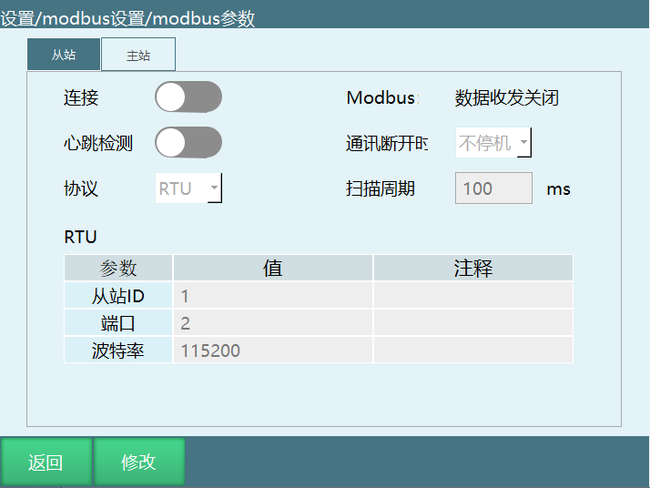
Parameter Description:
| Parameter | Description |
|---|---|
| Heartbeat Detection | After turning on, system will judge communication status with modbus. Turning off will not monitor communication connection with modbus. Generally used for RTU protocol |
| Communication Disconnect | Stop means robot powers off when modbus communication disconnects. Otherwise, no stop, robot does not power off when modbus communication disconnects |
| Protocol | RTU or TCP |
| Scan Period | Frequency at which system scans data within modbus range |
6.3 Modbus Master
As master, can only select communication method and corresponding port settings.
Start address can set whether start address begins from 0 or 1.
When master protocol is set to RTU, need to set check bit, data bit, stop bit.
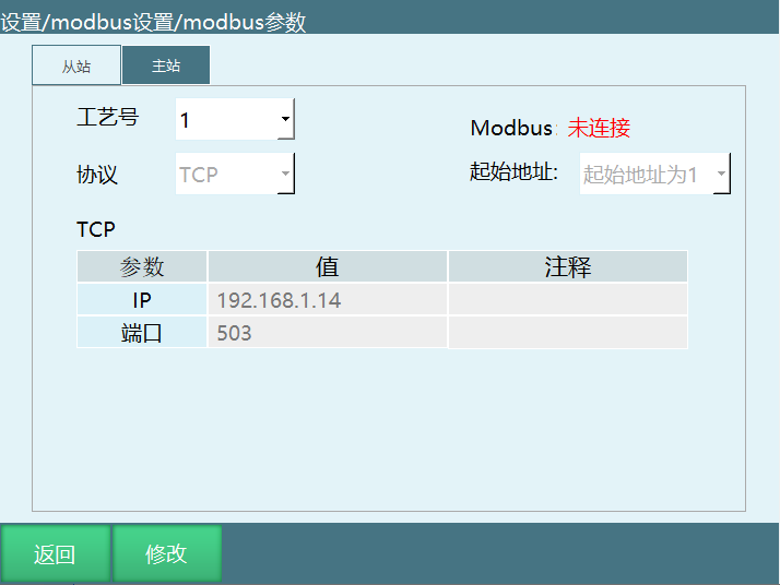
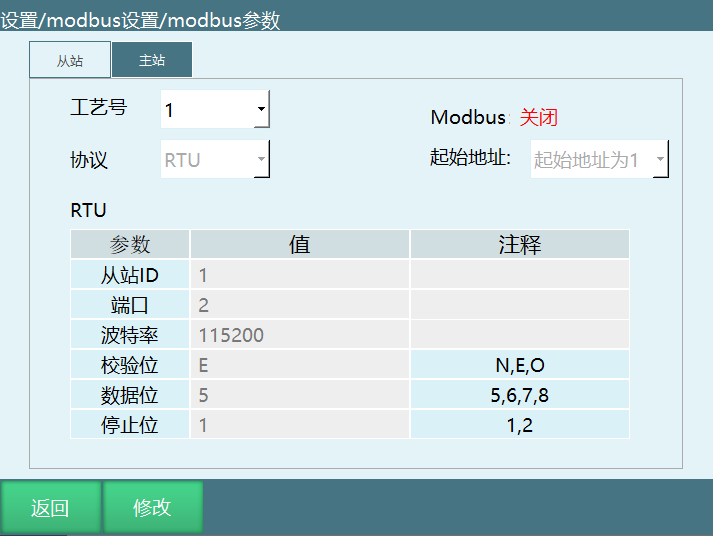
6.4 Modbus Modify Address Code
Step Description
Insert USB drive, export controller configuration.
Find configuration file modbusAddr.json, in the configuration file configFile+date folder.
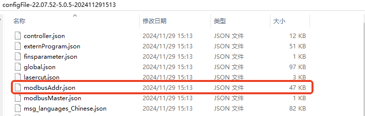
- Open with Notepad++ or other text editor.
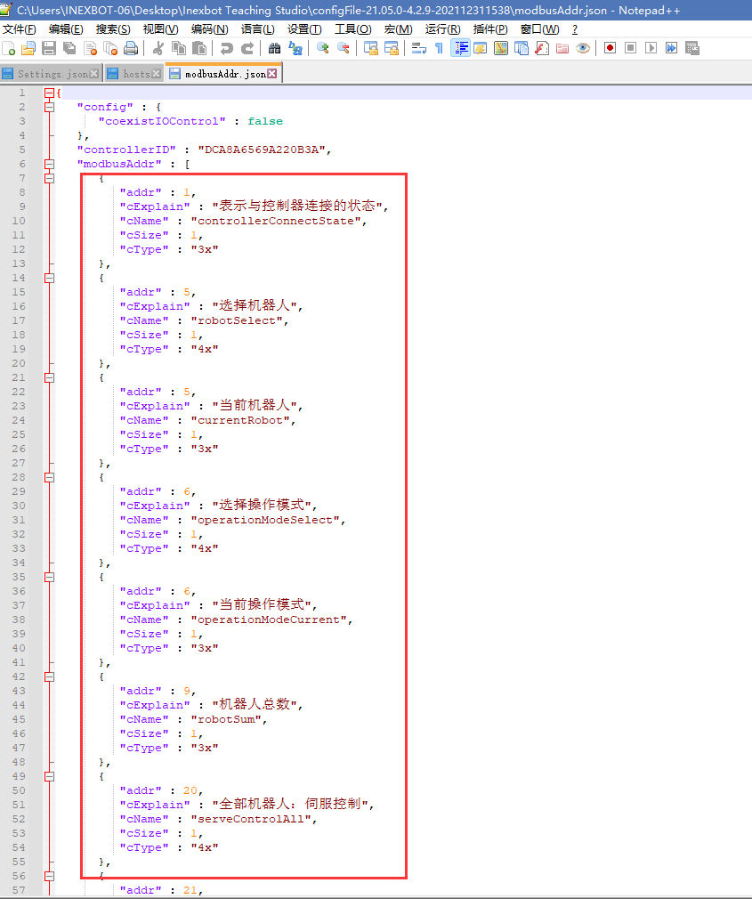
- After opening, can see a set of address code parameters contained in { } (system will automatically generate an original address code).
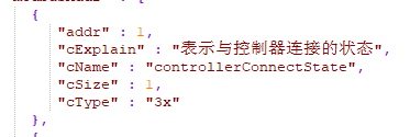
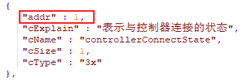
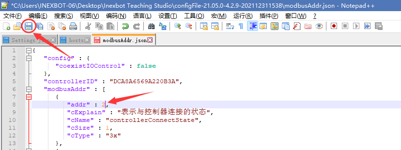
- Modify address by directly changing the number after addr. When number is 0, that address code function is invalid.
- After modification, click save.
- Then re-import this parameter into controller. Restart to take effect.
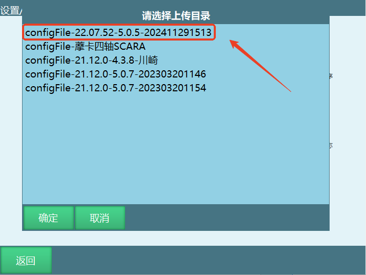
- After modifying parameters, restart or re-open connection to take effect (Import configuration file will automatically restart).
6.5 Modbus Usage
Function Overview
Modbus function can replace some teach pendant functions, remotely control robot running, teaching, view status, etc.
Modbus supports modbusTCP and modbusRTU protocols.
Modbus has teaching and running two modes. Address codes can be found in "MODBUS Address Code List.xls".
6.5.1 Modbus Poll Connection Method
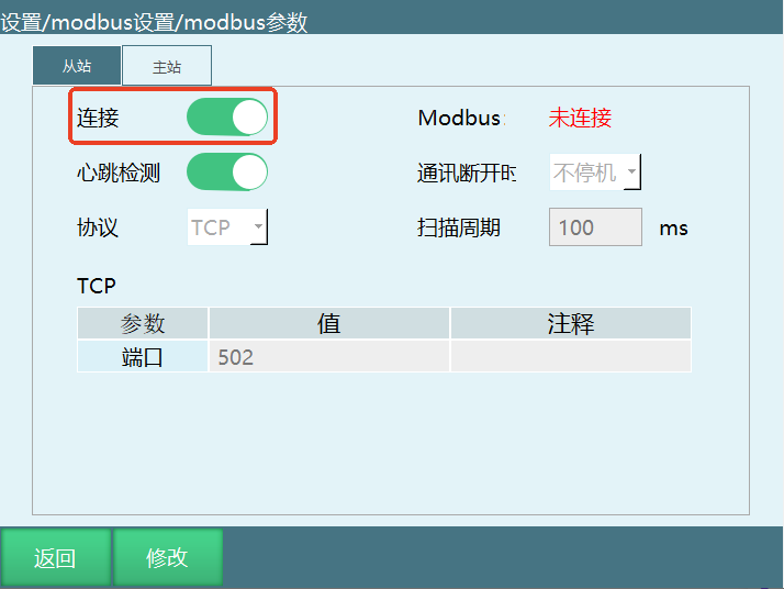
- Open Settings/Modbus Settings/Modbus Parameters, turn on connection switch.
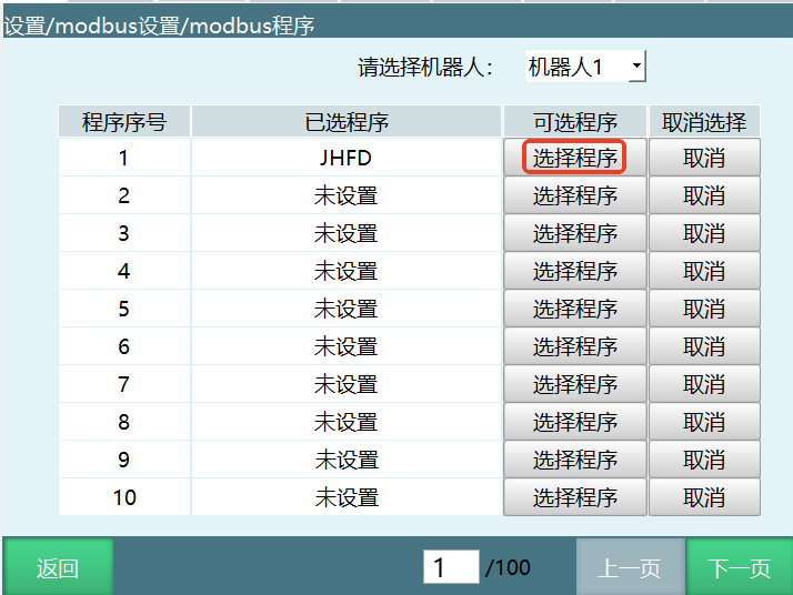
- In Settings/Modbus Settings/Modbus Program interface, select program.
Open ModbusPoll software.
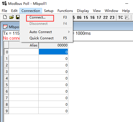
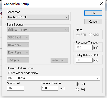
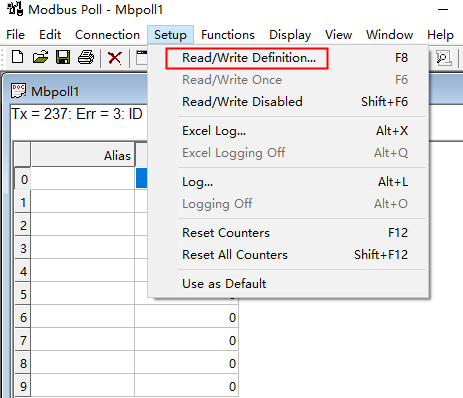
After opening software, need to connect and set up Connection → Connection Setup. Set needed parameters (image parameters are for example only). After clicking OK button, teach pendant page shows connected. If showing connected and disconnected flashing screen, need to change Scan Rate parameter from 1000ms to 100ms in Setup → Read/Write Definition.
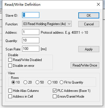
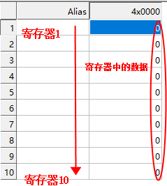
- Set Setup → Read/Write Definition parameters (image parameters are for example only): If address code doesn't take effect, troubleshoot: Change start address to 1, check PLC Addresses option, click OK.
- Double-click register data, fill in related address codes.
6.5.2 Modbus Can Read Global Position in Any Mode
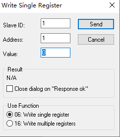
- According to Modbus address 2004, select the global type to read. 0 is GP point, 1 is GE point.
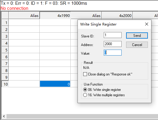
- According to Modbus address 2000, select the global point number to read. Number is 1-999.
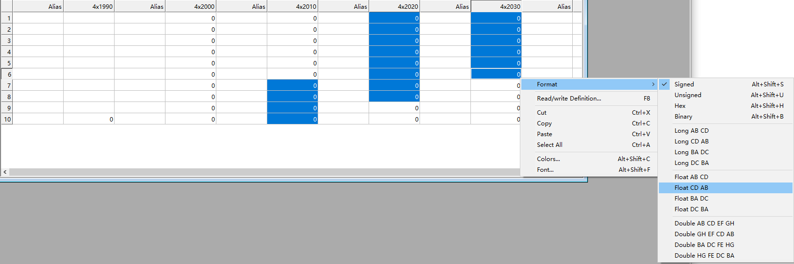
- Change Format of 2017-2028 and 2031-2036 to FloatCD AB.
6.5.3 Modbus Multi-Master Connection
Connect computer and one or more touch panels to controller through switch.
Controller as slave, Modbus poll and touch panel as master. Modbus poll can open multiple as multiple masters. Currently supports up to 9 masters simultaneously.
Modbus poll click connection, select connect. Connection type select TCP. IP address and port number consistent with teach pendant. Scan period consistent with teach pendant.
Modbus Poll and touch panel can control robot simultaneously.
6.5.4 Modbus and IO Priority
Enter teach pendant through display, find ModbusAddr.json in robot/config/ directory.
Open ModbusAddr.json through vi editor.
{
  "coexistIOControl": false,
  "modbusPriorityHigh": false,
  ...
}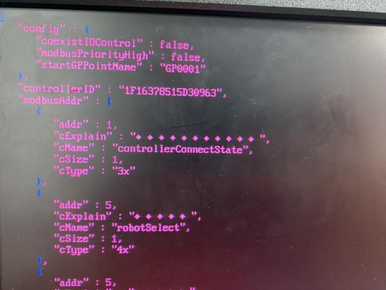
coexistIOControl:
falsemeans Modbus and IO not shared. When Modbus is connected, IO cannot control robot.truemeans Modbus and IO shared. Modbus and IO can control robot simultaneously.
Note: When Modbus and IO are shared, job files called are from [Remote Program Settings]. Also [Operation Parameters - Reservation Mode] must be turned on.
When coexistIOControl: false, modbusPriorityHigh has no effect regardless of false or true. Modbus default priority is higher and when Modbus is connected, IO cannot control.
When coexistIOControl: true:
modbusPriorityHigh: falsemeans Modbus and IO shared with IO priority higher. Modbus and IO can control robot simultaneously and Modbus runs according to IO settings (teach pendant settings), e.g., breakpoint and current line execution.modbusPriorityHigh: truemeans Modbus and IO shared with Modbus priority higher. Modbus and IO can control robot simultaneously but each runs according to its own settings. For example, teach pendant sets breakpoint execution off, Modbus address code 19 input 0 stop then input 3 breakpoint start will breakpoint run, but IO control cannot breakpoint run.
6.5.5 Modbus Touch Screen Usage Process
This section uses Weintek touch screen and ModbusTCP protocol as example. Touch screen model is MT6071iP.
Usage Steps: Write Program → Set Modbus Program → Set Modbus Parameters → Switch to Remote Mode → Touch Screen Prepare → Select Program → Run
(1) Write Program
Use teach pendant to write program. Ensure it can run normally.
(2) Set Modbus Program
In "Settings - Modbus Settings - Modbus Program", set programs. After successful setting, selected program list will display program name. Can set up to 1000 programs.
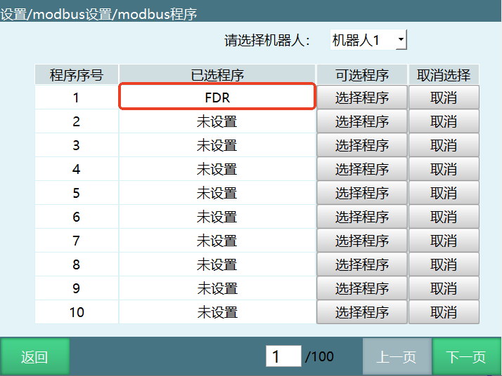
(3) Set Modbus Parameters
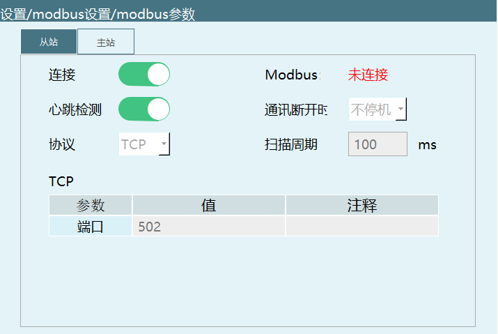
In "Settings - Modbus Settings - Modbus Parameters", set protocol to TCP, controller as master/slave set to slave, IP not modified, port set to 502, turn on connection enable. Restart controller to take effect.
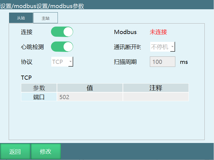
(4) Switch to Remote Mode
Rotate mode selection key to remote mode position or click mode status in program and select remote mode.
Note: When controller connects IO, Modbus device, and teach pendant simultaneously, priority is teach pendant > Modbus device > IO device. After switching to remote mode, Modbus device is effective, IO device is invalid. At this time, turning off enable button in Modbus device makes IO effective.
(5) Touch Screen Preparation
Connect touch screen RJ45 network port, teach pendant network port, controller "Teach Pendant" network port to the same switch.
Touch screen connects to controller IP: 192.168.1.13, port: 502.
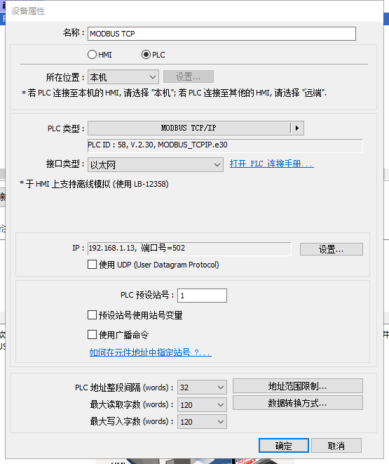
After touch screen program is edited and run, teach pendant remote interface shows modbus changed from not connected to connected.
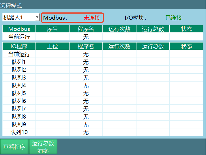
(6) Select Program
Use touch screen to write 1 to 4x type address code 45. Robot 1 selects demo program 1.
Use touch screen to write 5 to 4x type address code 61. Robot 1 sets run count to 5 (not effective). Use touch screen to write 1 to 4x type address code 71. Confirm modify run count (run count 5 becomes effective).
(7) Run
Use touch screen to write 1 to 4x type address code 29. Switch to servo ready.
Use touch screen to write 1 to 4x type address code 19. Run job file.
6.5.6 Modbus Parameter Description
Connection
After Modbus setting is complete, need to turn on connection button. Right side can view connection status.
Heartbeat Detection
After turning on, used to detect send/receive frequency between Modbus and controller. After disconnecting Modbus connection, heartbeat detection shows data send/receive off.
Protocol
Divided into TCP protocol and RTU protocol.
Master/Slave
Master, Slave.
TCP Parameters
| Parameter | Description |
|---|---|
| IP | Modbus device IP address. Only effective when set to master |
| Port | Modbus device port |
RTU Parameters
| Parameter | Description |
|---|---|
| Slave ID | Default is 1 |
| Port | Controller serial port number |
| Baud Rate | Fill touch screen's corresponding baud rate |
Q&A
Q1: In IO control and remote mode, why can't program run after reservation?
- Confirm if the program's corresponding port in remote IO function settings is correctly bound and effective value is set correctly.
- Check if remote mode has been switched successfully, and if Modbus device priority is higher than IO device.
- If using Reserve and Start, ensure "Reservation Mode Enable" is turned on. Otherwise need to queue first then trigger start signal.
Q2: What are common reasons for Modbus read/write operation failure?
- Check if Modbus protocol type (RTU/TCP) matches slave configuration.
- Confirm target address code start value, count, and read/write type are correct. Especially the distinction between 3x, 4x, 0x and bit types.
- If using ModbusPoll, check if start address is 0 or 1, and ensure Scan Rate is set reasonably.
Q3: What to do if IO reset doesn't restore output value as expected?
- Confirm if the correct reset type is selected: Remote IO reset, mode switch stop, or program error stop.
- Check if the corresponding IO port's "Whether to Reset" switch is turned on, and confirm reset value is set to 0 or 1.
- If reset program stops midway, IO reset will not be performed. Need to complete the reset process again.
Q4: How to handle Modbus slave communication disconnect?
- If "Communication Disconnect Stop" is set, robot will power off after disconnect. Need to troubleshoot Modbus wiring and protocol parameters.
- If want no stop when disconnecting, can turn off this option. But should still monitor connection status to avoid control anomalies.
- Recommend using heartbeat detection function for RTU first to ensure timely alarm when slave and master communication is abnormal.
Q5: In remote mode, why does teach pendant interface display Modbus module and IO module connection status?
- In remote mode, control switches by priority. If Modbus device is effective, IO device becomes invalid.
- If want IO to be effective, need to turn off enable button in Modbus device, or disconnect teach pendant from Modbus device.
- Note that teach pendant can still display connection status, but actual running priority is based on the currently effective device.
Q6: What to do if IO alarm message doesn't show custom content?
- Confirm if the IO port has been set with alarm message priority higher than other IO alarm information.
- Check if the corresponding DIN/DO port is correctly filled in the alarm message interface and settings are saved.
- If the same port has system default alarm, set custom alarm message first to override display content.
Q7: When using Modbus to read global position, why does format need to be set to FloatCD AB?
- When reading global position points, data is transmitted in floating point format in Modbus. Need to parse correctly according to protocol format.
- Setting Format to FloatCD AB ensures 2017-2028 and 2031-2036 data blocks are read in correct byte order.
- If reading is abnormal, first confirm if source address corresponds to existing GP/GE point number.
Q8: After remote program queue cancellation, it's still in queue. How to troubleshoot?
- Trigger the corresponding program's IO port high level again to confirm if cancel signal is effective.
- Check if the same program has been queued multiple times. Remote queue does not allow same program to be queued repeatedly.
- If queue is full, cancel operation may be invalid. Confirm queue status first before operating.
Modbus address codes starting from 2017 including 2017, every 2 address codes represent one robot axis value. That is, 2017, 2018 represent axis 1.
Address codes 2031-2036 represent external axes, and only support 3 external axes.
Modbus connected successfully. Through address code 2000 select global point number, 2004 select global point type, then can view global point position at 2017.