TCP Communication Function Tutorial
TCP Communication
TCP Communication Parameters
When communicating with external devices, you can choose TCP communication. Click "Settings - External Communication - TCP Communication Settings" to enter the communication parameter settings interface, as shown below:
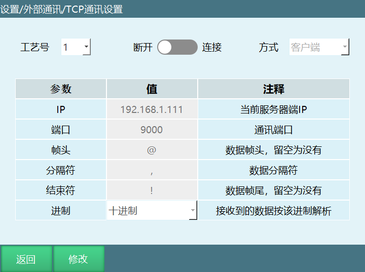
Parameter Description:
Process Number: Supports 9 process numbers.
Connection Switch: In client mode, gray means disconnected, green means connected. In server mode, gray means connection closed, green means connection open.
Mode: Controller acts as server or client. (When the controller is client or server, different process numbers can be used to communicate and send/receive data with multiple external devices.
Note: When the controller is a client connecting to multiple server devices with multiple process numbers, the IP and port of different process numbers cannot be the same. When the controller is a server connecting to multiple client devices with multiple process numbers, the port cannot be the same.
IP: When the connection mode is server, this is the controller IP and does not need to be modified. When the connection mode is client, the controller acts as client, and this IP is the external communication device's IP.
Port: When the mode is server, it is the local listening port for client connection. When the mode is client, it is the port to connect to the server.
Frame Header: During data communication, the frame header when the controller receives messages from external devices, can be modified.
Delimiter: During data communication, the delimiter when the controller receives messages from external devices, can be modified.
End Character: During data communication, the end character when the controller receives messages from external devices, can be modified.
Base: Parse the decimal or hexadecimal data to be received as decimal and output.
Description: When hexadecimal is selected, after executing the parse instruction, the data is parsed as decimal to the selected variable. For example, data sent by external communication device (@,123,100,120,!) will parse three data as decimal (291, 256, 288) output.
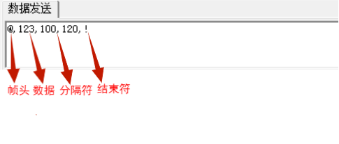
Note: When TCP communication connects, first set the controller IP and external device IP to the same subnet, such as 192.168.1.xxx. If the controller is set as client, the external device is server. Then set the IP and port in the network settings to be consistent with the IP and port in the external device network debugging software. Turn on the connection switch, and a connection success message will appear.
Network Communication Instructions
SENDMSG - Send Data
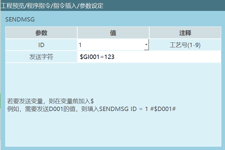
Format: SENDMSG [Instruction Name] ID=1 [Process Number] #DATA# [Data to Send].
Function: This instruction is used to send data to connected external devices. By selecting the corresponding process number, strings and variables can be sent. Strings and variables can be sent mixed. When sending messages to external devices through this instruction, the frame header, delimiter, and end character set in the "Settings-TCP Communication Settings" interface need to be used.
Note: If you want to send variables, add $ before the variable.
Parameters:
| ID | TCP communication process number |
|---|---|
| Send Character | Send data to connected network device. Can send string format data and variable values. To send variables, add $ symbol before the target variable. For example: SENDMSG ID = 1 #$D001#. If the target variable D001 has a value, when executing the send character data instruction, the network receives the variable value. If the target variable D001 has no value, the network receives 0. |
Example:
- NOP
- OPENMSG ID= 1
- SET D001 = 12.23
- SENDMSG ID = 1 #$D001#
- CLOSEMSG ID = 1
- END
Example description: After TCP communication is successful, send the variable value of D001 to the external communication device.
PARSEMSG - Parse Data
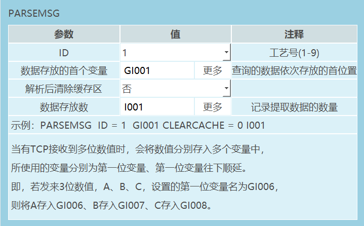
Format: PARSEMSG [Instruction Name] ID=1 [Process Number] I001 [First Variable for Data Storage] CLEARCACHE=0 [Whether to clear cache, "0" don't clear, "1" clear] 0 [Record data count, "0" don't record, "1" record].
Function: This instruction is used to parse a set of data from external devices and store the data into multiple variables.
Parameters:
| ID | TCP communication process number |
|---|---|
| First Variable for Data Storage | Store queried data in variables. Variable types: integer, floating-point, string. For example: TCP receives multi-digit values A, B, C. The first variable is GI001, so A is stored in GI001, B in GI002, C in GI003. |
| Clear Cache After Parse | No: After parsing, the cache is not cleared. When the external device has not sent new data, the parsed data will always be the cached value. After the external device resends data, new data can be parsed. Yes: After parsing, the cache is cleared. When the external device has not sent new data, parsing cannot get data. After the external device resends data, new data can be parsed. |
| Data Count Record | Record the number of sent data. Variable: Store the number of sent data into the selected variable. For example: TCP receives 3-digit values, data storage variable GI001, execute parse instruction GI001=3. Not Used: Don't record the number of sent data. When selecting not to use, the input box is grayed out. |
Example:
- NOP
- OPENMSG ID= 1
- PARSEMSG ID = 1 I001 CLEARCACHE = 0 GI001
- CLOSEMSG ID = 1
- END
Example description: After network communication is successful, run the parse instruction. Data sent by the external device is stored starting from the first variable I001, sequentially following the sent count. The data count is stored in variable GI001.
READCOMM - Read Data
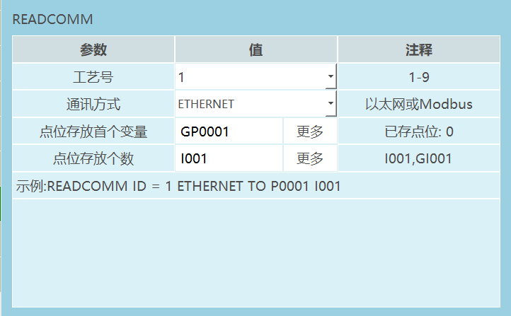
Format: READCOMM [Instruction Name] ID=1 [Process Number] ETHERENT, MODBUS [Communication Method] P/GP [Point Storage Variable] I001 [Point Storage Count].
Function: Read points sent via Ethernet or Modbus communication and store the points into variables.
Parameters:
| Parameter | Description |
|---|---|
| Process Number | TCP communication process number |
| Communication Method | Ethernet communication, Modbus communication |
| First Point Storage Variable | Store sent points into the selected position variable (P, GP) |
| Point Storage Count | Use variable (INT/GINT) to record the number of sent points |
Note: When selecting different communication methods to send points, pay attention to the format, otherwise point data cannot be written to variables.
Ethernet Communication: When sending points, refer to "INEXBOT Read Instruction Ethernet Point Communication Protocol".
Modbus Communication: Point settings can be found in External Transfer Point - Communication Method.
Example:
- NOP
- OPENMSG ID= 1
- READCOMM ID = 1 ETHERENT TO GP001 IOO1
- CLOSEMSG ID = 1
- END
Example description: Send points according to "INEXBOT Read Instruction ETHERENT Point Communication Protocol". After network communication is successful, the read point instruction will save the sent point data to variable GP0001, and the point count to variable I001.
OPENMSG - Open Data
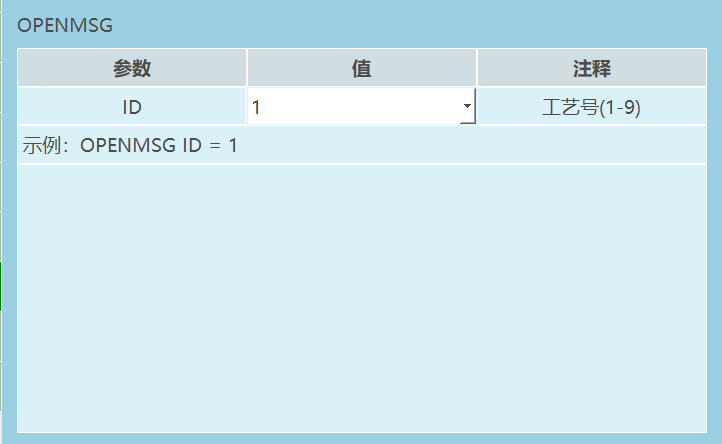
Format: OPENMSG [Instruction Name] ID = 1 [Process Number].
Function: Open network communication.
Parameters:
| Parameter | Description |
|---|---|
| ID | TCP communication process number, range [1,9] |
Example:
- NOP
- OPENMSG ID= 1
- SENDMSG ID = 1 #TEST#
- CLOSEMSG ID = 1
- END
Example description: Execute the open data instruction. After the controller communicates successfully with the external device, data can be sent and received.
CLOSEMSG - Close Data
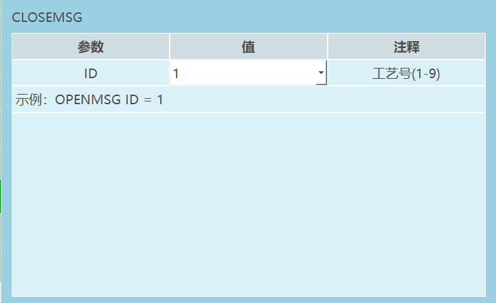
Format: CLOSEMSG [Instruction Name] ID = 1 [Process Number].
Function: Close network communication.
Parameters:
| Parameter | Description |
|---|---|
| ID | TCP communication close process number, range [1,9] |
Example:
- NOP
- OPENMSG ID= 1
- SENDMSG ID = 1 #TEST#
- CLOSEMSG ID = 1
- END
Example description: Execute the close data instruction. The controller disconnects from the external device.
PRINTMSG - Print Message
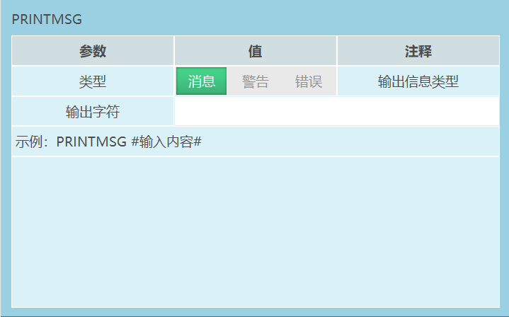
Format: PRINTMSG [Instruction Name] 0,1,2 [Type: Message, Warning, Error] #Content# [Output Character].
Function: Output defined message content through the print notification bar.
Parameters:
| Type | Message: White notification bar displayed on teach pendant interface when instruction is executed |
|---|---|
| Warning | Yellow warning notification bar displayed on teach pendant interface when instruction is executed |
| Error | Red error notification bar displayed on teach pendant interface when instruction is executed, and servo powers off |
| Output Character | Content displayed on teach pendant interface when printing notification bar. To print variables, add $ before the variable. For example $GD001. When inputting a variable, the notification bar prints the variable value when the instruction is executed |
Example:
- NOP
- PRINTMSG 0 #This is a message#
- PRINTMSG 1 #This is a warning#
- PRINTMSG 2 #This is an error#
- END
Example description: Execute instruction. The teach pendant interface displays white message notification, yellow warning notification, and red error notification respectively.
MSG_CONNECTION_ST - Get Message Connection Status
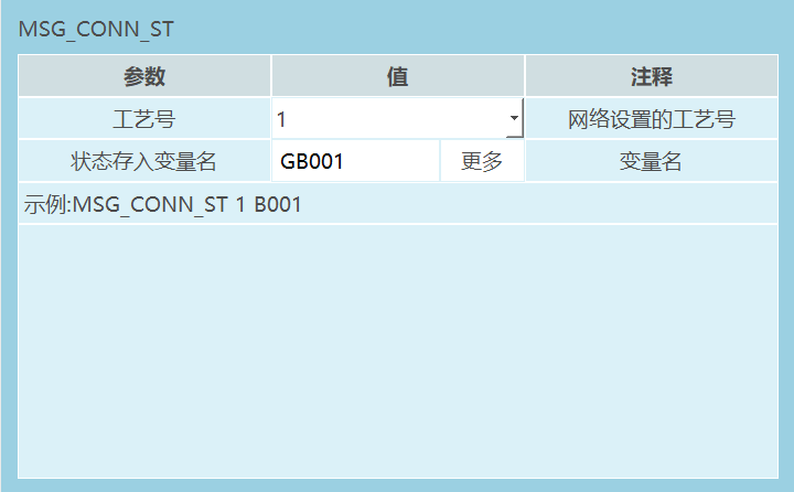
Format: MSG_CONNECTION_STATUS [Instruction Name] 1 [Process Number] GB001 [Current connection status "0" disconnected, "1" connected].
Function: Get the connection status of a process number in the network settings.
Parameters:
| Parameter | Description |
|---|---|
| Process Number | Process number selected in TCP communication settings interface |
| Status Storage Variable | Current connection process number status represented by variable (BOOL, GBOOL) |
Example:
- NOP
- OPENMSG ID= 1
- MSG_CONNECTION_ST I GB001
- CLOSEMSG ID = 1
- END
Example description: Execute the open data instruction. If the controller communicates successfully with the external device, GB001=1. If communication fails, GB001=0.
Example Description
External communication device: Network debugging assistant. As shown:
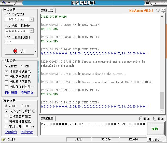
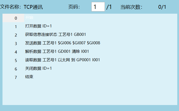
Execute the first instruction to connect the controller and external communication device.
Execute the second instruction. If the controller communicates successfully with the external device, variable GI001=1. If communication fails, GI001=0.
Execute the third instruction to send data to the external device. Send the values of variables GI006, GI007, GI008 to the external device, as shown below:
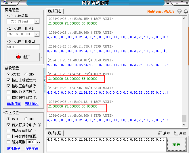
Execute the fourth instruction. After the external device sends data, parse the data. The parsed data is stored sequentially in variables based on the selected first variable.
Execute the fifth instruction. Store the point data sent by the external device into position variables. Store sequentially based on the selected first variable, as shown below:
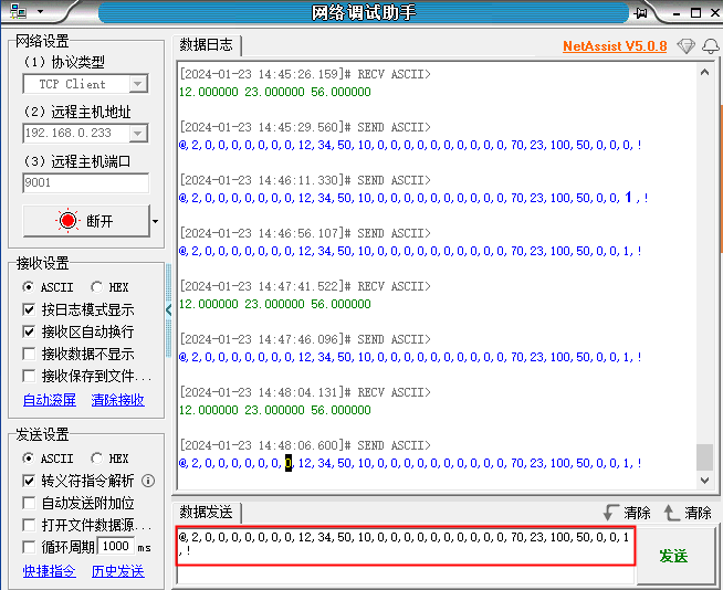
- Execute the sixth instruction to close the connection between the controller and external communication device.
Notes:
When external devices send points, they must follow "INEXBOT Read Instruction Ethernet Point Communication Protocol", as shown in the table.
When sending data, the frame header, delimiter, and end character must be consistent with the TCP communication settings interface.
| Serial Number | Meaning | Value |
|---|---|---|
| 1 | Point count | |
| 2 | Coordinate system | 0-joint; 1-Cartesian; 2-tool; 3-user |
| 3 | Angle unit | 0-degree; 1-radian |
| 4 | Left/Right hand | 0-none; 1-left hand; 2-right hand |
| 5 | Tool number | 0-none; 1-999 |
| 6 | User coordinate number | 0-none; 1-999 |
| 7 | Reserved | |
| 8 | Reserved | |
| 9 | Coordinate 1 | |
| 10 | Coordinate 2 | |
| 11 | Coordinate 3 | |
| 12 | Coordinate 4 | |
| 13 | Coordinate 5 | |
| 14 | Coordinate 6 | |
| 15 | Coordinate 7 |
External Transfer Points
Parameter Settings
External communication can use Modbus. Set parameters in "Settings - External Communication - Modbus Settings - Modbus Parameters" interface (also refer to Modbus related manual).
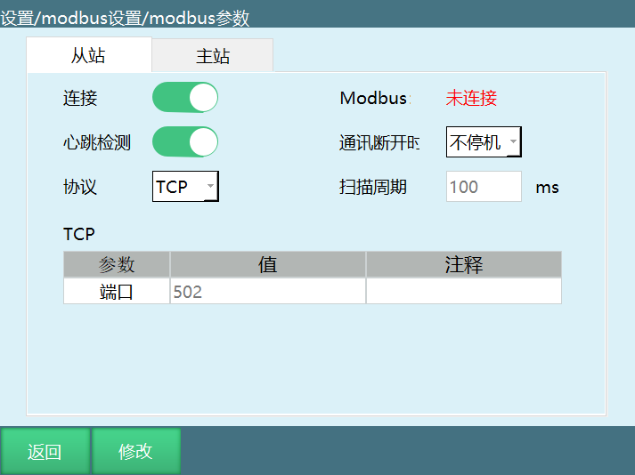
Connection: Modbus switch. After turning on, detect Modbus signal.
Heartbeat Detection: After turning on, used to detect the send/receive frequency between Modbus and controller. After disconnecting Modbus, heartbeat detection shows data send/receive closed.
Modbus: Displays the connection status between Modbus and controller.
When communication disconnects: No Stop: When Modbus slave disconnects and communication breaks, it will not stop running or power off.
Stop: When Modbus slave disconnects and communication breaks, it will stop running or power off.
Scan Cycle: The frequency at which the system scans data within the Modbus range.
On this interface, you can set whether Modbus connects, the protocol used for Modbus connection, whether this controller is Modbus master/slave, and various parameters when connected.
Communication Method
Due to address code limitations, for too many points, they need to be sent in batches, with a maximum of 30 points per send.
As long as the controller and PLC are connected, points can be sent. The controller will automatically store them.
| Purpose | Address Code | Process |
|---|---|---|
| All points send flag | 1001 | PLC sets to 1 when sending points, sets to 2 when sending ends, controller sets to 0 after receiving all. |
| Single send flag | 1002 | PLC sets to 1 when sending points, controller sets to 0 after receiving, PLC sets to 1 again for next send. |
| Single send point count | 1003 | Number of points sent by PLC at once, maximum 30. |
| Point storage data | Based on count | Detailed below. |
| Frame number per send | 1004 | Each point send must change the frame number, cannot be the same as last time. |
| Clear controller point queue flag | 1005 | To discard the point queue already sent to controller, PLC sets to 1, controller sets to 0 after clearing. |
Point storage data:
One point data includes 1 coordinate system and 6 axis values (for four-axis robot, includes 1 coordinate system and 4 axis values).
| Point i | Address Code | Notes |
|---|---|---|
| Coordinate system | 1010+20*(i-1) | 1<=i<=32 |
| In use | 1011+20*(i-1) | 1<=i<=32; send 0 to use, send 1 to not use |
| Axis j value | 1010+2+20*(i-1)+2*(j-1) | 1<=i<=32, 1<=j<=9, axis value uses float type, so occupies 2 addresses |
Example:
Need to send 88 points. Since only 32 can be sent at a time, it needs to be divided into 3 sends with counts of 32, 32, 24.
Process:
PLC sets 1003 to 32, sets values for each address code used for point storage data, sets 1001 to 1, sets 1002 to 1.
Controller detects 1002 is 1, 1001 is 1, retrieves data from point storage address codes based on the value of 1003, then sets 1002 to 0.
PLC detects 1002 is 0, sets 1003 to 32, sets point storage address code data, then sets 1002 to 1.
Controller detects 1002 is 1, 1001 is 1, retrieves data from point storage address codes based on the value of 1003, then sets 1002 to 0.
PLC detects 1002 is 0, sets 1003 to 24, sets point storage address code data, sets 1001 to 2, sets 1002 to 1.
Controller detects 1002 is 1, 1001 is 2, retrieves data from point storage address codes based on the value of 1003, then sets 1002 to 0, and sets 1001 to 0.
AI Retrieval Q&A (Q&A for Retrieval)
Q: What to do when TCP communication connection fails?
A: Check if the network connection is normal, ensure IP address and port settings are correct. Confirm if the TCP communication parameter connection enable switch is turned on. Verify if the firewall is blocking the TCP connection. Ensure the controller and external device are in the same network. Check if the network debugging software configuration is correct.
Q: How to distinguish TCP server and client?
A: Server: The party that passively waits for connection. When the controller acts as server, external devices can actively connect. Client: The party that actively initiates connection. When the controller acts as client, it needs to connect to an external server. Choose the controller as server or client based on actual application scenarios.
Q: What data types does TCP communication support?
A: TCP communication supports multiple data types, including strings, integers, floating-point, etc. Strings and variables can be sent using the SENDMSG instruction. Received data can be parsed and stored in different types of variables using the PARSEMSG instruction.
Q: How to modify the TCP communication port number?
A: Modify the port number in TCP communication parameter settings. In server mode, the port is the local listening port. In client mode, the port is the port to connect to the server. After modification, reconnection is needed to take effect. Ensure the firewall allows access to that port.
Q: What is the difference between TCP communication and Modbus communication?
A: TCP communication is a general network communication protocol that supports custom data formats with high flexibility. Modbus communication is a standard industrial communication protocol with fixed data format and address codes. TCP communication requires setting frame header, delimiter, and end character. Modbus communication uses standard address codes for data reading and writing.
Q: How to verify if TCP communication connection is successful?
A: Check the connection status in TCP communication parameter settings interface. After successful connection, the connection switch displays green. Use the MSG_CONNECTION_ST instruction to get the connection status. Try sending and receiving data to verify if data transmission is normal. Check the controller logs to confirm if there are connection failure records.
Q: Will TCP communication affect normal robot operation?
A: TCP communication is designed as a low-priority task and will not affect normal robot operation. The data send/receive process is fast and will not occupy too many controller resources. It is recommended to set the data send/receive frequency reasonably to avoid overly frequent operations. If the communication volume is large, consider using more efficient network equipment.
Q: How to send variable data?
A: When using the SENDMSG instruction to send data, add $ symbol before the variable. For example: SENDMSG ID=1 #$D001# will send the value of variable D001 to the external device. Strings and variables can be sent mixed. Ensure the variable has been assigned a value, otherwise the sent value will be 0.
Q: How to parse received data?
A: Use the PARSEMSG instruction to parse received data. Set the first variable for data storage, and the parsed data will be stored sequentially in subsequent variables. You can choose whether to clear the cache. When not clearing the cache, cached data will always be parsed. You can record the number of received data.
Q: How to troubleshoot TCP communication problems?
A: Check network connection and IP address settings. Verify if the firewall allows TCP port access. Check controller logs to understand specific error information. Check if TCP communication parameter settings are correct. Try using the network debugging assistant for testing. Ensure the communication protocol between the controller and external device is consistent.