New Dual-Robot Function
First set up two robots (different types are also acceptable)
Dual-Robot Linkage Mode Configuration
Linkage mode requires Robot 1 and Robot 2 to each calibrate their tool hands
Settings / Robot Parameters / Calibrate World Coordinate System
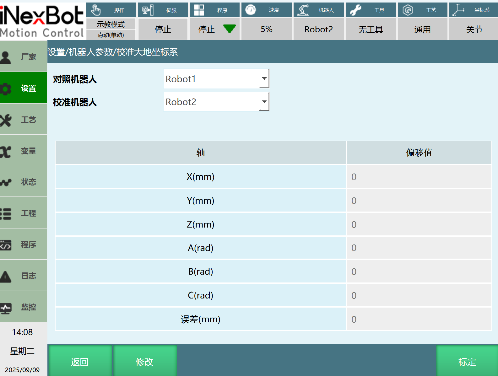
Reference Robot: As a reference, generally the master robot.
Calibration Robot: Calibrated relative to the reference robot, generally the slave robot.
Error: Error should generally not exceed 10, otherwise recalibration is needed.
- Click [Calibrate] to enter the calibration interface
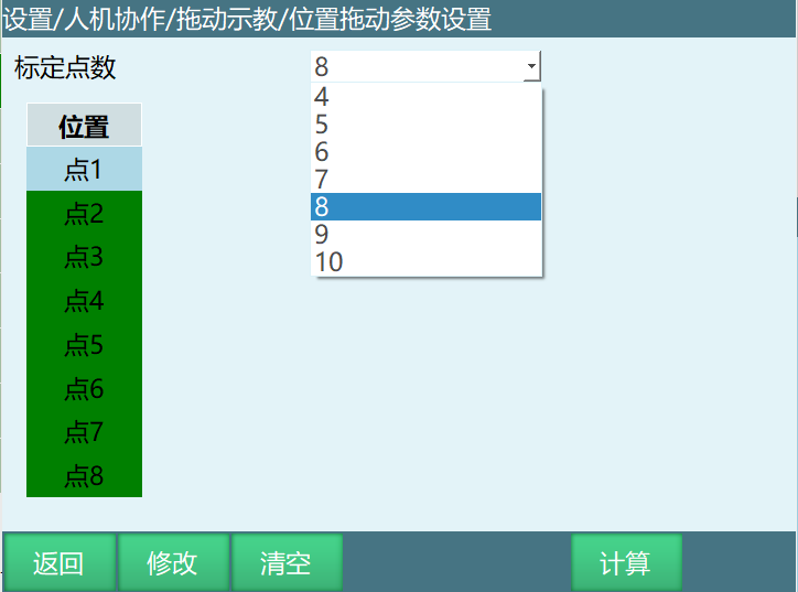
Modify: Click modify to calibrate
Clear: Clear calibration parameters
Calculate: Calculate calibration results
Note: Calibration point selection is generally 6 or 9 points, which is the average of x, y, z. For example, moving x 3 times, y 3 times, z 3 times equals 9 points. Theoretically, more points result in greater accuracy.
- After calibration is complete, in the calibration robot's Settings / User Coordinate Calibration interface, select [Linkage Coordinate System] for [Type], [Robot], and select [1] for the number
User coordinates set as linkage coordinate system are in linkage mode; selecting other settings for static coordinate system is single-robot mode.
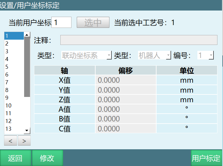
- After setup, switch to Robot 1, power on and jog Robot 1. At this time, Robot 2 will also follow Robot 1's movement.
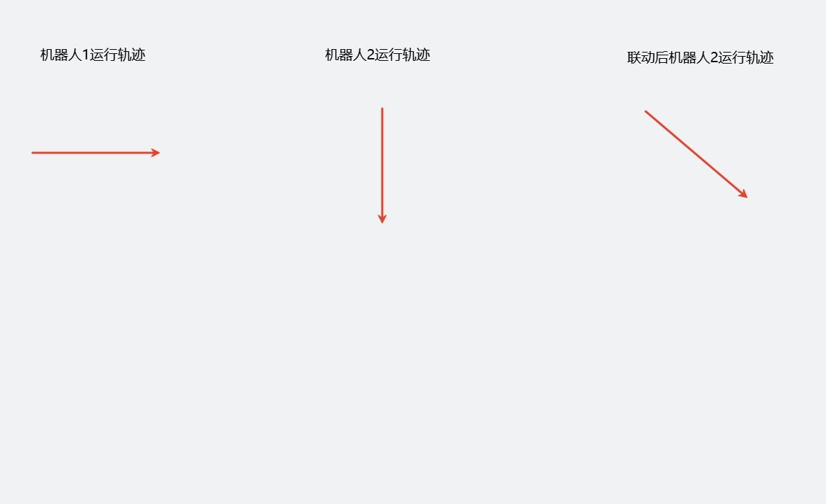
In linkage mode, Robot 2 will follow Robot 1's trajectory direction while moving along its taught trajectory.
Robot movement effect in linkage mode is shown in the figure.
Run Mode Linkage
Prerequisites: Robot 1 is the reference robot, Robot 2 is the calibration robot
Create Robot1 and Robot2 job files
Insert motion instructions in Robot 1.
Insert user coordinate switch in Robot 2 (the switched coordinate is the linkage user coordinate.)
Because at this time, switching user coordinates in Robot 2 will execute immediately, Robot 2 will end the program. Three methods can be used to maintain linkage with Robot 1.
a. Robot 2 enables loop mode
b. Estimate Robot 1's motion time and add a delay instruction
c. Use multi-machine coordination instructions, inserting wait synchronization points in both Robot 1 and Robot 2.

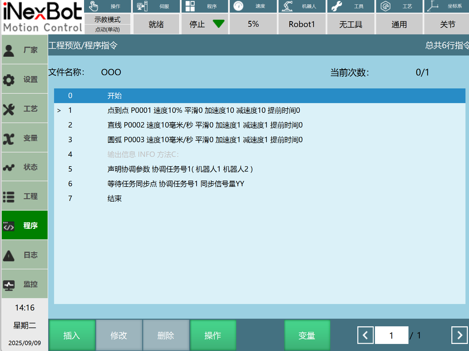
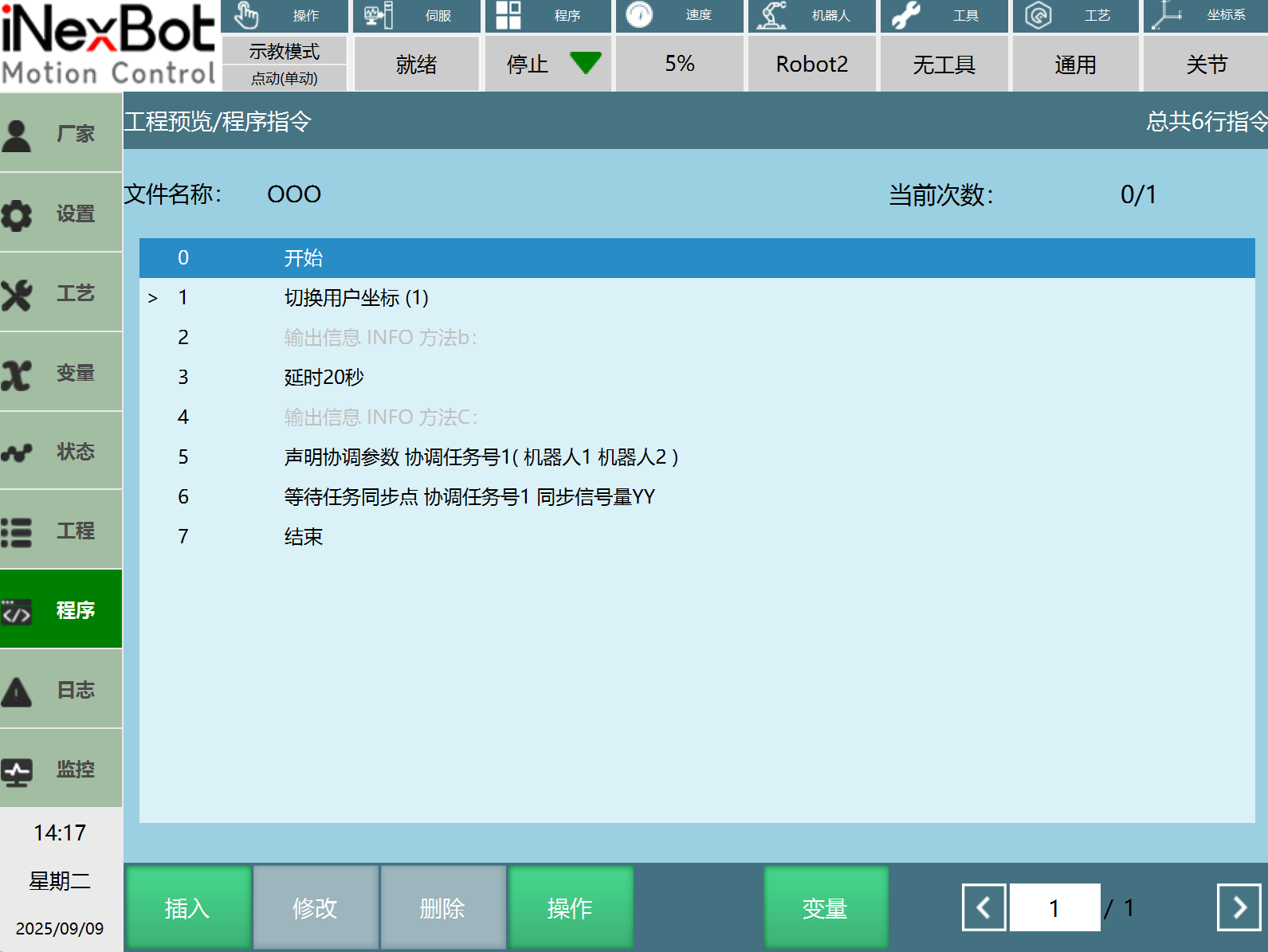
Robot1 and Robot2 servo ready
Switch to run mode and select RobotAll
At this point, you enter the multi-machine dedicated interface. Click Start to begin.
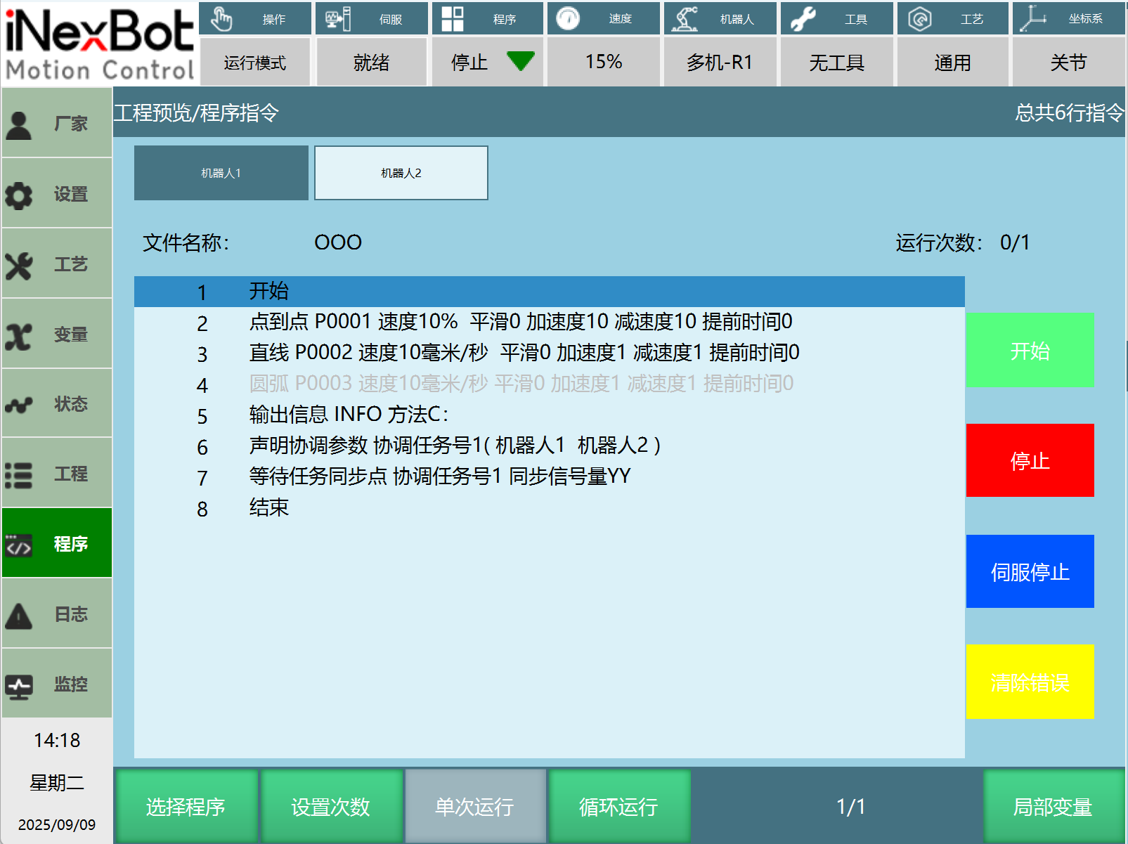
Interface Button Functions
Select Program: Select the job files to run for Robot 1 and Robot 2
Start: Start running the selected program for Robot 1/Robot 2
Stop: Stop Robot 1/Robot 2
Servo Stop/Servo Ready: Stop or ready the servo for Robot 1/Robot 2
Clear Error: Clear errors for Robot 1/Robot 2
To start both robots simultaneously, press [Start] on the teach pendant.
To pause both robots simultaneously, press [Stop] on the teach pendant.
To individually start Robot 1, click [Robot 1], then click [Start] as shown in the figure. Robot 1 starts working. Click [Stop] to pause Robot 1.
To individually start Robot 2, first click [Robot 2], then click [Start]. Robot 2 starts working. Click [Stop] to pause Robot 2.
Single Machine Then Link Then Single Machine
Prerequisites: Robot 1 is the reference robot, Robot 2 is the calibration robot
Create Robot1 and Robot2 job files.
Insert the required motion instructions for each single machine, ensuring the last instruction on both sides is the dual-robot start point. Robot 2 must ensure the linkage user coordinate system is not in use during machine operation.
Due to speed differences, Robot 1 and 2 may not arrive at the dual-robot start point simultaneously. Insert multi-machine coordination instructions, adding wait synchronization points in both Robot 1 and 2. This ensures both machines start dual-robot state simultaneously.
Insert motion instructions in Robot 1.
Insert user coordinate switch in Robot 2 (the switched coordinate is the linkage user coordinate.)
After the dual-robot section ends, insert multi-machine coordination instructions, adding wait synchronization points in both Robot 1 and 2. Before the synchronization points is dual-robot motion.
Switch to single machine: Robot 1 inserts instructions normally; Robot 2 inserts user coordinate system switch (this user coordinate system must be a static user coordinate system), then inserts motion instructions normally.
Robot1 and Robot2 servo ready
Switch to run mode and select RobotAll
At this point, you enter the multi-machine dedicated interface. Click Start to begin.
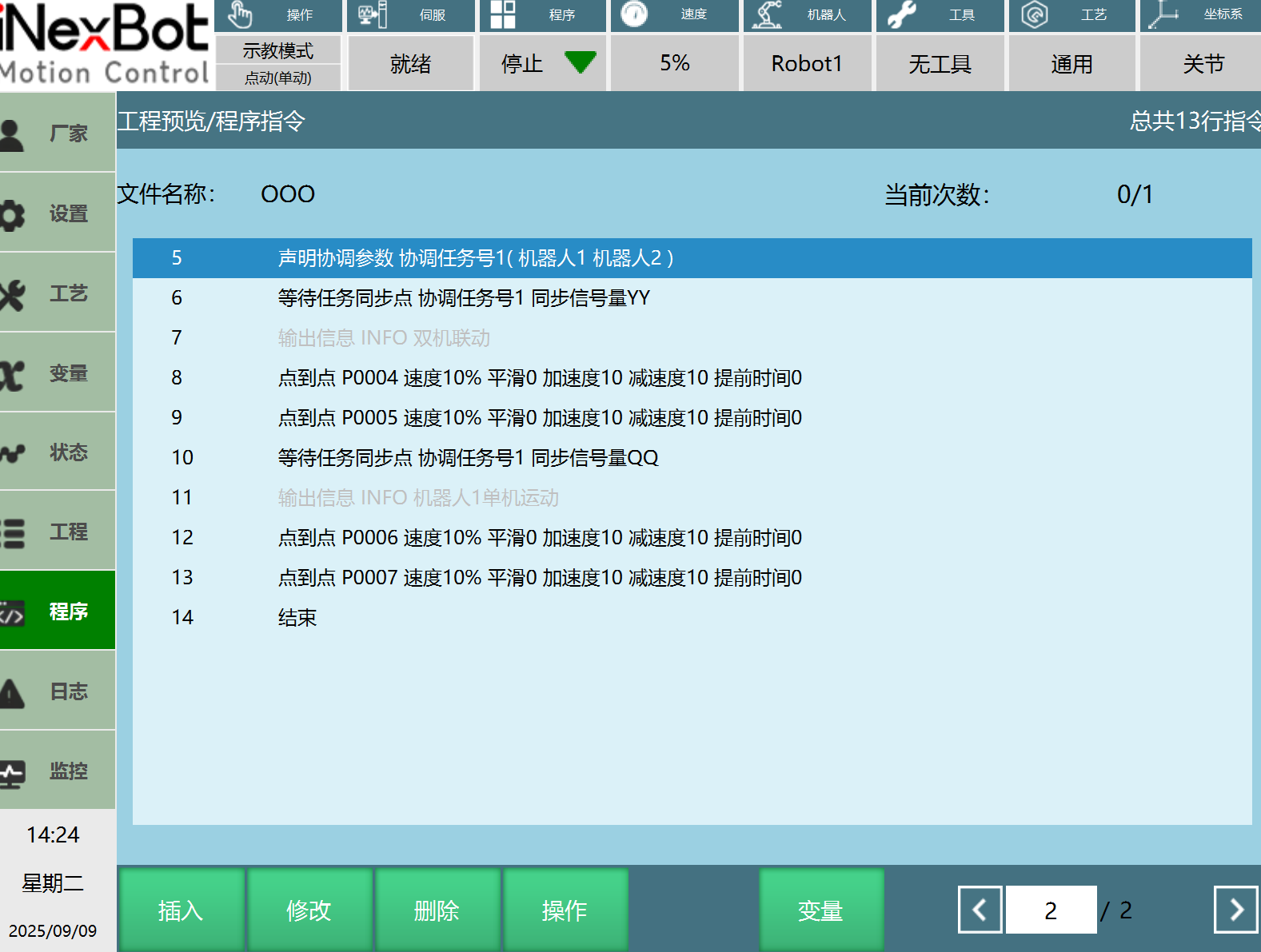
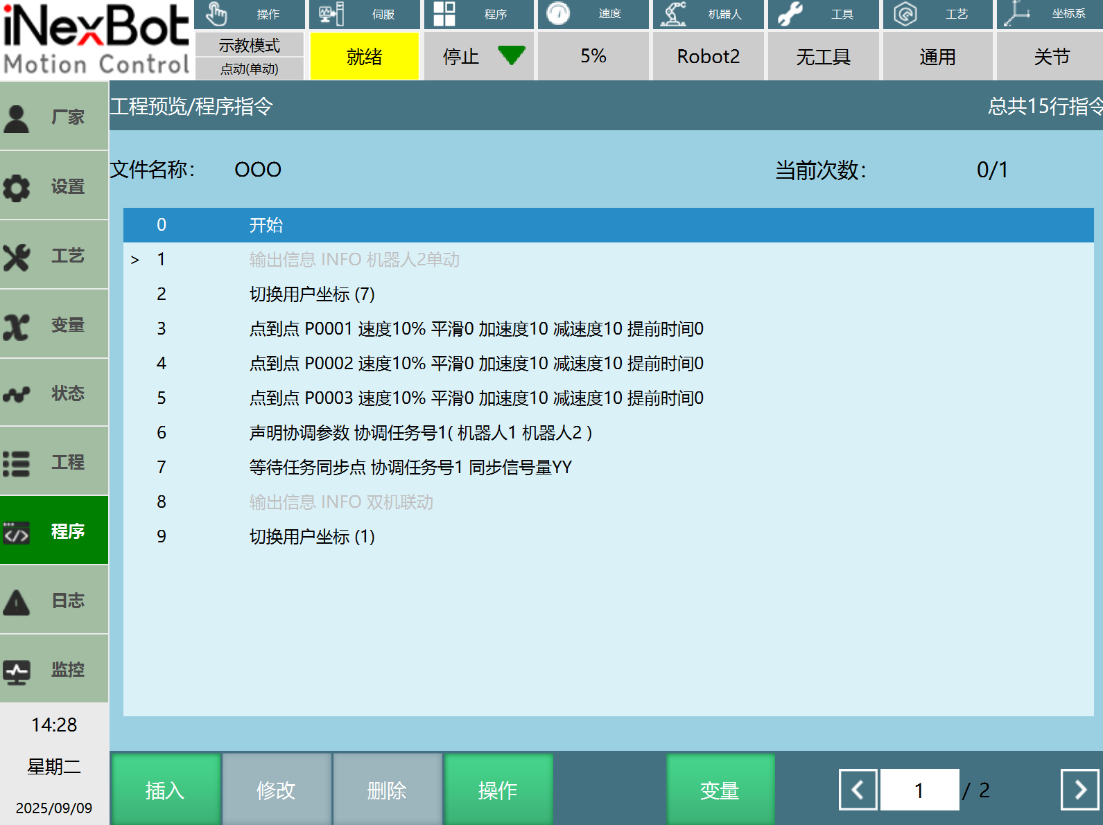
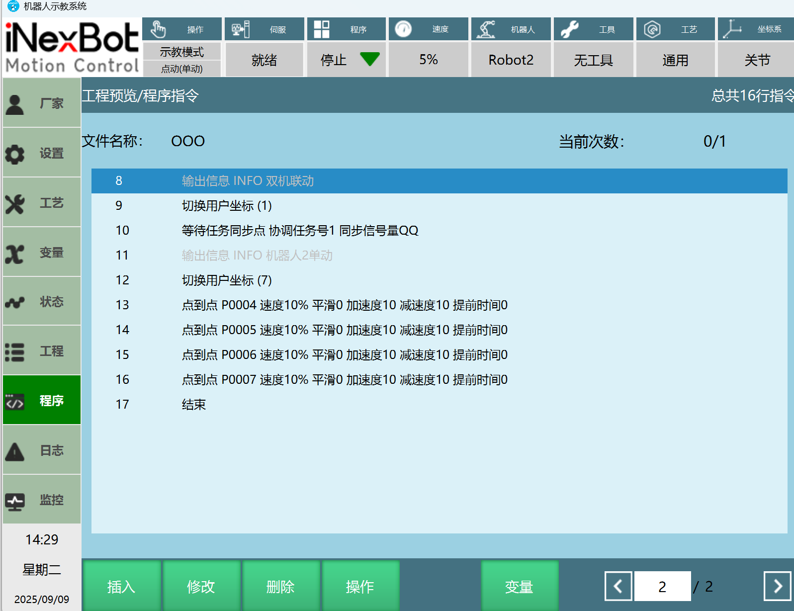
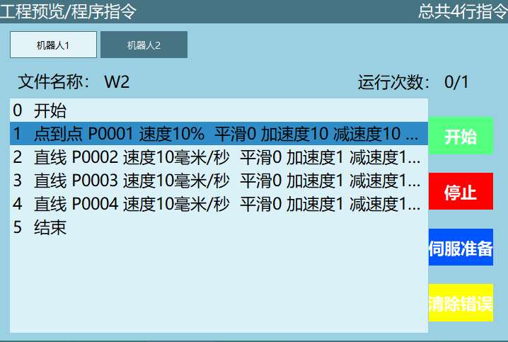
Reference job file examples are as follows:


Robot 1:
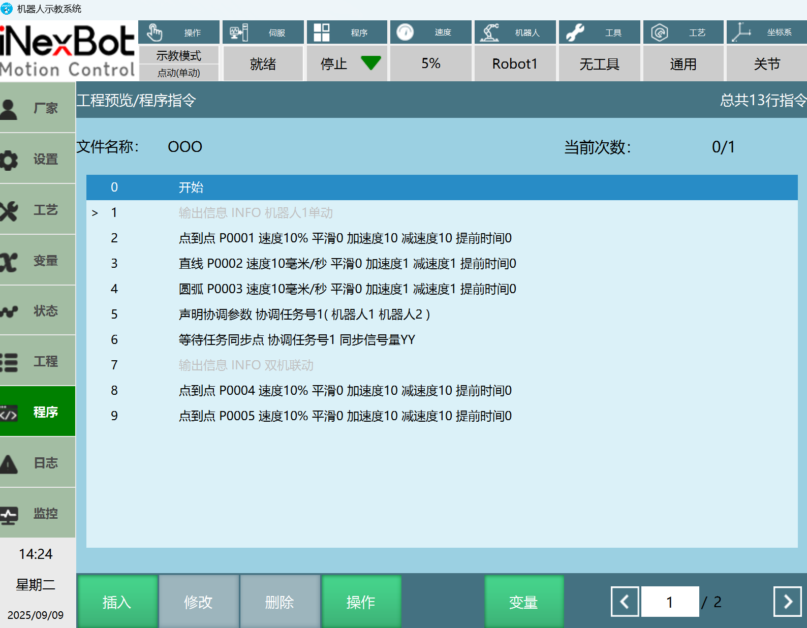
Robot 2:
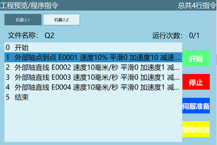
Dual-Robot with External Axis Motion
AI Retrieval Q&A (Q&A for Retrieval)
What operation needs to be completed first for dual-robot linkage mode configuration?
A: First, calibrate the tool hands of Robot 1 and Robot 2 separately, then enter the [Settings / Robot Parameters / Calibrate World Coordinate System] interface, distinguish the reference robot (master) and calibration robot (slave), and perform world coordinate system calibration. The calibration error must be controlled within 10, otherwise recalibration is needed.
In dual-robot linkage mode, how to switch to single-robot mode?
A: In the calibration robot's (usually Robot 2) [Settings / User Coordinate Calibration] interface, switch [Type] from [Linkage Coordinate System] to another static coordinate system to switch to single-robot mode. To reconnect, switch back to [Linkage Coordinate System] and complete the related configuration.