Conveyor Belt Tracking Process Manual
Process Introduction
Conveyor belt tracking refers to the robot using the user-input material point position and the corresponding encoder value when the material is at this position to calculate the material point position in real-time, and track the material through motion.
Click [Process] - [Conveyor Belt Tracking Process] - [Parameter Settings] to enter the conveyor belt tracking process parameter settings interface
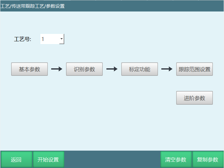
Clear Parameters: Clear parameters of the currently selected process number.
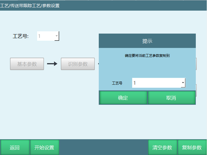
Copy Parameters: Copy all parameters of this process number to another process number.
Basic Parameters
Before setting all parameters, please select a process number in the "Parameter Settings" interface. Each process number saves all parameters. These basic parameters are for basic settings of the conveyor belt.
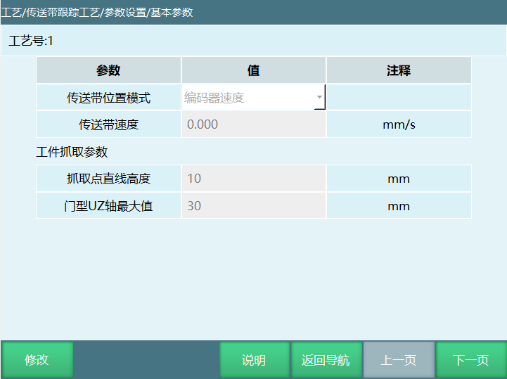
- Conveyor Belt Position Mode
Select Encoder Value: Normal conveyor belt calibration.
Select Constant Speed Setting: When constant speed setting is selected, it is independent of the encoder. Conveyor belt speed can be manually filled in for setting (after manually modifying the speed, the sensor needs to be recalibrated).
Note: When setting constant speed, sensor position calibration calculation has error; error factors: conveyor belt motion time interval is too large during calibration; solution: robot tool hand stops on the workpiece following path, calibrate when the workpiece passes the tool hand, can reduce error.
Select Encoder Speed: Use conveyor belt speed calculation after smooth filtering. Note: No longer supports conveyor belt dynamic speed adjustment and dynamic synchronization.
Conveyor Belt Speed: Current conveyor belt speed, read-only.
Workpiece Grasp Parameters
Grasp Point Linear Height: When the robot lifts, Z moves to the set length before moving X, Y coordinates (this value cannot be greater than arch height).
Description: The arch is when the robot receives the grasp coordinates, the robot needs to move to the workpiece position and grasp in an arch manner.
Arch UZ Axis Maximum Value: Maximum height of Z axis when robot moves in arch motion.
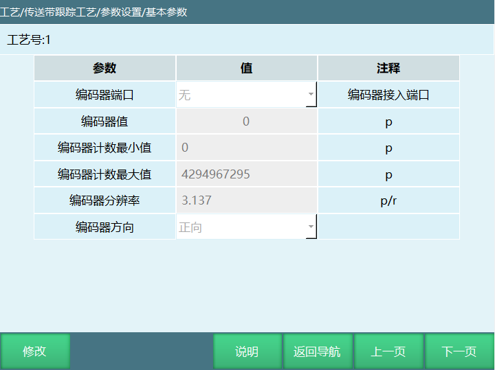
Encoder Port: Encoder connection port
Encoder Value:
After encoder connection is successful, automatically identify the current connected encoder value. This number can only be read, cannot be modified.
When the encoder value cannot be read successfully, it is generally divided into two situations: encoder interface wiring method is incorrect; encoder is connected to the wrong port position on the IO board.
Port position on the IO board can refer to the corresponding IO board definition diagram; encoder port wiring method can refer to the corresponding encoder definition diagram.
- Encoder Count Maximum and Minimum Values:
The maximum value that the encoder data processing module can count is based on the IO board used as the encoder data processing module. Current ranges are as follows:
Integrated drive version: 0-65535;
Nuodajia firmware below version 18: 0-1024
Nuodajia firmware version 18: -2147483648-2147483647;
R4C version: -2147483648-2147483647.
2200-A01 version: 0-4294967295.
- Encoder Resolution:
The unit pulse sent by the encoder when the conveyor belt rotates 1mm. This value is the calibration result.
- Encoder Direction:
Open the conveyor belt, observe whether the encoder value changes with the conveyor belt movement. If no change, the encoder is not recognized. If it changes with the conveyor belt movement, select the corresponding direction here. Note: Encoder value increasing is forward, decreasing is reverse.
Parameter Identification
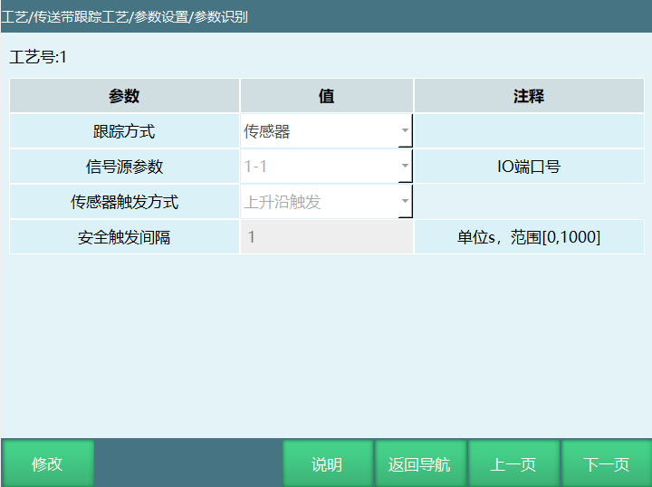
Tracking Method
Vision
Connect the controller and camera. Camera takes photo and sends workpiece coordinates. Wait for the workpiece to enter the tracking area. The robot will perform real-time tracking based on [position coordinates sent by vision].
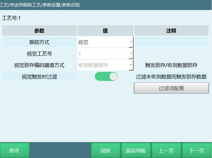
Vision Process Number: 1-9, select the corresponding process number for camera data reception.
Vision Latch Encoder Value Method:
i. Trigger Latch: Immediately latch the current conveyor belt encoder value when vision triggers photo. There may be cases where the photo is triggered and encoder value is latched but data is not received, so it needs to be used with the "Vision Trigger Filter" function. Each time vision is triggered, note: if the previous workpiece trigger did not receive vision data, discard the previously latched conveyor belt encoder data.
ii. Data Received Latch: Latch encoder value when receiving data sent by camera.
Vision Trigger Filter: Encoder value and vision data should have a corresponding relationship. This parameter is used to determine whether to filter the previous encoder latch value that did not receive data when vision triggers and latches new encoder value.
Sensor
Connect the sensor signal to the IO board, select the corresponding IO port for signal source: When the workpiece passes the sensor, the system obtains the signal and latches the conveyor belt encoder value. Wait for the workpiece to enter the tracking area. The robot will perform real-time tracking based on [sensor calibrated position coordinates].
Signal Source Parameters: Use IO to detect conveyor belt workpieces. Signal source parameters can select the sensor's corresponding IO port.
Sensor Trigger Method: IO rising edge and falling edge trigger. (Rising edge: refers to the edge trigger when IO signal changes from 0 to 1; falling edge: refers to the edge trigger when IO signal changes from 1 to 0)
Safety Trigger Interval: Sensor IO trigger needs to wait the set time before it can take effect again.
Sensor + Vision
Connect the sensor signal to the IO board and camera hardwired. Select the corresponding IO port for signal source: When the workpiece passes the sensor, the camera triggers photo through hardwired connection. Wait for the workpiece to enter the tracking area. The robot will perform real-time tracking based on [sensor calibrated position coordinates].
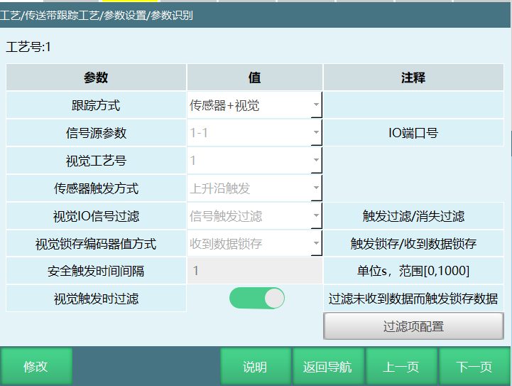
Signal Source Parameters: Use IO to detect conveyor belt workpieces. Signal source parameters can select the sensor's corresponding IO port.
Vision Process Number: 1-9, select the corresponding process number for camera data reception.
Sensor Trigger Method: IO rising edge and falling edge trigger. (Rising edge: refers to the edge trigger when IO signal changes from 0 to 1; falling edge: refers to the edge trigger when IO signal changes from 1 to 0)
Vision IO Signal Filter:
i. Trigger Filter: When the first workpiece triggers the sensor signal, and when the second workpiece triggers the sensor signal, if vision still hasn't returned data, discard the first workpiece's triggered sensor signal, then record the second workpiece's sensor signal. The first workpiece robot will not grasp. When the first workpiece triggers the sensor signal, and when the second workpiece triggers the sensor signal, if vision returns data, the robot will grasp normally.
ii. Signal Disappearance Filter: When the first workpiece triggers the sensor signal, and when the second workpiece's triggered sensor signal disappears, if vision still hasn't returned data, discard the first workpiece's triggered sensor signal, then record the second workpiece's sensor signal. The first workpiece robot will not grasp. When the first workpiece triggers the sensor signal, and when the second workpiece's triggered sensor signal disappears, if vision returns data, the robot will grasp normally.
Vision Latch Encoder Value Method: When the robot is running, using sensor and vision to grasp workpieces. At this time, there are workpieces passing the sensor, vision photographs to calculate workpiece position. During instruction execution, there are many uncertain factors and camera processing speed is slow, so the latch function exists.
i. Trigger Latch: Immediately latch the current conveyor belt encoder value when vision triggers photo. There may be cases where the photo is triggered and encoder value is latched but data is not received, so it needs to be used with the "Vision Trigger Filter" function. Each time vision is triggered, note: if the previous workpiece trigger did not receive vision data, discard the previously latched conveyor belt encoder data.
ii. Data Received Latch: Latch encoder value when receiving data sent by camera.
Safety Trigger Time Interval: Sensor IO trigger needs to wait the set time before it can take effect again.
Vision Trigger Filter: Encoder value and vision data should have a corresponding relationship. This parameter is used to determine whether to filter the previous encoder latch value that did not receive data when vision triggers and latches new encoder value.
Global Variable + Modbus
By monitoring global variables, when the variable is 1, latch encoder value and consider that the workpiece has arrived. Wait for the workpiece to enter the tracking area. The robot performs real-time tracking based on coordinates sent by [modbus] address. Note: modbus address is 2 digits per coordinate---X(1012-1013)Y(1014-1015)Z(1016-1017)
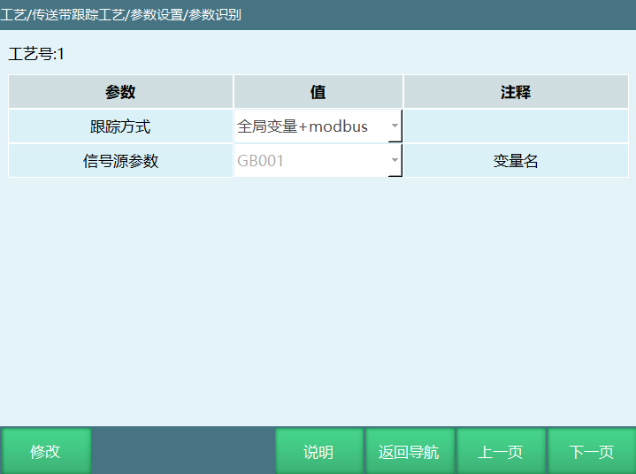
- Signal Source Parameters: Global variable GB001---990 (1 to latch encoder value and then modbus sends points through address code, 0 to not track).
Global Variable + Vision
Select the corresponding variable for signal source. When the global variable changes, latch the conveyor belt encoder value, camera triggers photo. Wait for the workpiece to enter the tracking area. The robot will perform real-time tracking based on [position coordinates sent by vision].
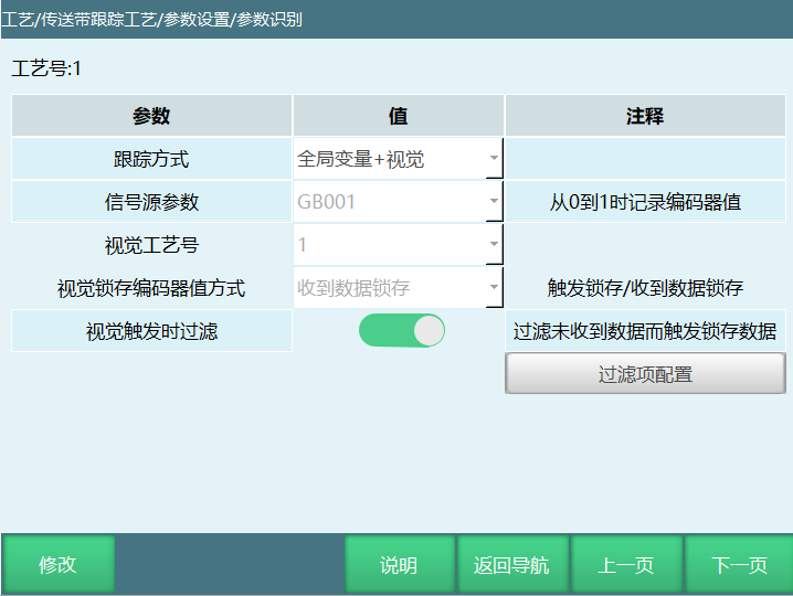
Signal Source Parameters: Global variable GB001---990 (1 to latch encoder value)
Vision Process Number: 1-9, select the corresponding process number for camera data reception.
Vision Latch Encoder Value Method:
i. Trigger Latch: Immediately latch the current conveyor belt encoder value when vision triggers photo. There may be cases where the photo is triggered and encoder value is latched but data is not received, so it needs to be used with the "Vision Trigger Filter" function. Each time vision is triggered, note: if the previous workpiece trigger did not receive vision data, discard the previously latched conveyor belt encoder data.
ii. Data Received Latch: Latch encoder value when receiving data sent by camera.
Vision Trigger Filter: Encoder value and vision data should have a corresponding relationship. This parameter is used to determine whether to filter the previous encoder latch value that did not receive data when vision triggers and latches new encoder value.
Filter Parameters
Applicable to converting coordinates received by vision from front and back positions to user coordinates. The back position needs to add the conveyor belt movement distance during the photo interval between front and back positions.
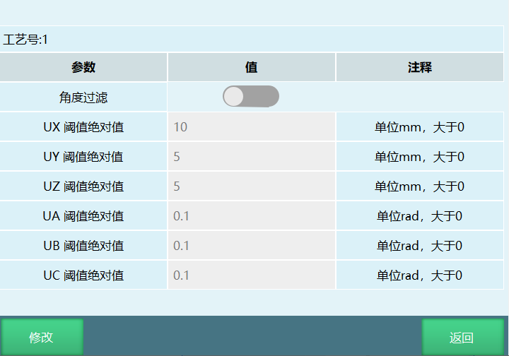
Angle Filter: Whether to filter UA, UB, UC.
Function Description: When the UX, UY, UZ, UA, UB, UC differences between two points are within the absolute threshold range, they will be filtered, otherwise they will not be filtered.
Comparison Process: Receive the first point coordinate, then receive the second point coordinate. The second point coordinate will be compared with the first point coordinate (Note: comparison process needs to add the conveyor belt movement distance between the two point coordinates). If the difference exceeds the threshold, the second point will be discarded. When receiving the third value, it will still be compared with the first point, and so on.
Calibration Function
Conveyor belt user coordinate system selection: select the user coordinate system that needs to be calibrated (currently supports 1-9)
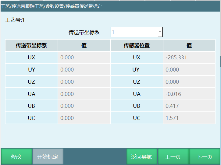
Linear Conveyor Belt Vision Type (Vision, Sensor+Vision, Global Variable+Vision) Calibration Steps
Note:
When the controller performs calibration, please select conveyor belt pixel coordinates or conveyor belt robot coordinates in the vision process.
The camera coordinate system XY plane needs to be basically parallel to the conveyor belt plane.
The camera coordinate X direction needs to be consistent with the conveyor belt movement direction; if not consistent, it will cause inaccurate calibration. If adjustment is needed, adjust the camera XY vision direction.
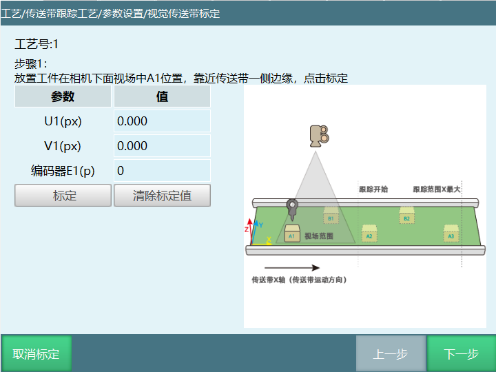
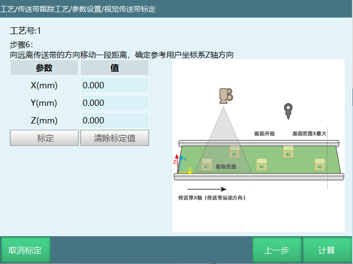
Step 1: Place the workpiece at position A1 in the camera's field of view, near one side edge of the conveyor belt, click calibrate. (Need to be powered on and normally obtain camera return coordinate data)
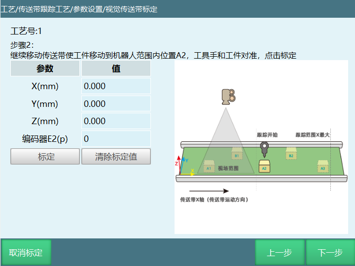
Step 2: Continue moving the conveyor belt to move the workpiece to position A2 within the robot range. Align the tool hand with the workpiece, click calibrate.
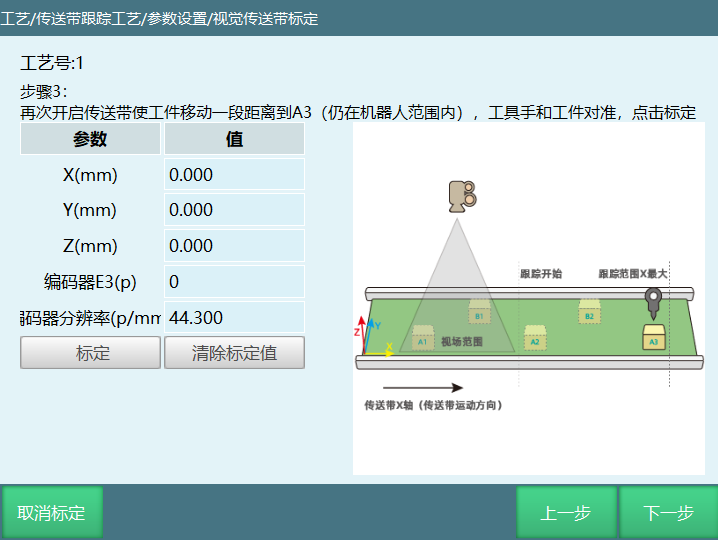
Step 3: Open the conveyor belt again to move the workpiece a distance to A3 (still within robot range). Align the tool hand with the workpiece, click calibrate.
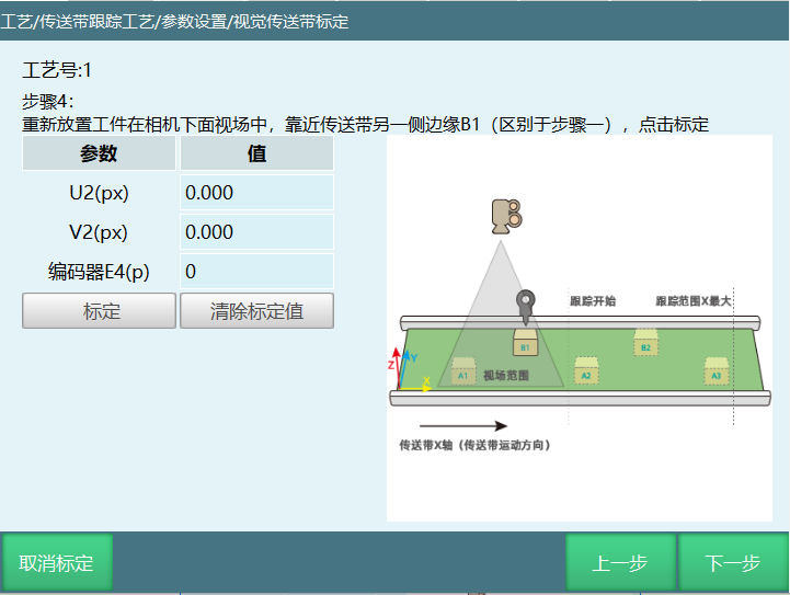
Step 4: Re-place the workpiece in the camera's field of view, near the other side edge B1 of the conveyor belt (different from step 1), click calibrate.
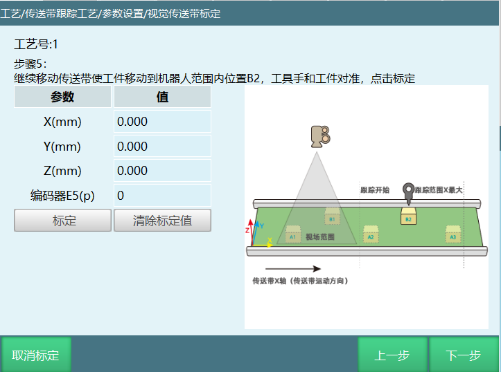
Step 5: Continue moving the conveyor belt to move the workpiece to position B2 within the robot range. Align the tool hand with the workpiece, click calibrate.
Step 6: Move a distance away from the conveyor belt to determine the reference user coordinate system Z axis direction, click calibrate.
Step 7: After the above steps are completed, click calculate.
Circular Conveyor Belt Vision Calibration
The conveyor belt coordinate system values are calculated after the conveyor belt calibration is completed.
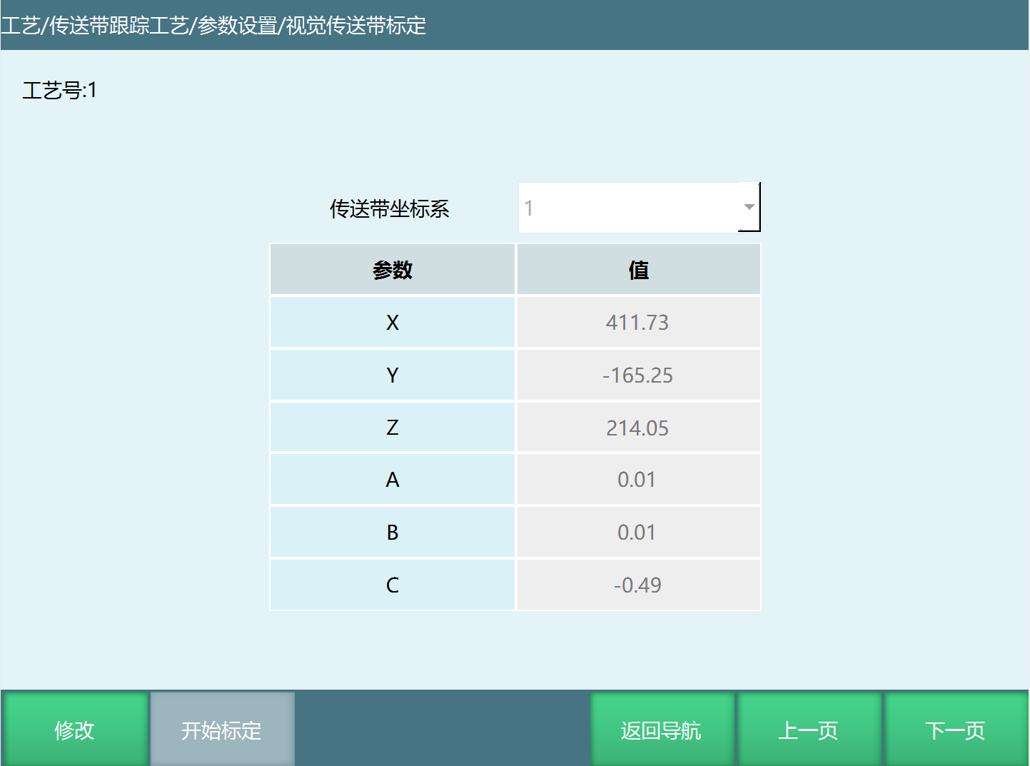
Conveyor belt calibration: Calculate the user coordinate system of the conveyor belt by calibrating 6 workpiece position points. Click [Modify], [Start Calibration] button to enter the calibration interface.
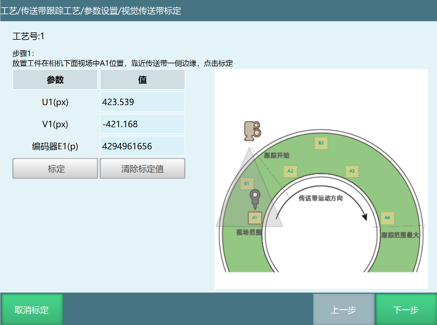
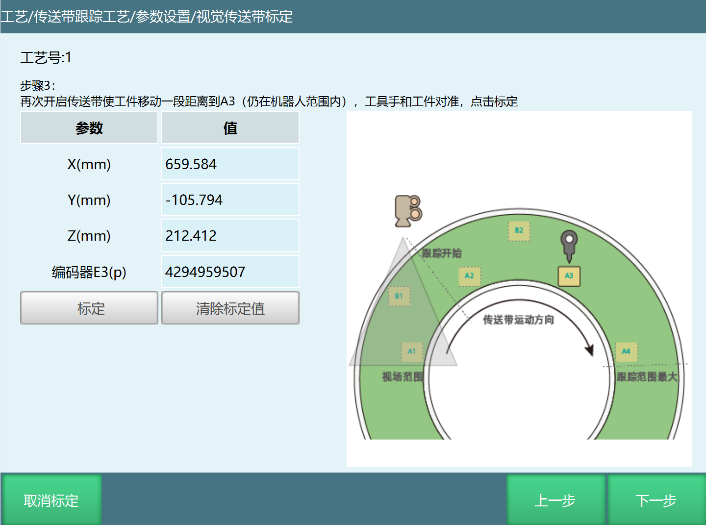
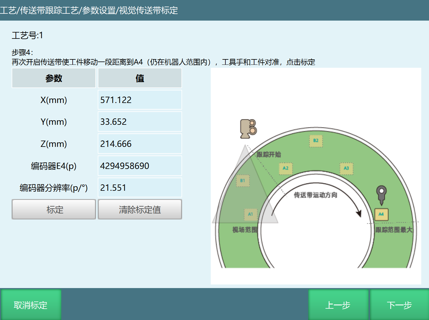
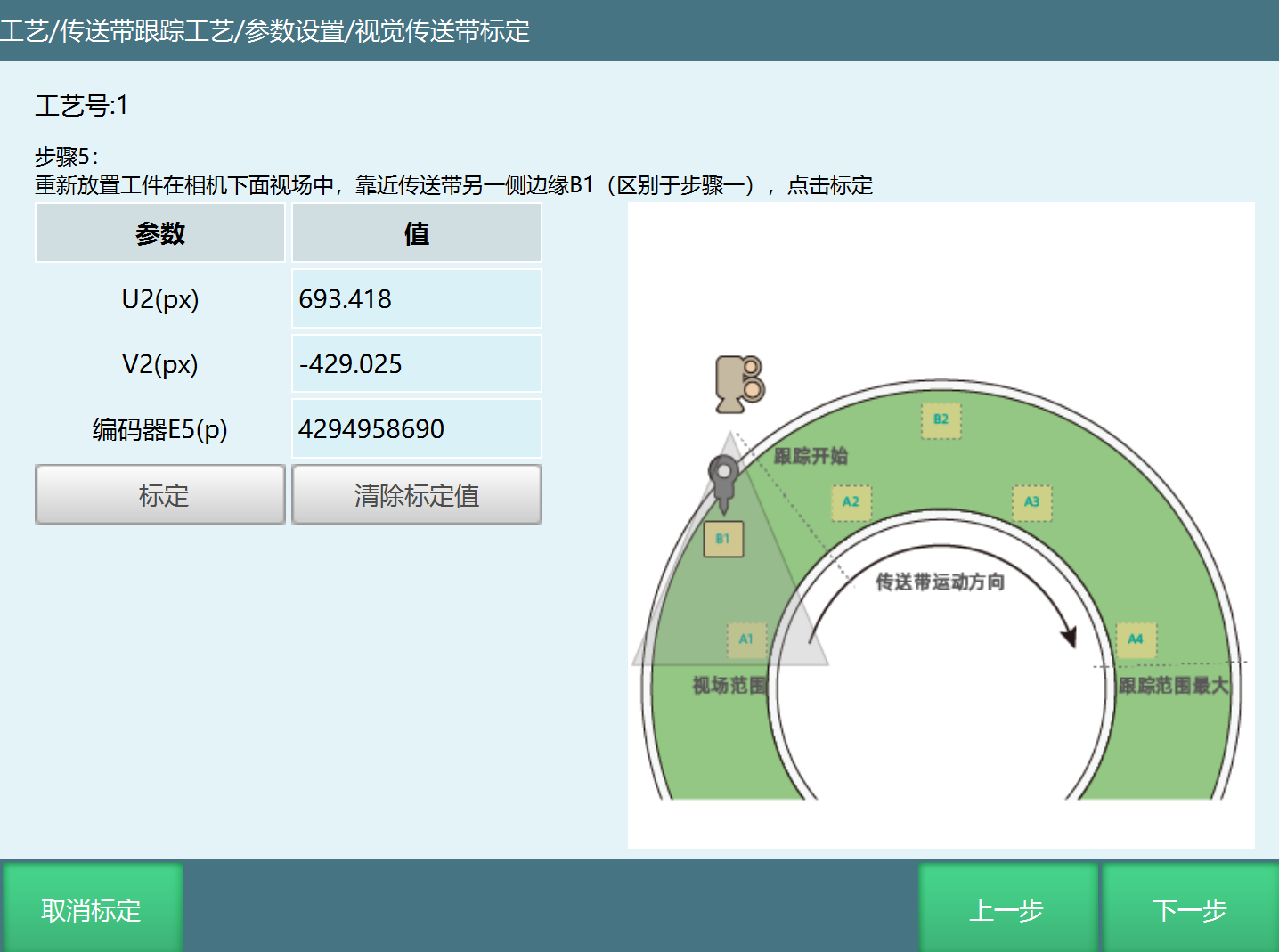
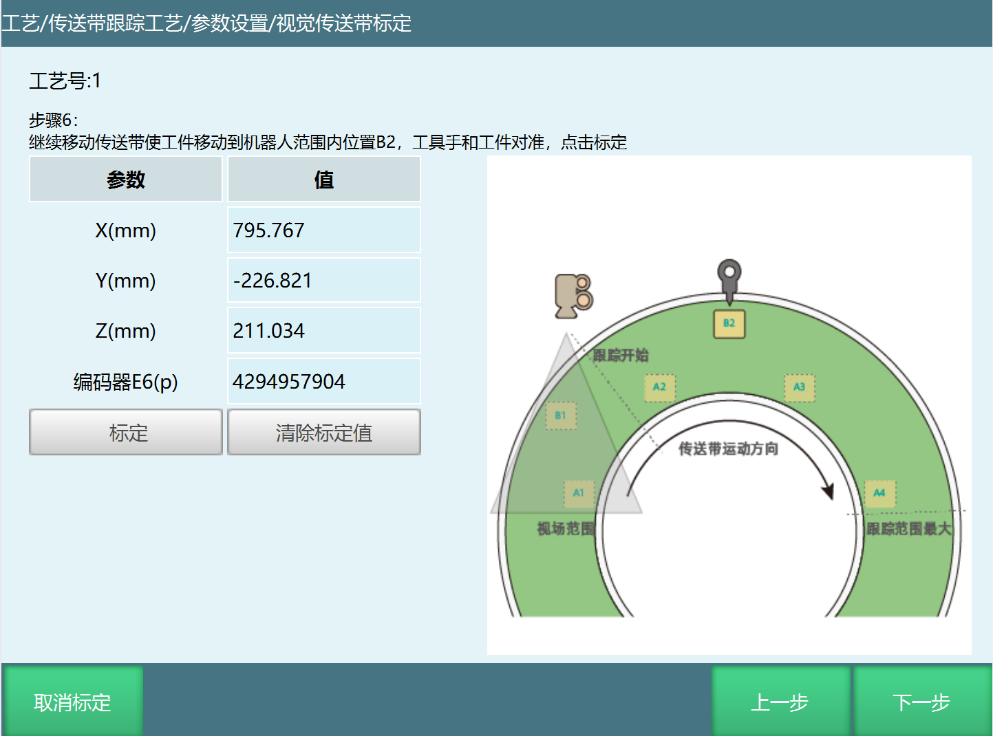
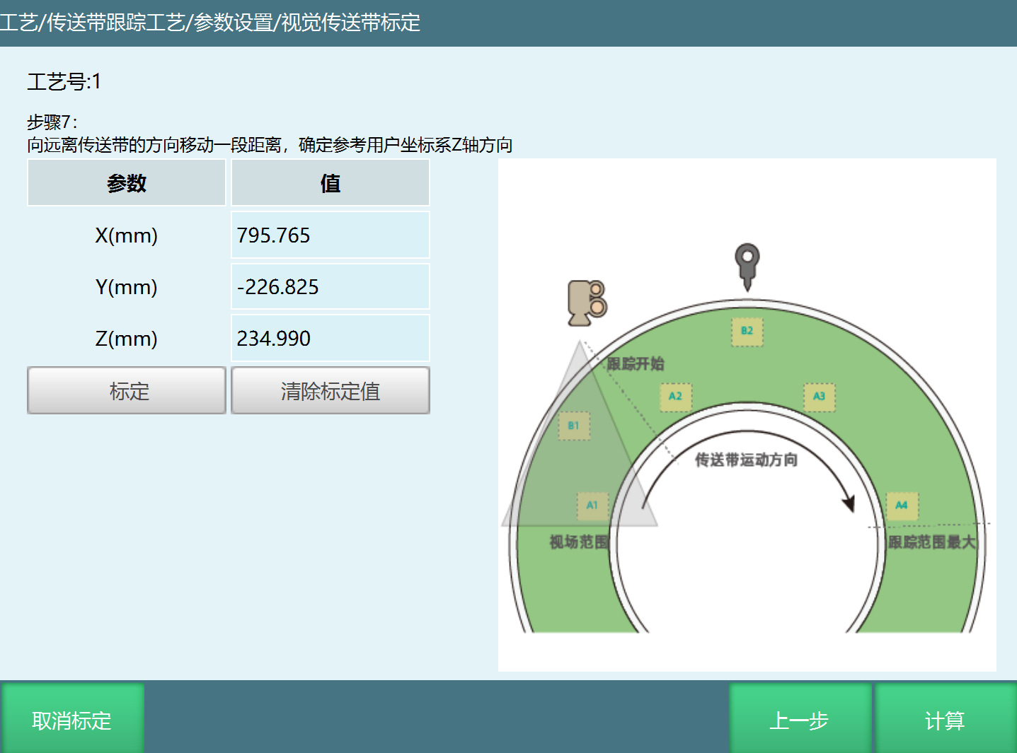
Step 1: Place the workpiece at position A1 in the camera's field of view, near one side edge of the conveyor belt, click calibrate.
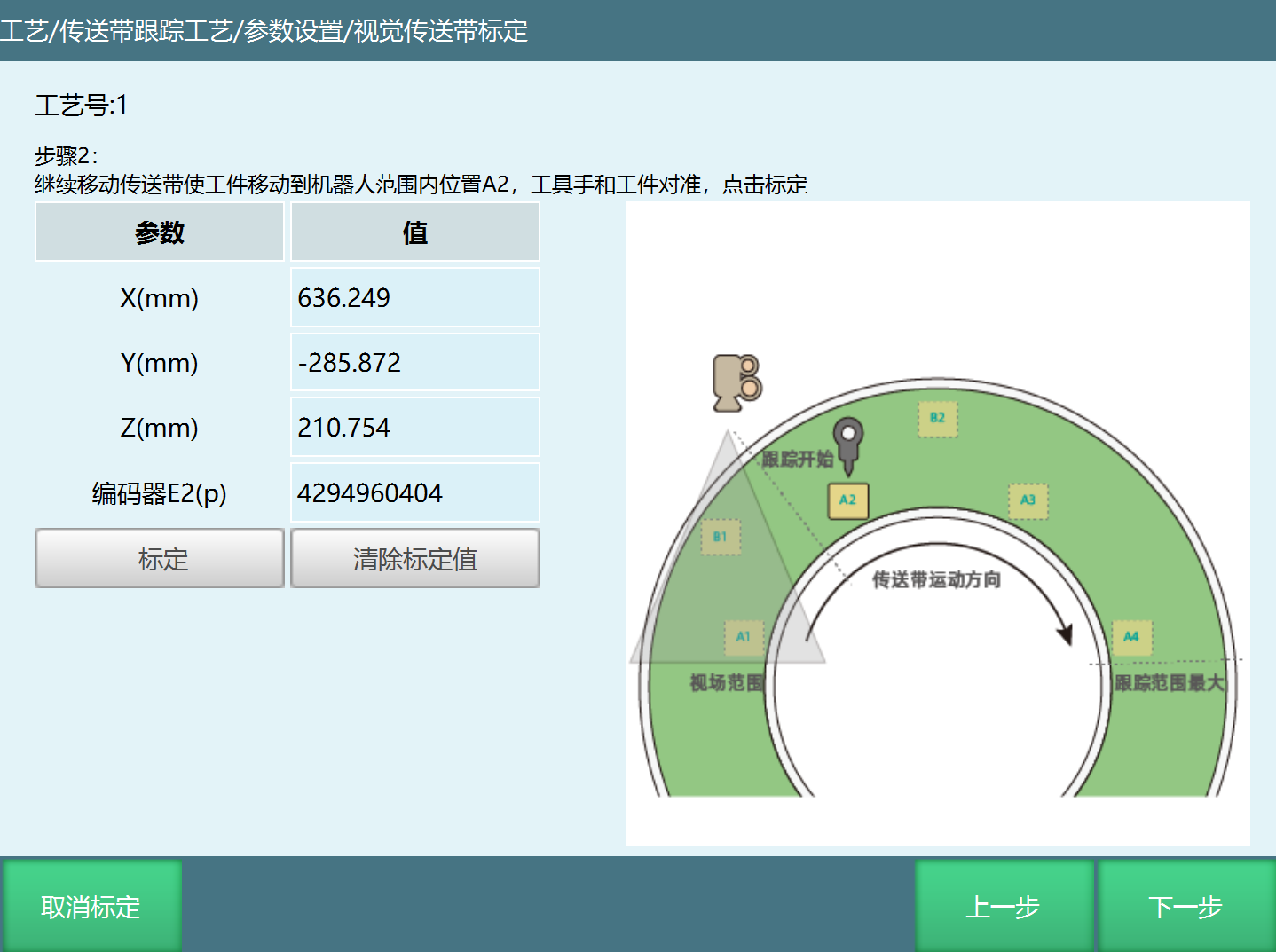
Step 2: Continue moving the conveyor belt to move the workpiece to position A2 within the robot range. Align the tool hand with the workpiece, click calibrate.
Step 3: Open the conveyor belt again to move the workpiece a distance to A3 (still within robot range). Align the tool hand with the workpiece, click calibrate.
Step 4: Open the conveyor belt again to move the workpiece a distance to A4 (still within robot range). Align the tool hand with the workpiece, click calibrate.
Step 5: Re-place the workpiece in the camera's field of view, near the other side edge B1 of the conveyor belt (different from step 1), click calibrate.
Step 6: Continue moving the conveyor belt to move the workpiece to position B2 within the robot range. Align the tool hand with the workpiece, click calibrate.
Step 7: Move a distance away from the conveyor belt to determine the reference user coordinate system Z axis direction.
Linear Conveyor Belt Sensor Calibration
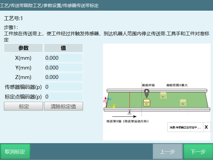
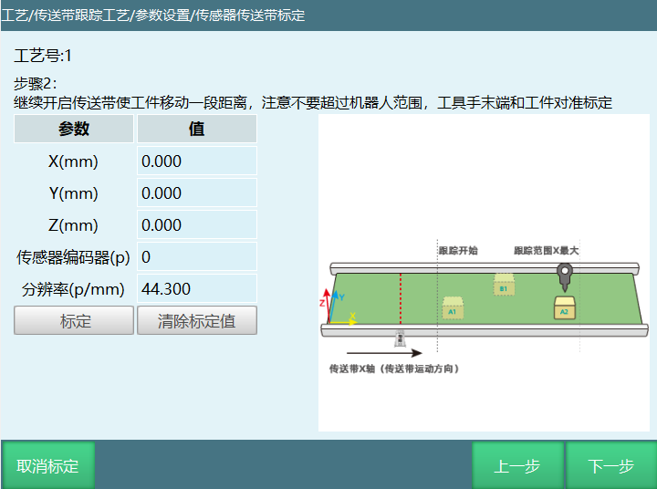
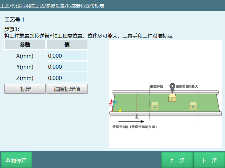
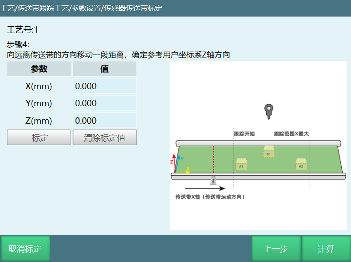
Step 1: Place workpiece on conveyor belt, make workpiece pass and trigger sensor. When reaching robot range, stop moving the conveyor belt. Align tool hand with workpiece and calibrate.
Step 2: Continue opening the conveyor belt to move the workpiece a distance. Be careful not to exceed robot range. Align tool hand end with workpiece and calibrate.
Step 3: Place workpiece at any position within robot range on the conveyor belt Y axis. The displacement should be as large as possible. Align tool hand with workpiece and calibrate.
Step 4: Move a distance away from the conveyor belt to determine the reference user coordinate system Z axis direction.
Step 5: After the above steps are completed, click calculate.
Circular Conveyor Belt Sensor Calibration
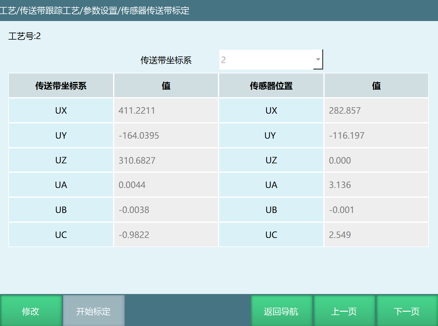
When workpiece identification method selects sensor, the sensor needs to be calibrated in this interface. Click [Modify] - [Start Calibration] button to enter the calibration interface, as shown below.
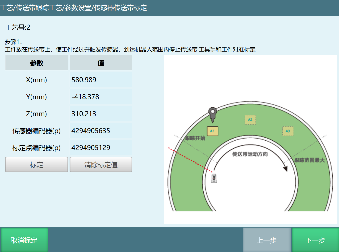
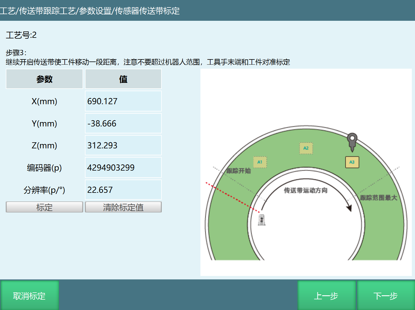
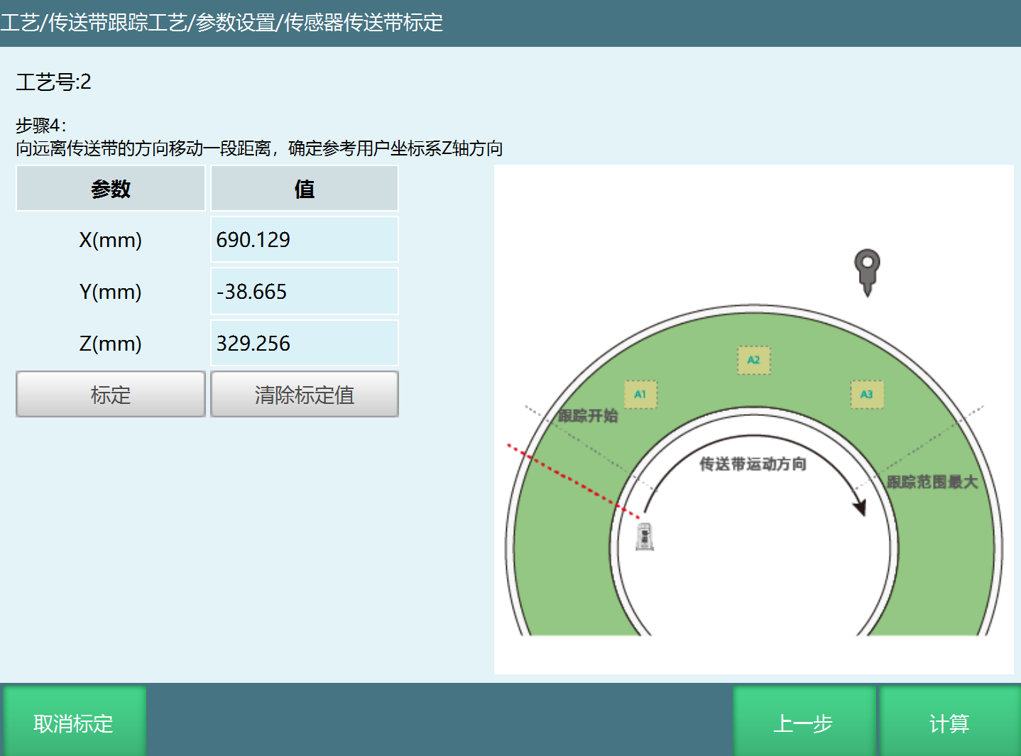
Step 1: Place workpiece on conveyor belt, make workpiece pass and trigger sensor. When reaching robot range, stop the conveyor belt. Align tool hand with workpiece and calibrate.
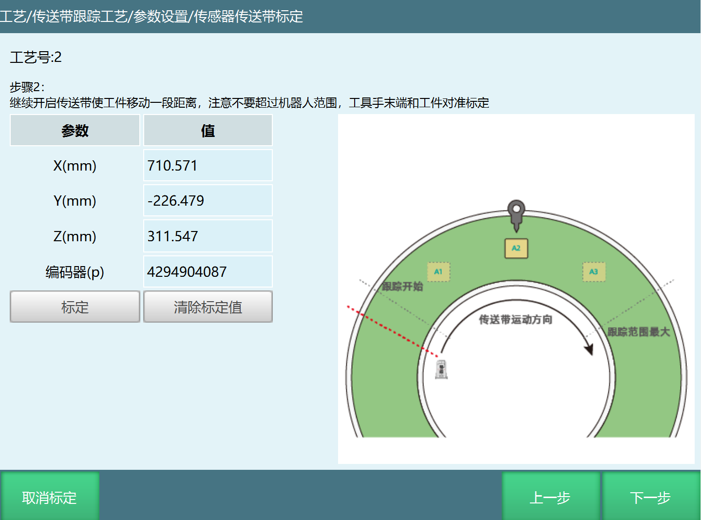
Step 2: Continue opening the conveyor belt to move the workpiece a distance. Be careful not to exceed robot range. Align tool hand end with workpiece and calibrate.
Step 3: Continue opening the conveyor belt to move the workpiece a distance. Be careful not to exceed robot range. Align tool hand end with workpiece and calibrate.
Step 4: Move a distance away from the conveyor belt to determine the reference user coordinate system Z axis direction.
Modbus Conveyor Belt Calibration
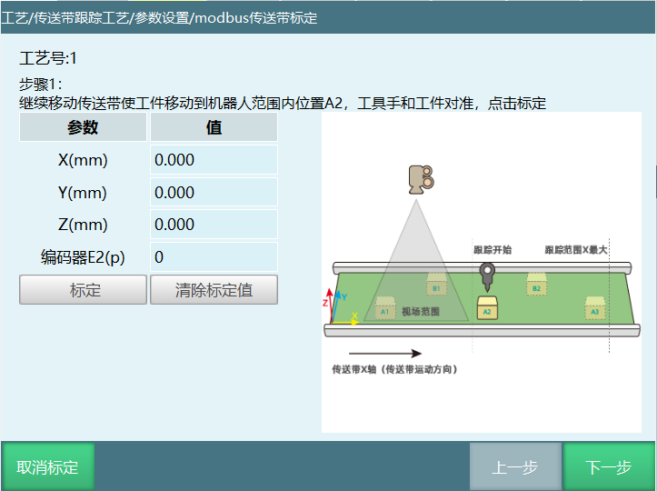
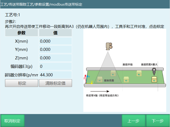
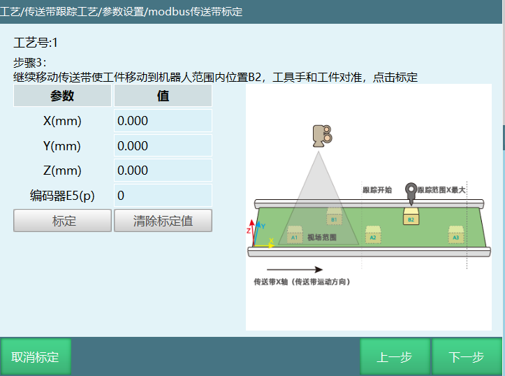
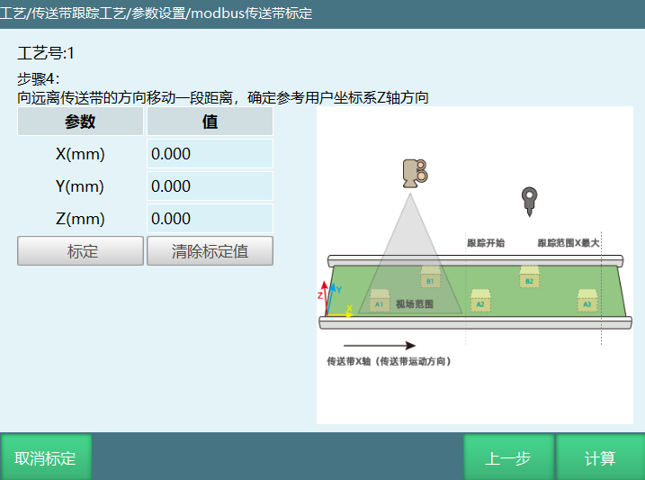
Step 1: Move the conveyor belt to move the workpiece to position A2 within the robot range. Align the tool hand with the workpiece, click calibrate.
Step 2: Open the conveyor belt again to move the workpiece a distance to A3 (still within robot range). Align the tool hand with the workpiece, click calibrate.
Step 3: Continue moving the conveyor belt to move the workpiece to position B2 within the robot range. Align the tool hand with the workpiece, click calibrate.
Step 4: Move a distance away from the conveyor belt to determine the reference user coordinate system Z axis direction, click calibrate.
Step 5: After the above steps are completed, click calculate.
Linear Conveyor Belt Tracking Range Setting
This interface is used to set some key positions and tracking ranges during the robot's tracking process, as shown below.
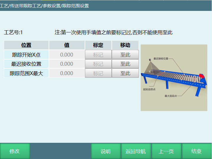
Note: Use the user coordinate system calibrated by the conveyor belt for calibration.
- Tracking Start X Point
This parameter only records the value of the conveyor belt coordinate X axis (conveyor belt running direction). During each tracking, only when the workpiece exceeds this position will the robot perform tracking.
- Latest Receive Position
The latest receive position of the workpiece on the conveyor belt X axis (conveyor belt running direction). If the workpiece exceeds this position before being tracked, the robot will not track the workpiece.
Note: If the calibrated range is found to be unreasonable, please reconfirm the user coordinate system calibration and check whether the selected user coordinate system direction is reasonable.
- Tracking Range X Maximum
The maximum position of the tracking range on the conveyor belt X axis (conveyor belt running direction). Regardless of whether the workpiece is being tracked, once it exceeds this position, the robot will abandon tracking and give a warning.
Circular Conveyor Belt Tracking Range Setting
This interface is used to set some key positions and tracking ranges during the robot's tracking process, as shown below.
Note: Use the user coordinate system calibrated by the conveyor belt for calibration.
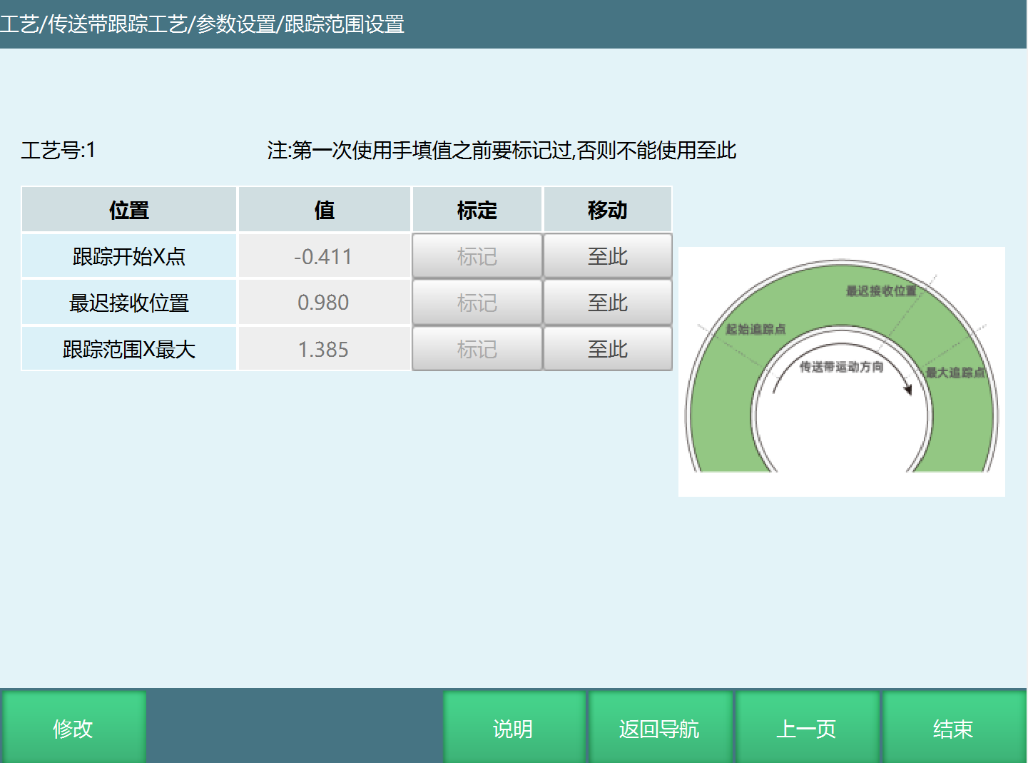
- Tracking Start X Point
When the workpiece on the conveyor belt moves to this coordinate position with the conveyor belt, the robot controller receives the signal, starts calculating and executes the chasing action, switching from static state to conveyor belt synchronous running state.
- Latest Receive Position
If the workpiece exceeds this position before being tracked, the robot will not track the workpiece.
- Tracking Range X Maximum
The maximum position of the tracking range on the conveyor belt X. Regardless of whether the workpiece is being tracked, once it exceeds this position, the robot will abandon tracking and give a warning.
Note: If the calibrated range is found to be unreasonable, please reconfirm the user coordinate system calibration and check whether the selected user coordinate system direction is reasonable.
Advanced Parameters
Synchronization Parameters
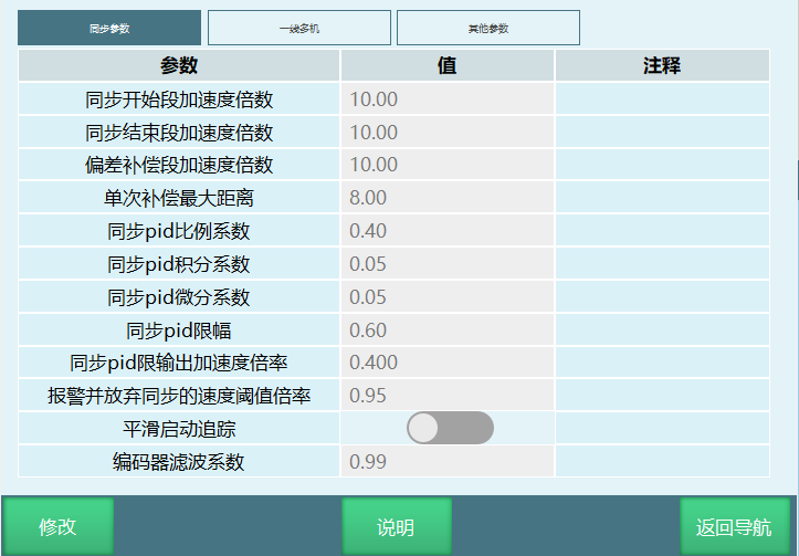
- Synchronization Start Segment Acceleration Multiplier
The maximum speed (max_vel) of the start tracking segment is calculated based on the conveyor belt speed, while the maximum acceleration (max_acc) is obtained by multiplying max_vel by this multiplier parameter, default 20 times. This parameter directly affects the speed of reaching synchronization, recommended range is 10~20. Too slow leads to slow tracking rhythm, too fast easily leads to jitter or overload.
- Synchronization End Segment Acceleration Multiplier
Used to calculate the maximum deceleration of the tracking stop segment. Calculation method is robot speed at stop time multiplied by this multiplier parameter, default 20 times. This parameter directly affects the length of the stop segment, recommended range is 10~20, default 20 times.
- Deviation Compensation Segment Acceleration Multiplier
Used for acceleration calculation of real-time deviation compensation during encoder speed mode synchronization. Calculation method is conveyor belt speed multiplied by this multiplier parameter.
- Single Compensation Maximum Distance
Used for real-time deviation compensation distance during encoder speed mode synchronization. Preventing single compensation distance from being too large which may cause: 1) instantaneous speed limit exceeded after superposition; 2) collision compensation for abnormal deviation.
- Synchronization PID Proportionality Coefficient
Applied to position PID adjustment in encoder position mode synchronization. Default 0.4, recommended range 0.1~1. When following synchronization cannot catch up with the workpiece and lag distance increases, increase this parameter; when synchronization around target position in conveyor belt movement direction is sometimes fast sometimes slow, decrease this parameter.
- Synchronization PID Integration Coefficient
Applied to position PID adjustment in encoder position mode synchronization, corrects accumulated error. Default 0.05.
a. If real-time deviation fluctuates slightly around 0 (mostly within 0.1mm), the parameter is normal;
b. If real-time deviation always fluctuates slightly at a fixed value, it indicates accumulated error, then increase the integration coefficient;
c. If real-time deviation fluctuates periodically around 0, then decrease the integration coefficient.
- Synchronization PID Differentiation Coefficient
Applied to position PID adjustment in encoder position mode synchronization. Default 0.05, recommended not to modify randomly. If encountering synchronization vibration, can set to 0.
- Synchronization PID Limit
Applied to output limit of position PID adjuster in encoder position mode synchronization, preventing single adjustment from being too large.
- Synchronization PID Output Acceleration Multiplier Rate
Applied to output smoothing of position PID adjuster in encoder position mode synchronization, preventing current impact caused by sudden acceleration changes.
- Alarm and Abandon Synchronization Speed Threshold Rate
Applied to tracking speed safety protection. If during tracking synchronization, the superimposed axis speed reaches the maximum speed threshold in joint parameters, alarm and abandon this synchronization, but the job program does not stop and continues.
Note: If this alarm occurs occasionally, it can continue running. If frequency is high, consider reducing synchronization tracking instruction speed parameters or synchronization acceleration multiplier.
- Smooth Start Tracking
Default closed. If opened, the tracking start motion will smoothly connect with the previous motion.
- Encoder Filter Coefficient
Low-pass filter coefficient for encoder values. The larger the value, the lower the filtering capability. Default 0.99.
Other Parameters
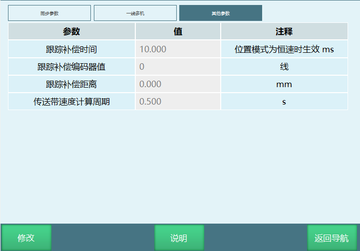
- Tracking Compensation Time
Used for compensation in the following situations:
a. Workpiece movement distance calculation compensation during sensor calibration in constant speed mode.
b. Workpiece displacement calculation compensation during synchronous tracking in encoder position/speed/constant speed modes.
c. In one-line multi-machine tracking, when the front machine virtual camera assigns workpiece to the back machine, it needs to convert the current workpiece robot coordinates to camera coordinate system coordinates, current workpiece robot coordinate calculation compensation.
- Tracking Compensation Encoder Value
Used for compensation in the following situations:
a. Workpiece displacement calculation compensation during synchronous tracking in encoder position/speed/constant speed modes.
b. In one-line multi-machine tracking, when the front machine virtual camera assigns workpiece to the back machine, it needs to convert the current workpiece robot coordinates to camera coordinate system coordinates, current workpiece robot coordinate calculation compensation.
c. In vision position debugging, offset position calculation compensation.
- Tracking Compensation Distance
Used for compensation in the following situations:
a. Workpiece displacement calculation compensation during synchronous tracking in encoder position/speed/constant speed modes.
b. In one-line multi-machine tracking, when the front machine virtual camera assigns workpiece to the back machine, it needs to convert the current workpiece robot coordinates to camera coordinate system coordinates, current workpiece robot coordinate calculation compensation.
c. In vision position debugging, offset position calculation compensation.
- Conveyor Belt Speed Calculation Cycle
Conveyor belt speed calculation method: Read encoder value once every time cycle (this parameter), then calculate the distance d the conveyor belt has moved through the encoder value change and calibrated resolution, finally divide distance d by time to get conveyor belt speed. Additionally, sliding average filtering is added.
The smaller the cycle, the larger the calculation result fluctuation, the more accurate the response to conveyor belt speed changes; conversely, the smaller the calculation result fluctuation, the more delayed the response to conveyor belt speed changes.
One-Line Multi-Machine
One vision, one conveyor belt, two or more robots collaborative tracking and grasping
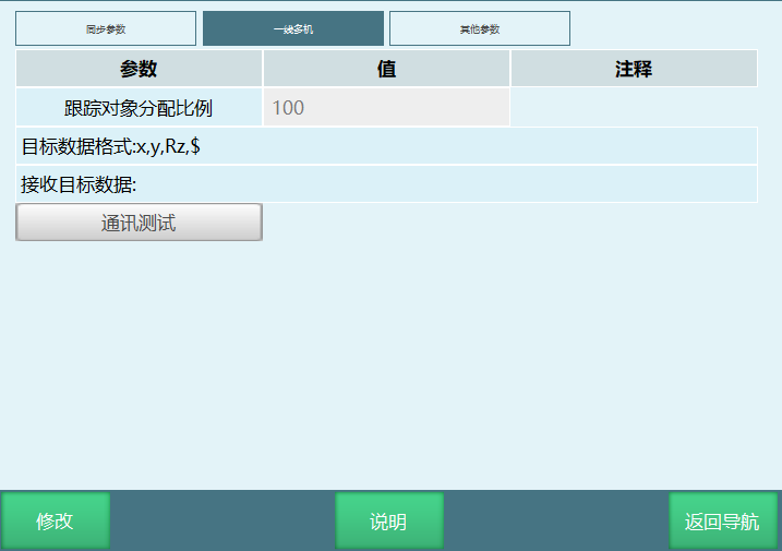
- Tracking Object Allocation Ratio:
If the robot's ratio value is less than 100%, it means this machine is not the last machine, and will automatically start a virtual camera server (a separate module, IP is the local machine address, port is current vision process number +3000), for the robot's vision process to connect and send object coordinates. Data format is the default multi-target data format.
The necessity of this parameter: In multi-machine collaborative tracking palletizing and boxing production lines, if the incoming material line and boxing line have the same direction, it must ensure that the last robot has sufficient incoming material, so that its box is filled first and flows away. If not allocated by ratio, it may cause the front robot's box to be filled first, but because the back box is not filled, it blocks the production line. If other scenarios don't need this, the default ratio 100% is fine.
Target Data Format: This column displays the received data sent by the vision side. The format is related to the connection parameter settings in the vision process - parameter settings interface. The displayed data format changes according to the connection parameter changes.
Communication Test Button: Test whether the communication between this machine and the previous robot (or camera) is normal.
Receive Target Data: After communication test, display the received data sent by the vision side.
Conveyor Belt Instructions
CONVEYOR_ON - Start Conveyor Belt Tracking
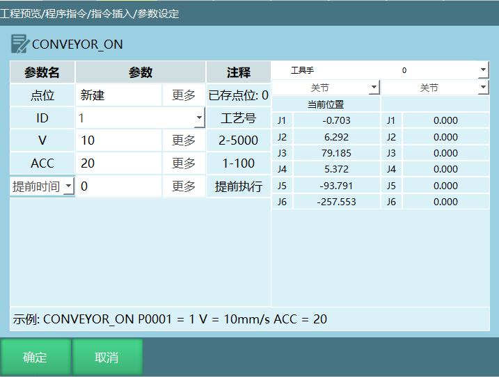
Format: CONVEYOR_ON [Instruction Name] P/GP/Workpiece Point [Point Position] ID [Tracking End Process Number] V [Tracking Speed] ACC [Acceleration].
Function: Start tracking after the workpiece reaches the tracking range.
Parameters:
| Parameter | Description |
|---|---|
| Point Position | Reference point position data (P point, GP point, Workpiece point: point sent by camera) Workpiece point: When the camera sends a trajectory, the first point of this trajectory is used as the workpiece point P/GP: Users can choose an existing position variable or create a new position variable. This point is the reference point during conveyor belt tracking, and can also determine the tracking height. It is recommended to set this point to the middle point of the workpiece to be tracked. If you need to run a trajectory on the workpiece, set this point to the first point of the trajectory |
| ID | Conveyor belt tracking process number |
| V | Speed during conveyor belt tracking |
| ACC | Acceleration during conveyor belt tracking |
| Pre-time | Execute non-motion instructions early, unit ms Description: Setting early execution of 3 seconds means the next non-motion instruction executes 3 seconds early. |
| Pre-distance | Robot moves to the set pre-distance to execute the next non-motion instruction, unit mm Description: Pre-distance set to 10mm, assuming the entire trajectory is robot P1 to P2, total trajectory is 100mm, then when the robot moves to 90mm, it will sequentially execute the following non-motion instructions. |
| Pre-progress | Robot moves to the set pre-progress to execute the next non-motion instruction, unit % Description: Pre-progress set to 10%, assuming the entire trajectory is robot P1 to P2, total trajectory is 100mm, then pre-progress 10%, when the robot moves to [100-100*10%] mm, it will sequentially execute the following non-motion instructions |
CONVEYOR_OFF - End Conveyor Belt Tracking
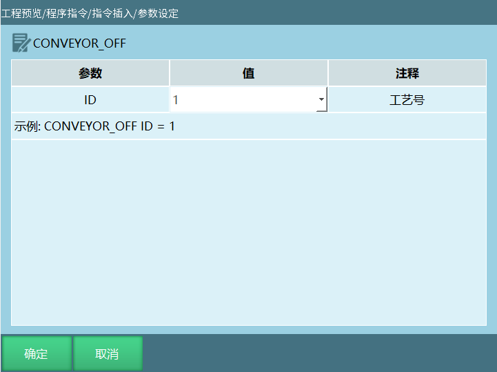
Format: CONVEYOR_OFF [Instruction Name] ID [Tracking End Process Number]
Function: End conveyor belt tracking.
Parameters:
| Parameter | Description |
|---|---|
| ID | Conveyor belt tracking process number |
CONVEYOR_POS - Get Conveyor Belt Tracking Position
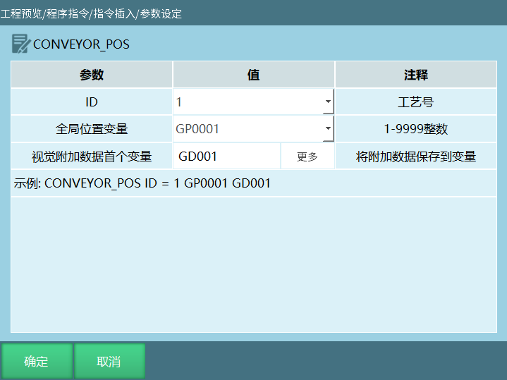
Format: CONVEYOR_POS [Instruction Name] ID [Process Number].
Function: Store the sensor calibration result into the selected position variable, and store the additional data value into the numeric variable.
Parameters:
| Parameter | Description |
|---|---|
| ID | Conveyor belt tracking process number |
| Global Position Variable | When sensor triggers, store sensor calibration result into GP point When vision triggers, store each vision photo position into GP point |
| Additional Data First Variable | Store additional data value into variable, variable type (integer, floating-point, string) Set additional data count in vision process - vision parameter interface. Set additional data first variable in get conveyor belt tracking position parameter interface. Execute this instruction to store the obtained additional data values into variables. Users can use conditional judgment to call corresponding variables to grasp workpieces of different colors, shapes, etc. For example: additional data first variable is GD001, additional data count is 2. Execute this instruction will store user-defined additional data values sequentially into GD001, GD002. If users need to grasp workpieces of different colors on the conveyor belt and place them at different positions, we can represent workpieces of different colors with different variable values, then use IF conditional judgment to select corresponding variables to grasp workpieces of different colors. Assuming red workpiece is represented by GD001=1, when the camera captures a red workpiece, conditional judgment if GD001=1, grasp red workpiece |
CONVEYOR_REMOVE - Delete Conveyor Belt Tracking Target
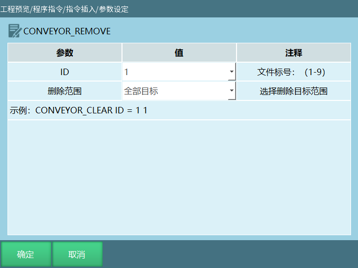
Format: CONVEYOR_REMOVE [Instruction Name] ID=1 [Tracking Process Number] Delete Range [All Targets, This Target].
Function: Delete tracking signal according to the selected delete range.
Parameters:
| Parameter | Description |
|---|---|
| ID | Conveyor belt tracking process number, range [1,9] |
| Delete Range | All Targets: When program runs and gives conveyor belt tracking start signal multiple times, all signals except the first one will be deleted This Target: When program runs and gives conveyor belt tracking start signal multiple times, each cycle will delete the previous signal Assume there are 5 workpieces, workpiece 1 tracks, workpiece 2 tracking signal deleted does not track, workpiece 3 tracks, workpiece 4 tracking signal deleted does not track, workpiece 5 tracks |
CONVEYOR_CHECKEND - End Conveyor Belt Workpiece Detection
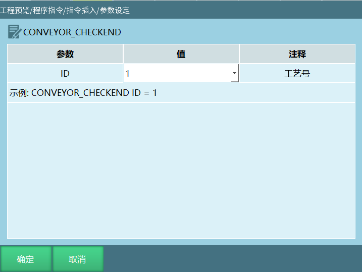
Format: CONVEYOR_CHECKEND [Instruction Name] ID [Tracking Process Number].
Function: Stop detecting workpieces. After executing this instruction, even if workpieces pass the sensor, they will not participate in queue calculation.
Parameters:
| Parameter | Description |
|---|---|
| ID | Conveyor belt tracking process number |
CONVEYOR_CHECKPOS - Start Conveyor Belt Workpiece Detection
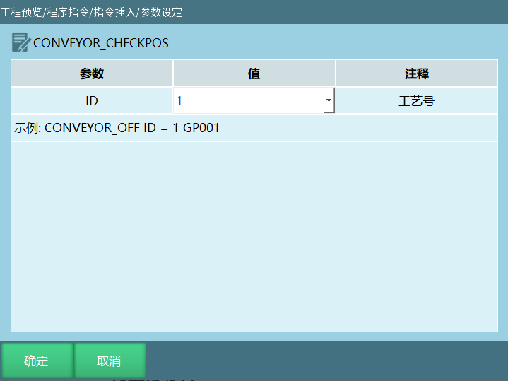
Format: CONVEYOR_CHECKPOS [Instruction Name] ID [Tracking Process Number].
Function: Execute this instruction, when workpieces pass the sensor, they will participate in queue calculation.
Parameters:
| Parameter | Description |
|---|---|
| ID | Conveyor belt tracking process number |
CONVEYORWAIT - Conveyor Belt Wait for Material
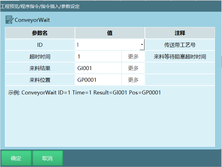
Format: CONVEYORWAIT [Instruction Name] ID [Tracking Process Number] Timeout [Incoming Material Blocking Timeout] Incoming Result [Position Variable] Incoming Position [Position Variable]
Function: Block and wait for T time. If there is a workpiece and the workpiece is in the catchable area, then end; if timeout, then end; if T=0, then block and wait indefinitely for the workpiece to enter the catchable area.
Parameters:
| Parameter | Description |
|---|---|
| ID | Conveyor belt tracking process number |
| Timeout | Block and wait for T time. If there is a workpiece and the workpiece is in the catchable area, then end; if timeout, then end; if T=0, then block and wait indefinitely for the workpiece to enter the catchable area. |
| Incoming Result | Incoming result is that the signal was triggered within the time range, the variable will be set to workpiece status: 0--no workpiece; 1--has workpiece but not entered catchable area; 2--workpiece in catchable area; 3--workpiece has exceeded catchable area |
| Incoming Position | Incoming position is the initial position and stored in variable |
CONVEYSETOBJPOSITION - Set Conveyor Belt Object Position
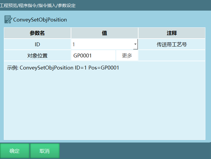
Format: CONVEYSETOBJPOSITION [Instruction Name] ID [Tracking Process Number] Object Position [Position Variable]
Function: Object position is the conveyor belt tracking position after offset (the point position with offset value calculated and set into the conveyor belt tracking queue)
Parameters:
| Parameter | Description |
|---|---|
| ID | Conveyor belt tracking process number |
| Object Position | Object position is the conveyor belt tracking position after offset (the point position with offset value calculated and set into the conveyor belt tracking queue) |
Program Example Description
Example 1: Sensor Trigger, Run Trajectory on Tracked Workpiece
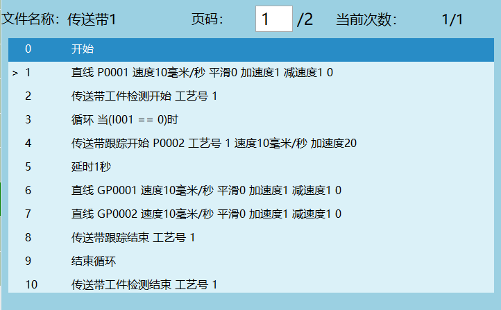
Example Description:
Robot safety position;
Start detecting workpieces, when workpiece passes sensor it starts participating in queue calculation;
Loop start, workpiece loop tracking;
Start tracking workpiece;
Delay 1 second;
Run linear trajectory on tracked workpiece (GP0001-GP0002);
End workpiece tracking;
Workpiece loop tracking end;
Stop detection, workpiece passing conveyor belt again will not participate in queue calculation.
Example 2: Sensor Trigger, Use External Point Function to Run Trajectory
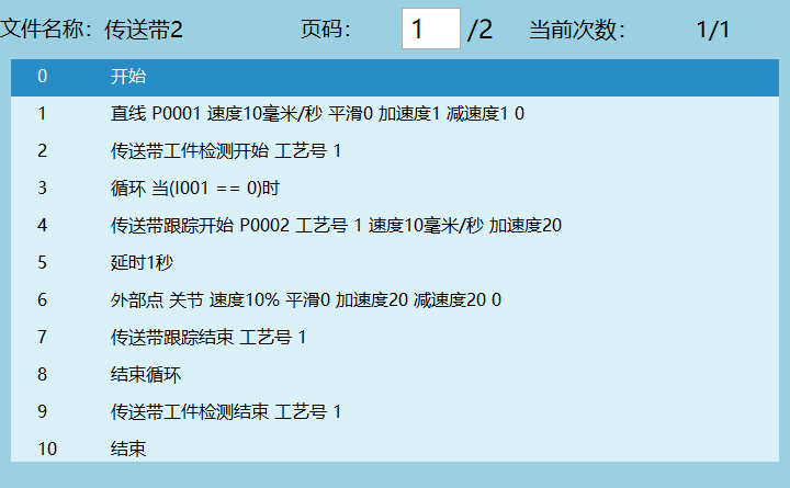
Example Description:
Robot safety position;
Start detecting workpieces, when workpiece passes sensor it starts participating in queue calculation;
Loop start, workpiece loop tracking;
Start tracking workpiece;
Delay 1 second;
Use external point function to send points and run trajectory;
End workpiece tracking;
Workpiece loop tracking end;
Stop detection, workpiece passing conveyor belt again will not participate in queue calculation.
Example 3: Vision + Conveyor Belt Tracking
Track workpieces through vision. Select vision for the workpiece detection signal source.
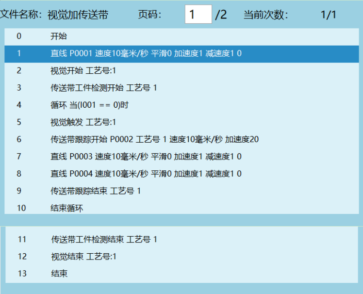
Example Description:
Robot safety position;
Open vision;
Conveyor belt workpiece detection start;
Loop start, workpiece loop tracking;
Camera takes one photo, vision triggers once (when the trigger condition selected in vision software is continuous, the vision trigger instruction triggers once and the workpiece can still be tracked normally; when trigger condition is single, the camera takes one photo and triggers once);
Start tracking workpiece;
Track trajectory (P0003-P0004);
End workpiece tracking;
Workpiece loop tracking end;
Stop detection, workpiece passing conveyor belt again will not participate in queue calculation;
Close vision.
Example 4: Conveyor Belt Combined with Palletizing
Vision tracks workpieces, palletize the grasped workpieces.
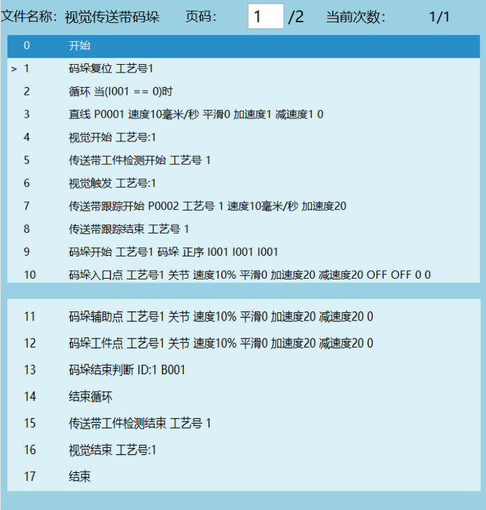
Example 5: Get Tracking Position Additional Data Parameter Description
- Vision process - vision parameter interface set additional data count, maximum supports 10.
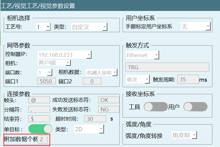
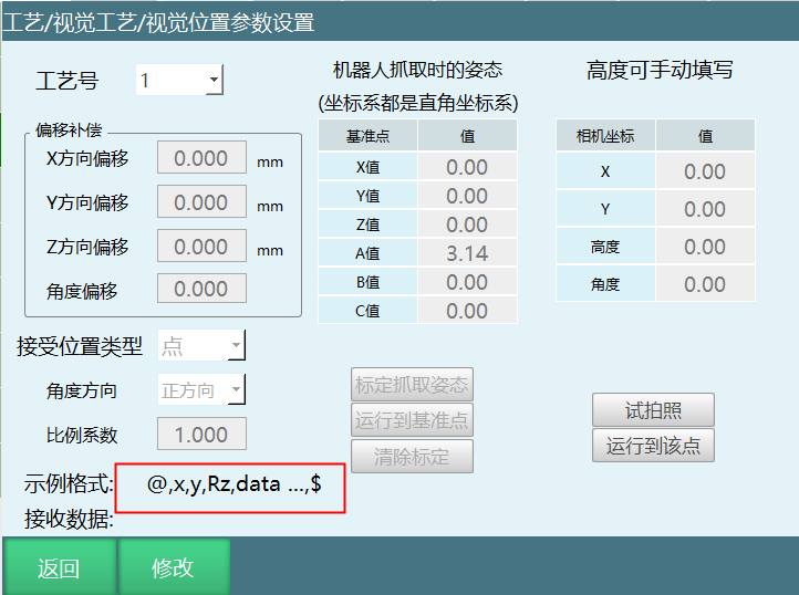
- Click vision position parameter to enter parameter interface and view example format changes, "data" represents additional data.
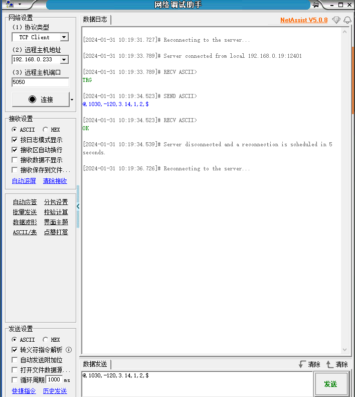
- External device: network debugging assistant, send positions according to the example format in vision position parameter interface.
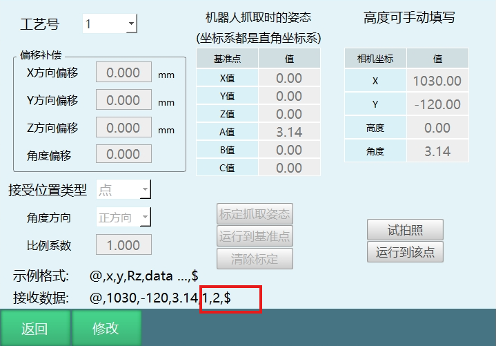
- Click test photo, after network assistant sends positions, the "1,2" in received data row represents additional data. Additional data defaults to store in GS001, stored sequentially according to defined additional data count.
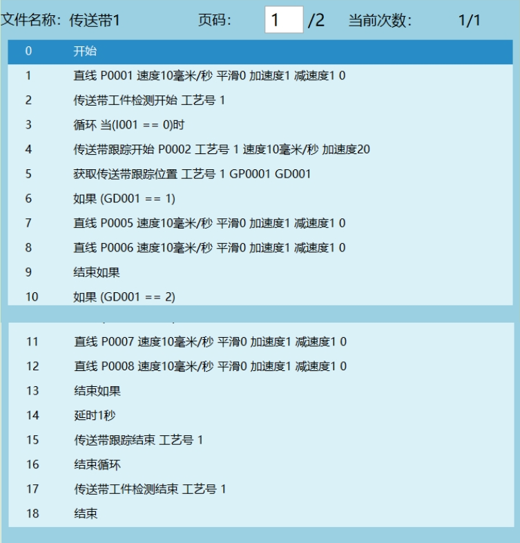
- If inserting get conveyor belt tracking position instruction, executing the instruction will store the defined additional data values into the user's selected variables (integer, floating-point, string). Users can represent workpiece shape and color with numbers (for example GD001=1 represents red, GD002=2 represents green), then through conditional judgment track and grasp workpieces of different colors.
Example:
Q&A for Retrieval
Q: What is conveyor belt tracking process?
A: Conveyor belt tracking refers to the robot using the user-input material point position and the corresponding encoder value when the material is at this position to calculate the material point position in real-time, and track the material through motion.
Q: How to enter the conveyor belt tracking process parameter settings interface?
A: Click [Process] - [Conveyor Belt Tracking Process] - [Parameter Settings] to enter the conveyor belt tracking process parameter settings interface.
Q: What are the conveyor belt position modes?
A: Supports three modes: Select Encoder Value (normal conveyor belt calibration), Select Constant Speed Setting (manually fill in conveyor belt speed), Select Encoder Speed (use conveyor belt speed calculation after smooth filtering, no longer supports conveyor belt dynamic speed adjustment and dynamic synchronization).
Q: What might cause the encoder value to not be read successfully?
A: Generally divided into two situations: encoder interface wiring method is incorrect; encoder is connected to the wrong port position on the IO board. Port position on the IO board can refer to the corresponding IO board definition diagram; encoder port wiring method can refer to the corresponding encoder definition diagram.
Q: What are the encoder count maximum and minimum value ranges?
A: According to different versions: integrated drive version is 0-65535; Nuodajia firmware below version 18 is 0-1024; Nuodajia firmware version 18 is -2147483648-2147483647; R4C version is -2147483648-2147483647; 2200-A01 version is 0-4294967295.
Q: What tracking methods does conveyor belt tracking support?
A: Supports five tracking methods: Vision, Sensor, Sensor+Vision, Global Variable+Modbus, Global Variable+Vision.
Q: What are the sensor trigger methods?
A: IO rising edge and falling edge trigger. Rising edge refers to the edge trigger when IO signal changes from 0 to 1; falling edge refers to the edge trigger when IO signal changes from 1 to 0.
Q: What are the steps for linear conveyor belt vision calibration?
A: Total 7 steps: Step 1 place workpiece at camera field of view A1 position, click calibrate; Step 2 move conveyor belt to move workpiece to A2 position within robot range, align and calibrate; Step 3 move workpiece to A3 position, align and calibrate; Step 4 re-place workpiece at field of view B1 position, click calibrate; Step 5 move workpiece to B2 position, align and calibrate; Step 6 move away from conveyor belt to determine Z axis direction, click calibrate; Step 7 click calculate.
Q: What are the steps for circular conveyor belt vision calibration?
A: Total 7 steps: Step 1 place workpiece at camera field of view A1 position, click calibrate; Step 2 move conveyor belt to move workpiece to A2 position, align and calibrate; Step 3 move workpiece to A3 position, align and calibrate; Step 4 move workpiece to A4 position, align and calibrate; Step 5 re-place workpiece at field of view B1 position, click calibrate; Step 6 move workpiece to B2 position, align and calibrate; Step 7 move away from conveyor belt to determine Z axis direction.
Q: What are the steps for linear conveyor belt sensor calibration?
A: Total 5 steps: Step 1 workpiece triggers sensor and reaches robot range, align and calibrate; Step 2 move conveyor belt to move workpiece a distance, align and calibrate; Step 3 place workpiece at any position within robot range on conveyor belt Y axis, align and calibrate; Step 4 move away from conveyor belt to determine Z axis direction; Step 5 click calculate.
Q: What parameters are included in linear conveyor belt tracking range setting?
A: Includes three parameters: Tracking Start X Point (workpiece exceeds this position robot will track), Latest Receive Position (workpiece exceeds this position robot will not track), Tracking Range X Maximum (workpiece exceeds this position robot abandons tracking and warns).
Q: What is the function of synchronization start segment acceleration multiplier?
A: The maximum speed (max_vel) of the start tracking segment is calculated based on the conveyor belt speed, and the maximum acceleration (max_acc) is max_vel multiplied by this multiplier parameter, default 20 times. This parameter directly affects the speed of reaching synchronization, recommended range is 10~20.
Q: How to adjust the synchronization PID proportionality coefficient?
A: Default 0.4, recommended range 0.1~1. When following synchronization cannot catch up with the workpiece and lag distance increases, increase this parameter; when synchronization around target position in conveyor belt movement direction is sometimes fast sometimes slow, decrease this parameter.
Q: What are the functions and parameters of the CONVEYOR_ON instruction?
A: Function: Start tracking after workpiece reaches tracking range. Parameters include: Point Position (reference point position data), ID (process number), V (tracking speed), ACC (acceleration), Pre-time, Pre-distance, Pre-progress.
Q: What is one-line multi-machine mode?
A: One vision, one conveyor belt, two or more robots collaborative tracking and grasping. If the robot's ratio value is less than 100%, it means this machine is not the last machine, and will automatically start a virtual camera server.
Q: What is the process for Example 3 vision + conveyor belt tracking?
A: Process: Robot safety position → Open vision → Conveyor belt workpiece detection start → Loop start → Camera takes one photo → Start tracking workpiece → Track trajectory → End workpiece tracking → Loop end → Stop detection → Close vision.
Q: How to adjust the synchronization PID integration coefficient?
A: Default 0.05. If real-time deviation fluctuates slightly around 0 (mostly within 0.1mm), the parameter is normal; if real-time deviation always fluctuates slightly at a fixed value, it indicates accumulated error, then increase the integration coefficient; if real-time deviation fluctuates periodically around 0, then decrease the integration coefficient.
Q: How to set the encoder direction parameter?
A: Open the conveyor belt, observe whether the encoder value changes with the conveyor belt movement. If no change, the encoder is not recognized. If it changes with the conveyor belt movement, select the corresponding direction here. Encoder value increasing is forward, decreasing is reverse.
Version History
| Version | Date | Changes | Author |
|---|---|---|---|
| 1.0.0 | 2026-06-25 | Initial version | tongmengyuan123 |