DXF Function User Manual
Operation Flow
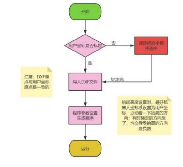
The DXF function is built on user coordinates. The origin of the user coordinate corresponds to the origin of the graphics in the DXF file.
The workpiece and DXF file must be reproduced at a 1:1 scale. The workpiece origin position must correspond to the graphics origin in the DXF file.
DXF files must be drawn using CAD software. Export the file in .dxf format (QCAD drawing software is recommended).
The DXF function supports reading lines, arcs, polylines, splines, and full circle entities. Other entities are not currently supported.
Please delete unnecessary graphics from the DXF file. Keep it as simple as possible, and try to make the graphic a single complete continuous trajectory. Other cluttered graphics or segmented drawings may affect the robot's motion trajectory.
Note: The origin and XY axes of the graphics in the DXF file are the origin and XY axes in the CAD software.
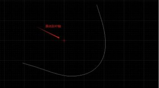
DXF Function
Graphic Interface
Operation path: [Process > DXF]
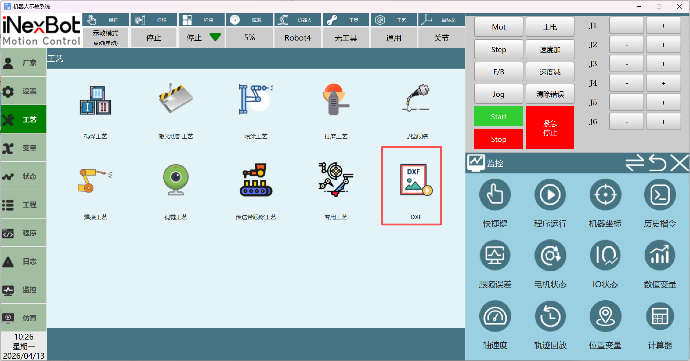
Click to enter DXF
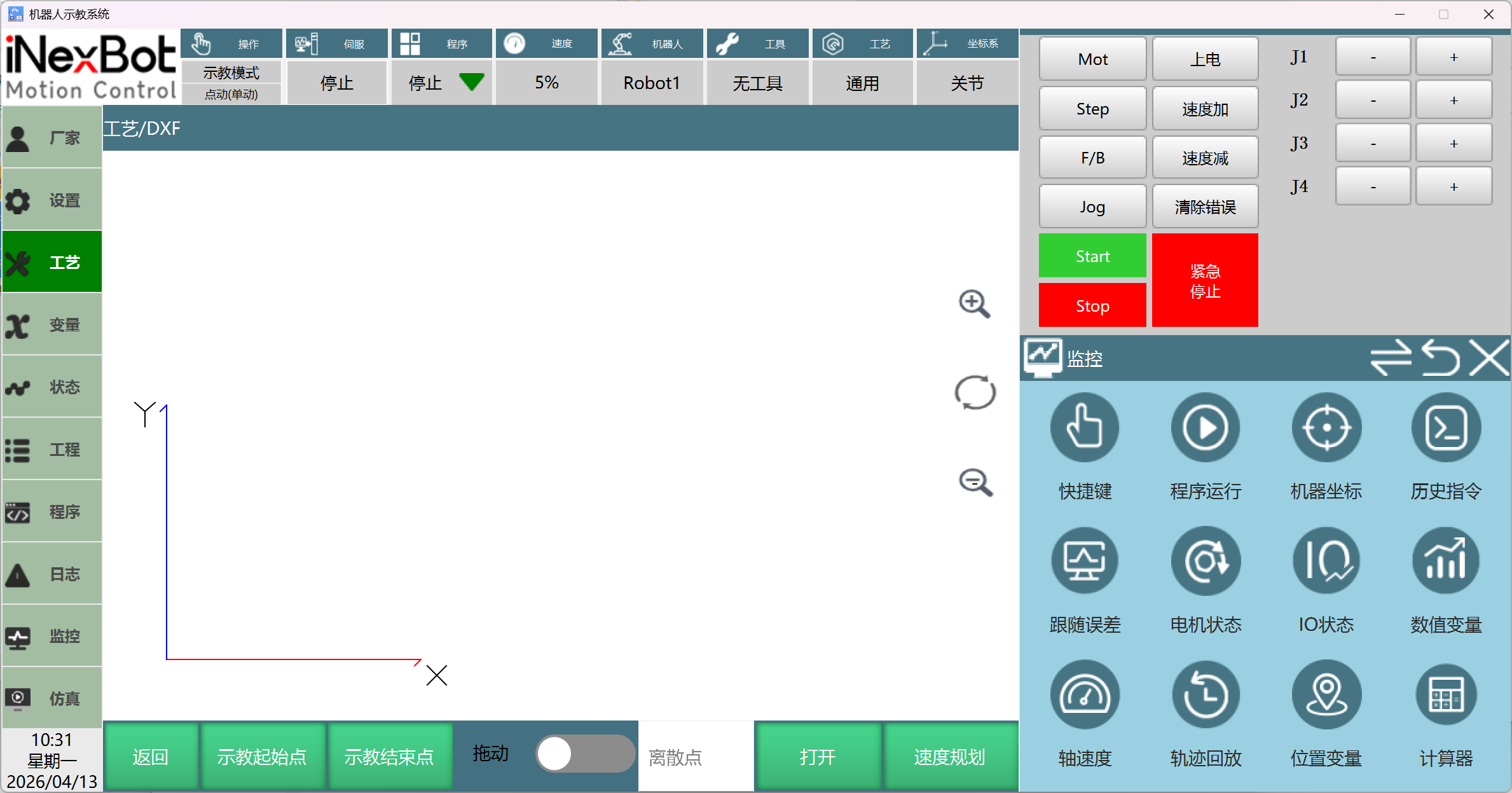
| Function | Description |
|---|---|
| Return | Returns to the [Process] interface. |
| Teach Start Point | When using external TCP, marks the workpiece start point for position calibration. |
| Teach End Point | When using external TCP, marks the workpiece end point for position calibration. |
| Drag | Toggle on to drag the canvas position. |
| Discrete Points | Before opening a DXF file (spline), fill in the discrete points value first. Higher values generate more points in the job file (except for splines, other supported entities do not require changing discrete points; use the default value as it has no effect on them). |
| Open | Requires inserting a USB drive. The default directory is the controller directory. Place the DXF file in the USB drive root directory. |
| Speed Planning | Used to plan the speed of trajectories in the drawing. |
 | Used to zoom in on the canvas. |
 | Used to zoom out the canvas. |
| Used to reset the canvas size. |
 | Used to reset the canvas position. |
Opening a DXF File
Old Version
RTL-25.01.0
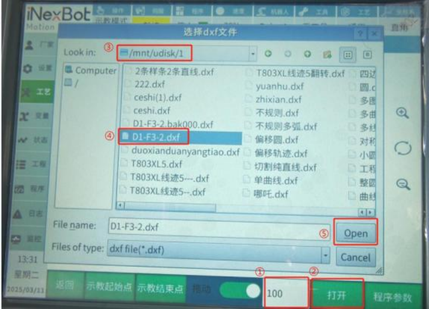
Steps: Insert USB drive into the teach pendant. ① Fill in the desired [Discrete Points] → ② Click [Open] → ③ Select the USB drive folder → ④ Select the corresponding DXF file → ⑤ Click [Open] to open the file.
Notes:
After opening a DXF file, if you change the discrete points, you must reload the DXF file for the changes to take effect.
Discrete points only apply to splines. Other supported entities generate point counts based on the points existing in the drawing.
The maximum supported discrete points value is currently 5000. Enter a reasonable value; excessive discrete points in small trajectories are not recommended.
When opening a DXF file, click Open until you reach the desired DXF file. Do not drag any folders during this process!
New Version
RTL-25.01.2
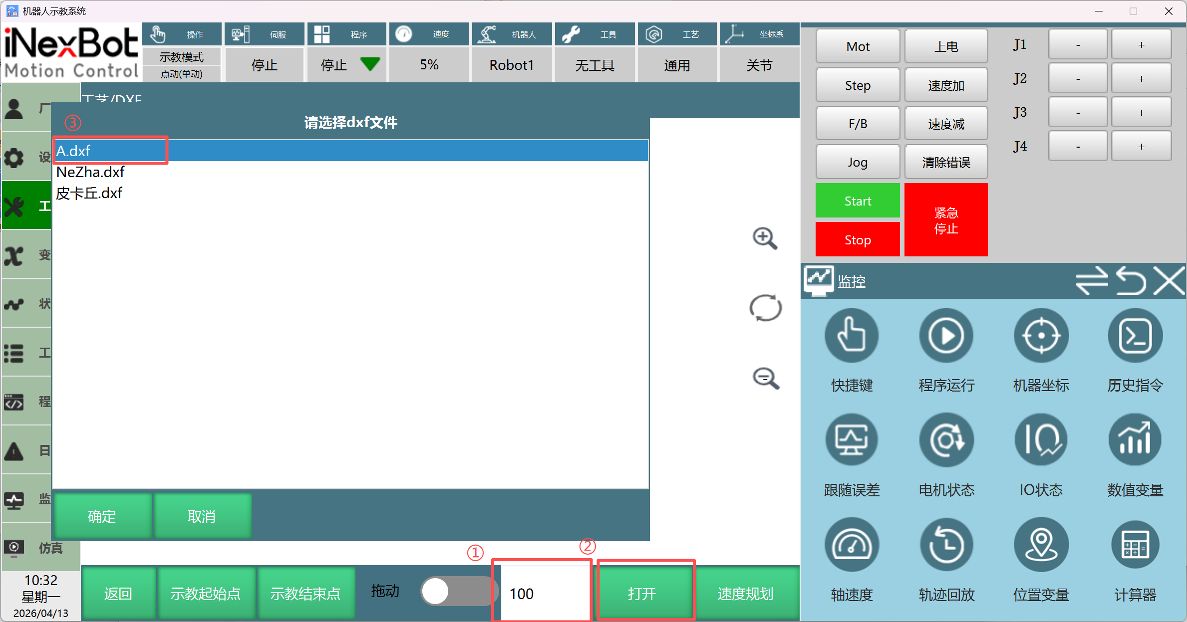
Steps: Insert USB drive into the teach pendant. ① Fill in the desired [Discrete Points] → ② Click [Open] → ③ Select the corresponding DXF file → ④ Click [OK] to open the file.
After opening, the preview appears as follows:
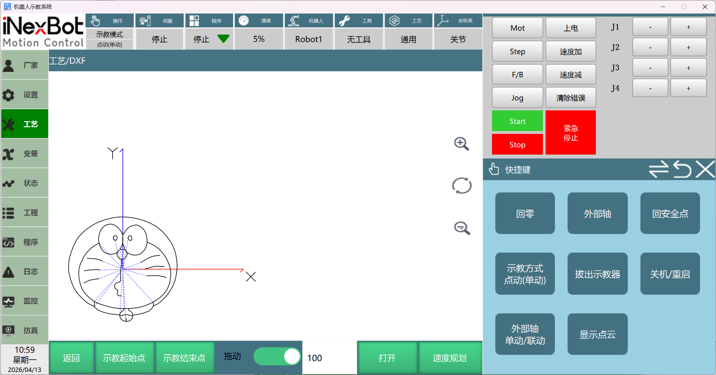
In the graphics, dashed lines connecting to the origin represent the starting point of each trajectory segment in the DXF file. X represents the positive X-axis direction, Y represents the positive Y-axis direction.
Speed Planning Parameter Interface
Operation path: [Process] > [DXF] > [Speed Planning]
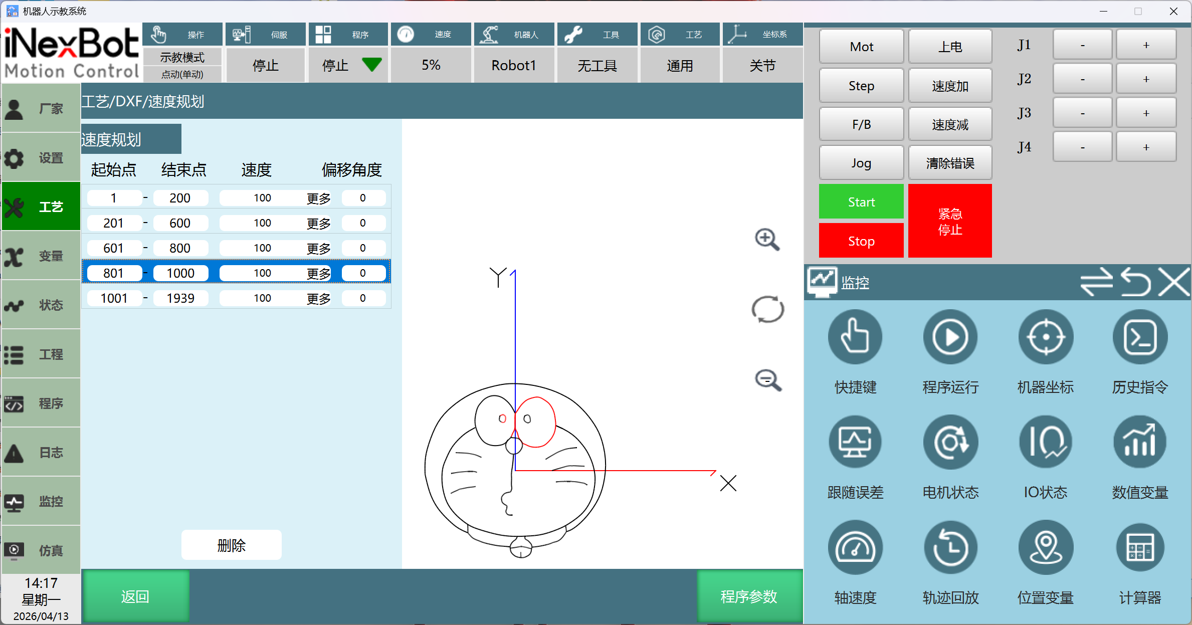
| Function | Description |
|---|---|
| Start Point | The starting point of a trajectory segment |
| End Point | The ending point of a trajectory segment |
| Speed | Cartesian speed for this trajectory segment |
| Offset Angle (external TCP only) | The offset angle relative to the external TCP tangential motion direction for this trajectory segment (gradual offset) |
| Delete | Deletes this point trajectory segment and merges it into the previous segment |
Notes:
By default, it spans from the first point to the last point of the entire trajectory. Modify the end point parameter to set partial trajectory segments; remaining points are automatically divided into new trajectory segments. When selected, the corresponding points are displayed as a red trajectory in the drawing.
These points already include lift points.
Program Parameter Interface
Operation path: [Process] > [DXF] > [Speed Planning] > [Program Parameters]
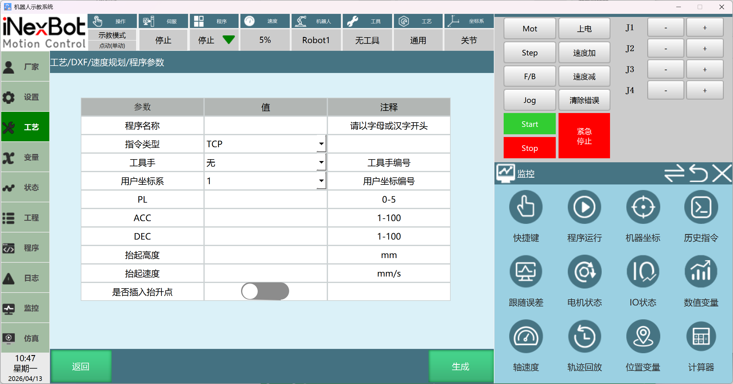
| Function | Description |
|---|---|
| Program Name | Job file name starting with a letter or Chinese character. |
| Instruction Type | Choose TCP or External TCP. |
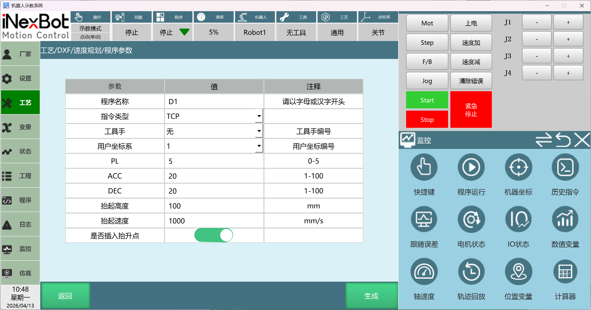
| Tool | Select the tool coordinate to use. (When a user mounts a tool on the robot end-effector, the tool center point often does not coincide with the robot flange center. In this case, tool coordinate calibration is required. Refer to INEXBOT's official robot calibration methods; this document does not cover this in detail. If the user does not perform tool calibration, the actual trajectory will deviate significantly from the imported graphic trajectory. The farther the tool center is from the flange center, the greater the deviation.) |
| User Coordinate System | Select the user coordinate number to use. If using a tool, calibrate the tool coordinate first, then calibrate the user coordinate with the tool attached. |
| PL | Smoothing level for robot motion instructions. Increasing the smoothing level makes motion transitions smoother, but also introduces smoothing errors at instruction connection points (range 0-5). |
| ACC | Acceleration of generated motion instructions (range 1-100). |
| DEC | Deceleration of generated motion instructions (range 1-100). |
| Lift Height | The lift height before running each trajectory segment and after ending each trajectory segment (if the user coordinate Z-axis positive direction is negative after calibration, i.e., Z-axis pointing down, the lift height direction will be negative). |
| Lift Speed | The running speed when executing lift instructions. |
| Insert Lift Points | Choose whether to insert lift points. If toggled on, lift points are inserted before running each trajectory segment and after ending each trajectory segment. If toggled off, even if "Lift Height" and "Lift Speed" are filled in, no lift point instructions will be generated. |
| Return | Returns to the DXF interface. |
| Generate | After filling in the parameters, generates the corresponding job file. |
Running the Program
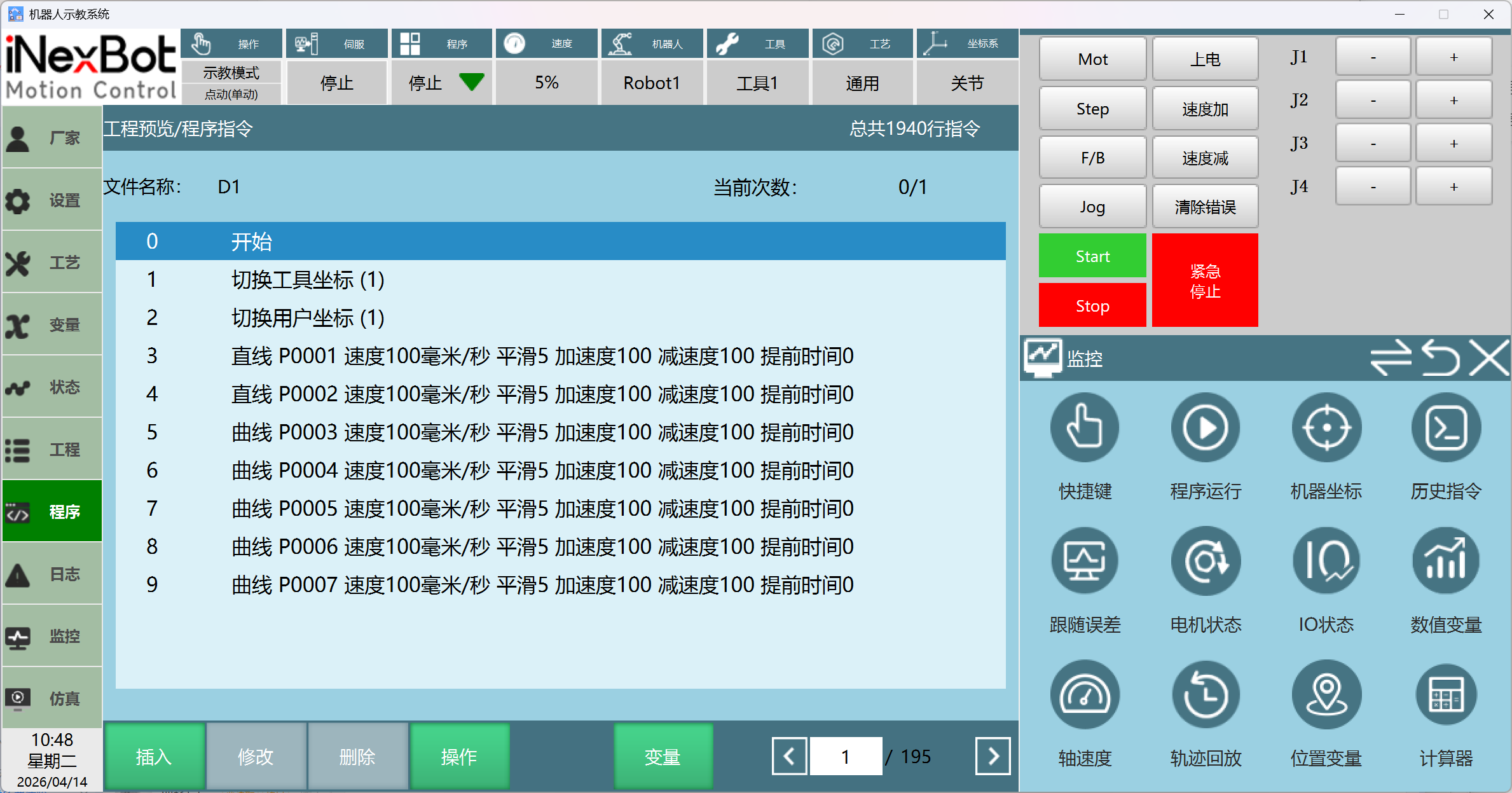
After the program is generated, it automatically jumps to the generated job file. You can also select the generated program in [Project] and open it; switch the teach pendant to run mode and press the [Start] button.
Note:
If you want to run this program in a loop, add a point-to-point instruction in joint coordinates at the first or last line of the program as a safety point. After setting the safety point, run the program to verify the trajectory is correct. An improperly set safety point may cause joint limits to be exceeded and result in abnormal trajectories.
Usage Examples
Example 1: Generating External TCP
Using a four-axis SCARA robot as an example:
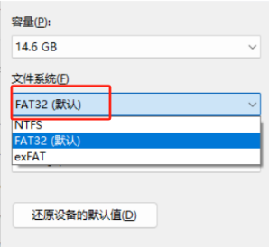
- First, place the DXF file on a USB drive and insert the USB drive into the teach pendant (FAT32 format USB drive is recommended).
- Click [Process] > [DXF] on the teach pendant.
- First enter the desired value in [Discrete Points] (only applies to splines; higher values generate more points in the job file; enter a reasonable value as excessive values may cause unsmooth trajectories).
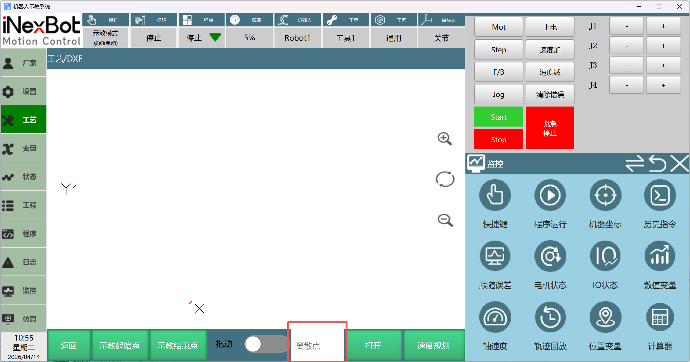
- ① Click the [Open] button. ② In the popup, select the mnt folder then enter the udisk folder. This folder contains the USB drive files. Find and open the DXF file as shown below.
- Calibrate the tool to determine the flange center.
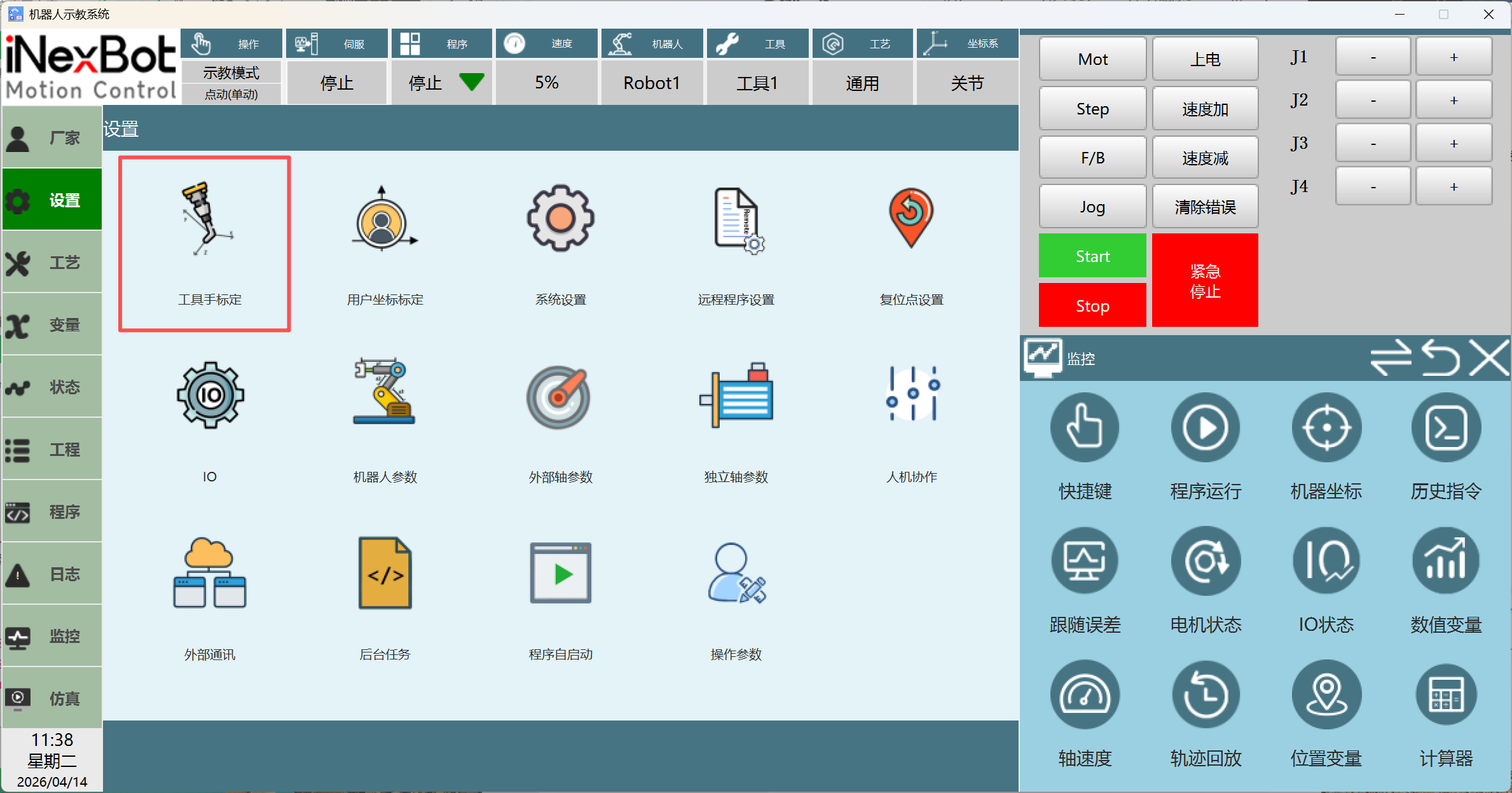
Step 1: Click [Settings] > [Tool Calibration]
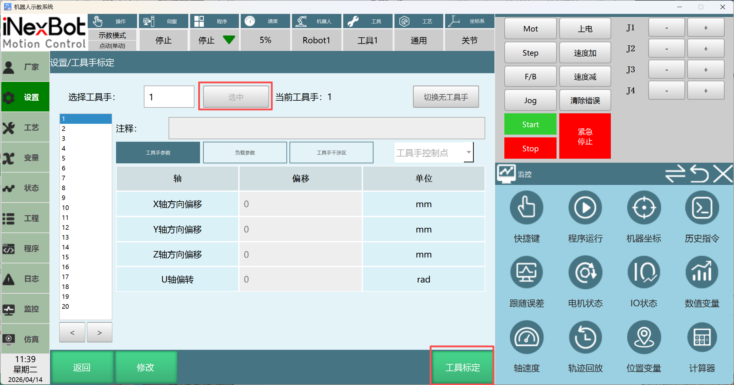
Step 2: In the No Tool state, click [Tool Calibration].
Step 3: For the four-axis SCARA robot, use the 2-point method for tool calibration.
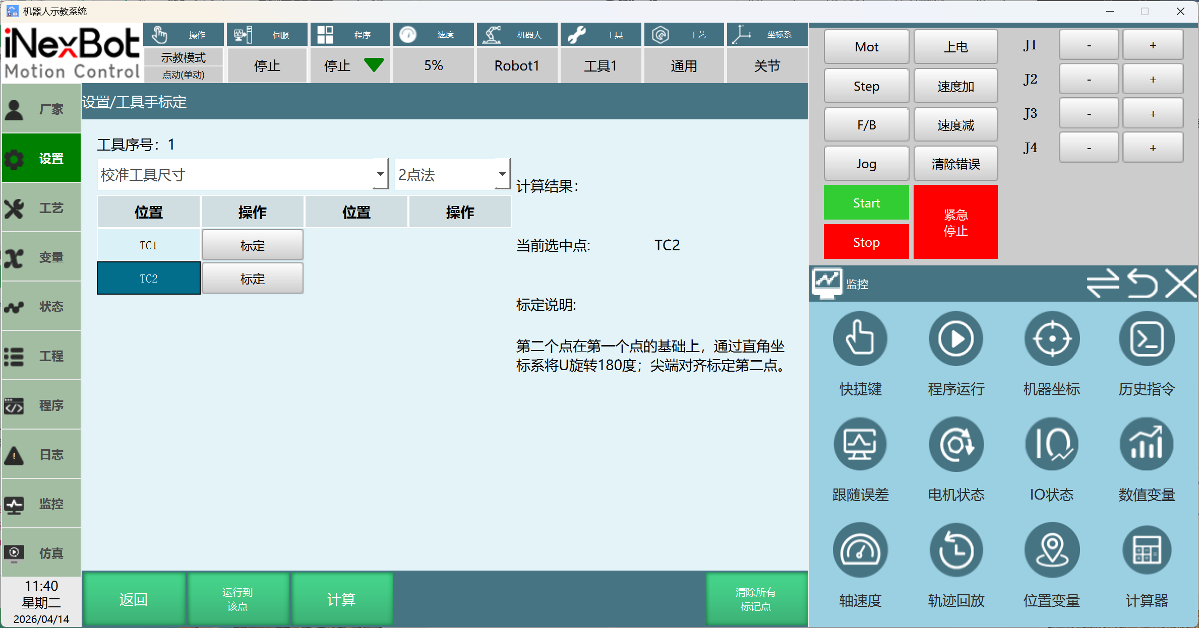
Step 4: TC1 is any point in space. Align the tool tip with the external tool tip and click Calibrate.
Step 5: TC2 is based on TC1 — jog the U-axis in Cartesian coordinates to 180° (you need to change the Configuration Value to degree values in [Operation Parameters] to see degrees), then move XYZ axes to align the tool tip with the external tool tip and click Calibrate.
Step 6: After two-point calibration, click Calculate.
Step 7: Select the calibrated tool.
- Calibrate the user coordinate system.
If using a tool, when calibrating the user coordinate, you must select the tool and calibrate the user coordinate with the tool attached (the calibrated user coordinates must be on the same horizontal plane, i.e., Z values must be consistent).
When calibrating the user coordinate system, pay attention to the calibration direction. After calibration, it is recommended to set the robot coordinate system to user coordinates and jog UZ to check the lift direction; sometimes the calibration direction is reversed, causing the lift direction to be negative.
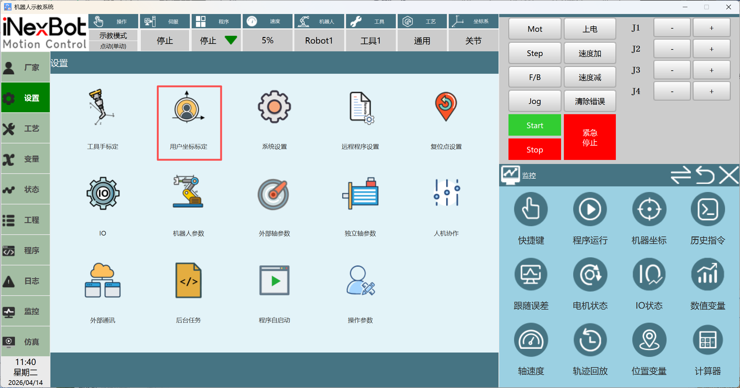
Step 1: Click [Settings] > [User Coordinate Calibration]
Step 2: Select the user coordinate number to calibrate.
Step 3: Click [User Calibration]
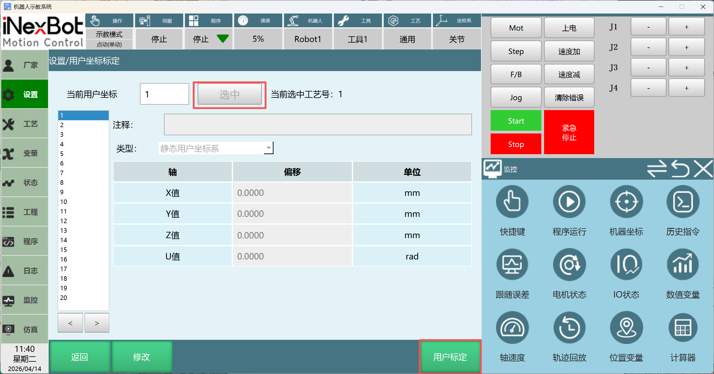
Step 4: Calibrate the user coordinate origin and XY axis directions (the calibrated user coordinates must be on the same horizontal plane, i.e., Z values must be consistent. If the Z values are inconsistent after marking, click Modify to manually enter the same Z value).
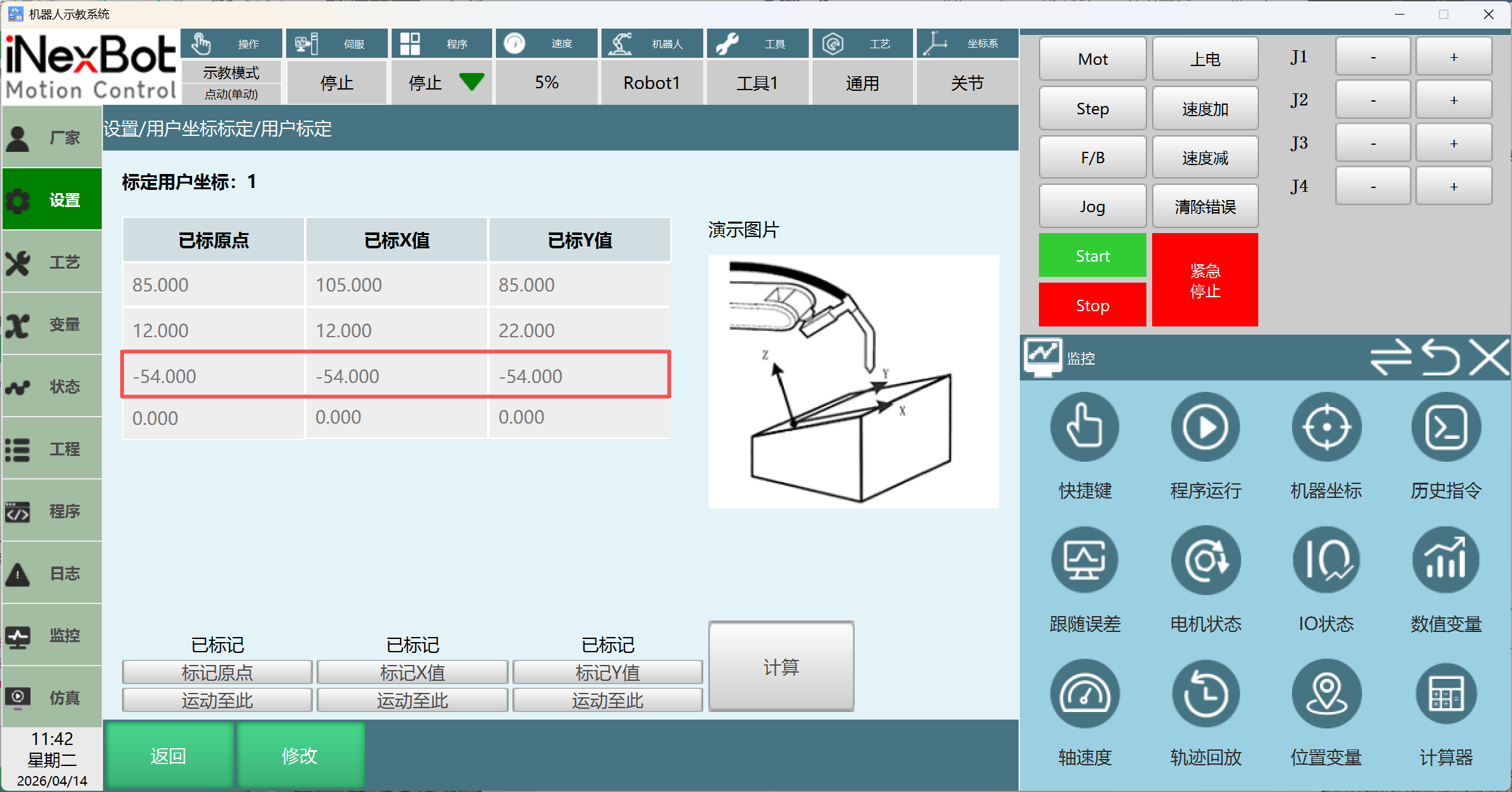
Step 5: Click Calculate.
- Place the workpiece; it can be placed in any position. After placement, before generating the job file, teach the start point and end point.
| Function | Description |
|---|---|
| Teach Start Point | The start point of the workpiece. Move the robot to align the trajectory start point with the external tool tip (if using a tool, select the tool number; if not using a tool, select "No Tool"). After alignment, click Teach Start Point. |
| Teach End Point | The end point of the workpiece. Move the robot to align the trajectory end point with the external tool tip (if using a tool, select the tool number; if not using a tool, select "No Tool"). After alignment, click Teach End Point. |
- Click Program Parameters, enter the program name, select the instruction type as External TCP, select the calibrated tool number, and select the calibrated user coordinate system. Fill in the correct speed, smoothing level, acceleration, deceleration, lift height, and lift speed values needed (if using lift height, toggle on "Insert Lift Points").
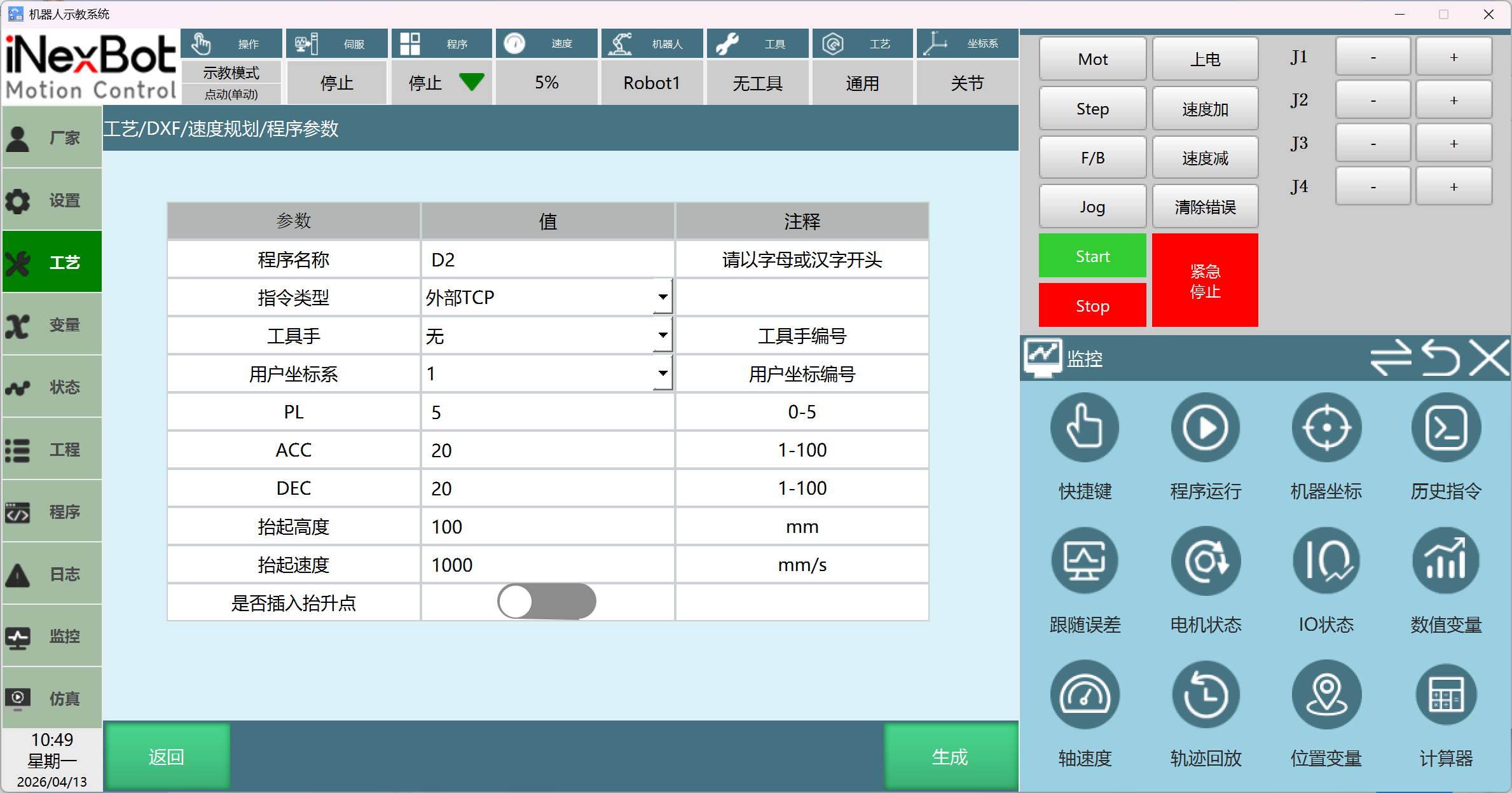
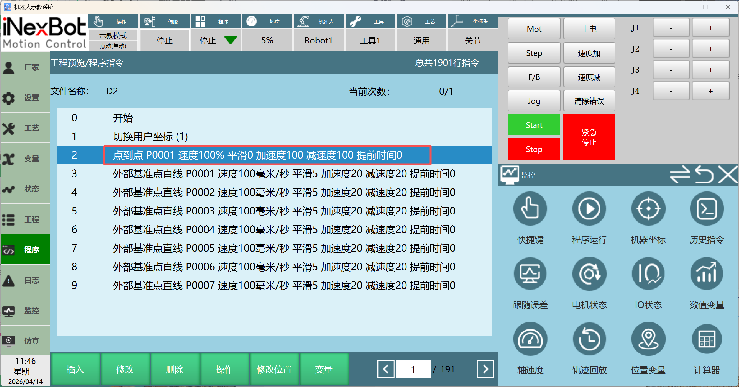
- Click Generate. The generated job file is stored in Project. Open the job file and run it.
The generated job file points are consistent with the hand system used during user coordinate calibration. That is, if left-hand calibration was used for user coordinates, the point hand system in the job file is left-hand; if right-hand calibration was used, the point hand system is right-hand.
For loop execution of the job file, manually insert a point-to-point instruction in joint coordinates at the first or last line of the program to return to a safe position (after setting the safety point, run the program to verify the trajectory is correct; an improperly set safety point may cause joint limits to be exceeded and result in abnormal trajectories).
Example 2: Generating TCP
Using a four-axis SCARA robot as an example:
- First, place the DXF file on a USB drive and insert the USB drive into the teach pendant (FAT32 format USB drive is recommended).
- Click [Process] > [DXF] on the teach pendant.
- First enter the desired value in [Discrete Points] (only applies to splines; higher values generate more points in the job file; enter a reasonable value as excessive values may cause unsmooth trajectories).
- ① Click the [Open] button. ② In the popup, select the mnt folder then enter the udisk folder. This folder contains the USB drive files. Find and open the DXF file as shown below.
- Calibrate the tool to determine the flange center.
Step 1: Click [Settings] > [Tool Calibration]
Step 2: In the No Tool state, click [Tool Calibration].
Step 3: For the four-axis SCARA robot, use the 2-point method for tool calibration.
Step 4: TC1 is any point in space. Align the tool tip with the external tool tip and click Calibrate.
Step 5: TC2 is based on TC1 — jog the U-axis in Cartesian coordinates to 180° (you need to change the Configuration Value to degree values in [Operation Parameters] to see degrees), then move XYZ axes to align the tool tip with the external tool tip and click Calibrate.
Step 6: After two-point calibration, click Calculate.
Step 7: Select the calibrated tool.
- Calibrate the user coordinate system.
If using a tool, when calibrating the user coordinate, you must select the tool and calibrate the user coordinate with the tool attached (the calibrated user coordinates must be on the same horizontal plane, i.e., Z values must be consistent).
When calibrating the user coordinate system, pay attention to the calibration direction. After calibration, it is recommended to set the robot coordinate system to user coordinates and jog UZ to check the lift direction; sometimes the calibration direction is reversed, causing the lift direction to be negative.
Step 1: Click [Settings] > [User Coordinate Calibration]
Step 2: Select the user coordinate number to calibrate.
Step 3: Click [User Calibration]
Step 4: Calibrate the user coordinate origin and XY axis directions (the calibrated user coordinates must be on the same horizontal plane, i.e., Z values must be consistent. If the Z values are inconsistent after marking, click Modify to manually enter the same Z value).
Step 5: Click Calculate.
- Click Program Parameters, enter the program name, select the instruction type as TCP, select the calibrated tool number, and select the calibrated user coordinate system. Fill in the correct speed, smoothing level, acceleration, deceleration, lift height, and lift speed values needed (if using lift height, toggle on "Insert Lift Points").
- Click Generate. The generated job file is stored in Project. Open the job file and run it.
The generated job file points are consistent with the hand system used during user coordinate calibration. That is, if left-hand calibration was used for user coordinates, the point hand system in the job file is left-hand; if right-hand calibration was used, the point hand system is right-hand.
For loop execution of the job file, manually insert a point-to-point instruction in joint coordinates at the first or last line of the program to return to a safe position (after setting the safety point, run the program to verify the trajectory is correct; an improperly set safety point may cause joint limits to be exceeded and result in abnormal trajectories).
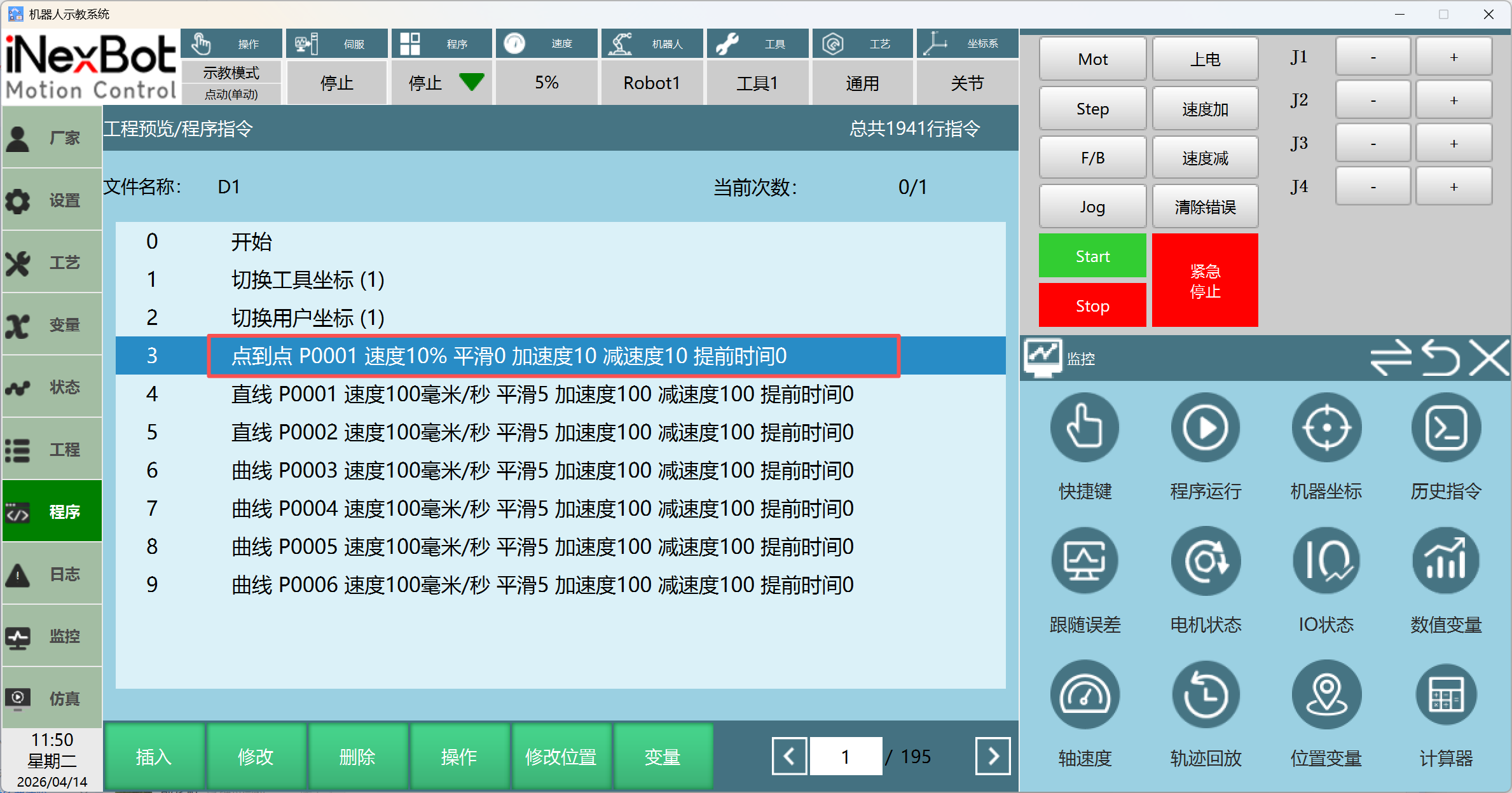
Note:
When generating a TCP job file, during execution the flange center (tool center) moves along the DXF trajectory. When generating an external TCP file, during execution every point of the workpiece (DXF trajectory) passes through the user coordinate origin.
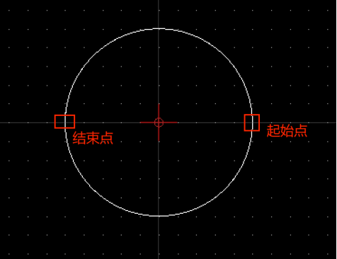
When using External TCP to generate a full circle trajectory, the trajectory end point is the position of the start point symmetrically reflected about the circle center, as shown below.
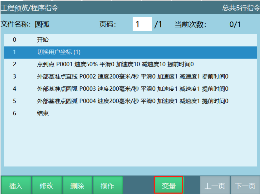
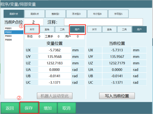
When using External TCP to generate a full circle or arc trajectory, due to small movement distances and large orientation changes, the execution speed may be too fast. Manually modify the instruction speed. When generating arc trajectories, if a dynamic limit exceeded error occurs, you can manually change the user coordinate to joint coordinate in [Variables], as shown below.
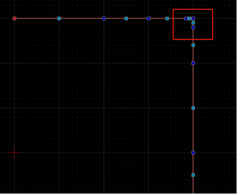
If the DXF graphics drawn in CAD contain right angles, it is recommended to insert closely spaced points on both sides of the right angle, as shown below.
CAD Usage Notes
After drawing with CAD, you must save the file in .dxf format.
When drawing with CAD, you can use entities such as lines, arcs, polylines, splines, and full circles, but try to use the same entity type to draw a single complete trajectory in one file.
Segmented drawing will affect the robot's motion trajectory (with segmented drawing, the robot runs each segment in the drawing order of the DXF file).
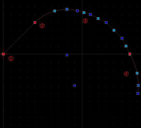
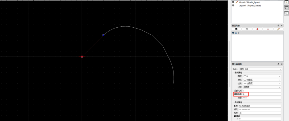
As shown above, if a lift height is filled in when generating the job file, the robot will: lift → run line ① → lift again → run arc ② → lift again → run polyline ③ → lift again → run arc ④.
If multiple entities are used, the robot's motion will be discontinuous at the junction of two entities. When generating the job file, if a lift height is filled in, each trajectory segment will have a lift; if no lift height is filled in, there may be stuttering at trajectory junctions. It is recommended to fill in a smoothing value for smooth operation.
If multiple entities are needed to draw a graphic, the start and end point directions of each trajectory segment must be consistent — the beginning of the next segment must connect to the end of the previous segment.
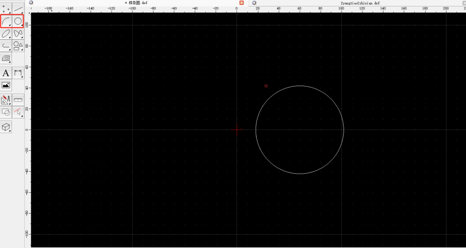
In QCAD, when using arc or circle entities, arc and circle trajectories run counterclockwise. If multiple entities are used, pay attention to the start point of each trajectory segment; the end point of the previous segment should be the same as the start point of the next segment. The arc start point is the counterclockwise starting point of that arc trajectory.
Q&A for Retrieval
Q: What entity types does the DXF function support?
A: The DXF function supports reading lines, arcs, polylines, splines, and full circle entities. Other entities are not currently supported.
Q: How to properly prepare a DXF file?
A:
- Draw using CAD software and export in .dxf format (QCAD drawing software is recommended)
- The workpiece and DXF file must be reproduced at a 1:1 scale; the workpiece origin must correspond to the graphics origin in the DXF file
- Delete unnecessary graphics; keep it as simple as possible, trying to make it a single complete continuous trajectory
- Try to use the same entity type to draw one complete trajectory per file
Q: What is the purpose of the discrete points parameter?
A: Discrete points only apply to splines. Higher discrete points values generate more points in the job file. Other supported entities do not require changing discrete points; use the default value. The maximum supported discrete points value is currently 5000.
Q: How to open a DXF file?
A:
- Insert a USB drive into the teach pendant (FAT32 format is recommended)
- Fill in the desired discrete points (only applies to splines)
- Click the [Open] button
- Select the corresponding DXF file in the popup
- Click [OK]
Q: What is the difference between TCP and External TCP?
A:
- TCP job file: During execution, the flange center (tool center) moves along the DXF trajectory
- External TCP file: During execution, every point of the workpiece (DXF trajectory) passes through the user coordinate origin
Q: What should I be aware of when using External TCP?
A:
- When using External TCP to generate a full circle trajectory, the end point is the start point symmetrically reflected about the circle center
- When using External TCP to generate full circle or arc trajectories, the execution speed may be too fast due to small movements and large orientation changes; manually modify the instruction speed
- When generating arc trajectories, if a dynamic limit exceeded error occurs, manually change the user coordinate to joint coordinate in [Variables]
Q: How to properly calibrate the tool and user coordinate system?
A:
- Tool calibration: In the No Tool state, click [Tool Calibration], use the 2-point method, then click [Calculate]
- User coordinate system calibration: If using a tool, select the tool and calibrate the user coordinate with the tool attached; the calibrated user coordinates must be on the same horizontal plane (Z values must be consistent)
Q: How to run the generated program in a loop?
A: Add a point-to-point instruction in joint coordinates at the first or last line of the program as a safety point. After setting the safety point, run the program to verify the trajectory is correct. An improperly set safety point may cause joint limits to be exceeded and result in abnormal trajectories.
Q: Why does the generated job file trajectory not match expectations?
A: Possible causes include:
- Tool not properly calibrated
- User coordinate system not properly calibrated
- Cluttered graphics or segmented drawing in the DXF file
- Improper discrete points setting
- Improper lift height setting
Q: What should I be aware of when using multiple entities?
A:
- The start and end point directions of each trajectory segment must be consistent; the beginning of the next segment must connect to the end of the previous segment
- In QCAD, when using arc or circle entities, trajectories run counterclockwise
- If using multiple entities, the end point of the previous segment should be the same as the start point of the next segment
- If a lift height is filled in when generating the job file, the robot will lift before and after each trajectory segment
- If no lift height is filled in, there may be stuttering at trajectory junctions; it is recommended to fill in a smoothing value for smooth operation
Version History
| Version | Date | Changes | Author |
|---|---|---|---|
| 1.0.0 | 2026-06-30 | Initial version | MUZI165 |