Vision Process
| Instruction Type | Foreground | Global Background | Local Background |
|---|---|---|---|
| Start Vision | Supported | Supported | Supported |
| Trigger Vision | Supported | Supported | Supported |
| Get Vision Position Count | Supported | Supported | Supported |
| Get Vision Position | Supported | Supported | Supported |
| Clear Vision Position Info | Supported | Supported | Supported |
| End Vision | Supported | Supported | Supported |
| Instruction Type | Single-Step | Reverse | Pre-Execute | Test Run | Pre-Executed |
|---|---|---|---|---|---|
| Start Vision | Supported | Supported | |||
| Trigger Vision | Supported | Supported | |||
| Get Vision Position Count | Supported | Supported | |||
| Get Vision Position | Supported | Supported | |||
| Clear Vision Position Info | Supported | Supported | |||
| End Vision | Supported | Supported |
Process Introduction
Identify and locate workpieces so that the robot can perform more precise grasping operations. It has advantages such as precise positioning, easy deployment, simple to use, flexible parameter configuration methods, and rich instructions. We often combine it with conveyor belt process, which can effectively track and grasp workpieces using simple programming.
Parameter Settings
Click Process - Vision Process to enter the vision process parameter settings interface, as shown:
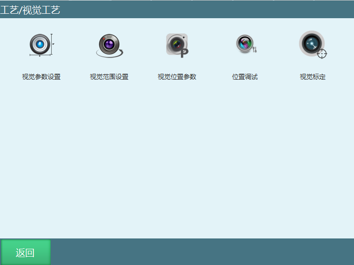
Vision Parameter Settings
The vision parameter settings interface is shown:
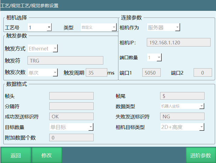
- Camera Selection:
| Parameter | Description |
|---|---|
| Process Number | Provides 1-99 process numbers, each process number saves all vision parameters and vision position parameters under that process number |
| Type | Currently supports custom type and delta; Custom: users can set parameters according to their needs; Delta: custom protocol for custom customers, after selecting this option, custom set parameters are invalid |
- Trigger Method
| Parameter | Description |
|---|---|
| IO | Give the camera a trigger signal, here you need to set the IO signal port and the camera hardwired to the corresponding IO |
| Ethernet | Generally defaults to Ethernet sending. When the camera receives "TRG" (or user-defined string), it should reply with coordinate values to the controller |
| Trigger Condition - Single Trigger | When the condition is single trigger, only triggers once when running the vision trigger instruction |
| Trigger Condition - Continuous Trigger | When the condition is continuous trigger, continuously triggers when running the vision trigger instruction |
| Trigger Cycle | Time interval during continuous trigger |
- Connection Parameters
| Parameter | Description |
|---|---|
| Camera IP | When the camera is a server, fill in the camera IP here. The camera's IP address and controller's IP address must be in the same network segment. When the camera is a client, the IP address here is the current connected controller's IP address. When the camera is a client, the controller is the server, requiring the camera to actively connect |
| Camera | Client, Server |
| Port Count | If the vision server uses the same port for data send/receive, the port count is 1; if data send/receive uses different ports, the port count is 2. Port 1 is for receiving data, Port 2 is for sending data (port numbers cannot be set the same) |
- Data Format
| Parameter | Description |
|---|---|
| Frame Header | Frame header before sending position data, must be the same as the camera configured parameters |
| Separator | Separator between each data when sending position data, must be the same as the camera configured parameters (separator cannot be set to empty) |
| Frame Trailer | End character after sending position data. Must be the same as the camera configured parameters |
| Data Type | Robot coordinates, pixel coordinates, conveyor pixel coordinates, conveyor robot coordinates. 1. Robot coordinates: data sent by the camera is the robot's coordinates 2. Pixel coordinates: data sent by the camera is pixel coordinates under the camera coordinate system 3. Conveyor pixel coordinates: this function is used for the controller to do hand-eye calibration, the camera captures conveyor pixel coordinates, see "Conveyor Process Manual" 4. Conveyor robot coordinates: after the camera completes hand-eye calibration, the controller performs secondary calibration to increase data accuracy |
| Success Send Marker | After the camera takes a photo and successfully identifies the workpiece, it sends a success marker |
| Failure Send Marker | After the camera takes a photo and identification fails, it sends a failure marker |
| Target Count | Single target: can only identify one target point Multi-target: can identify multiple target points Single target data example format: @,x,y,Rz,$ ("@" represents frame header; "," represents separator; "$" represents end character; "x,y,Rz" represents specific sent point coordinate values) Multi-target data example format: @,N,x,y,Rz,x,y,Rz,$ ("@" represents frame header; "N" represents number of sent point data; "," represents separator; "$" represents end character; "x,y,Rz" represents specific sent point coordinate values) |
| Camera Target Type | 2D, 2D+Height, 3D Example: (frame header "!" separator "," frame trailer "$") 2D: sent data format: !,X,Y,Rz,$ 2D+Height: sent data format: !,X,Y,Rz,h,$ 3D: sent data format: !,X,Y,Z,A,B,C,$ |
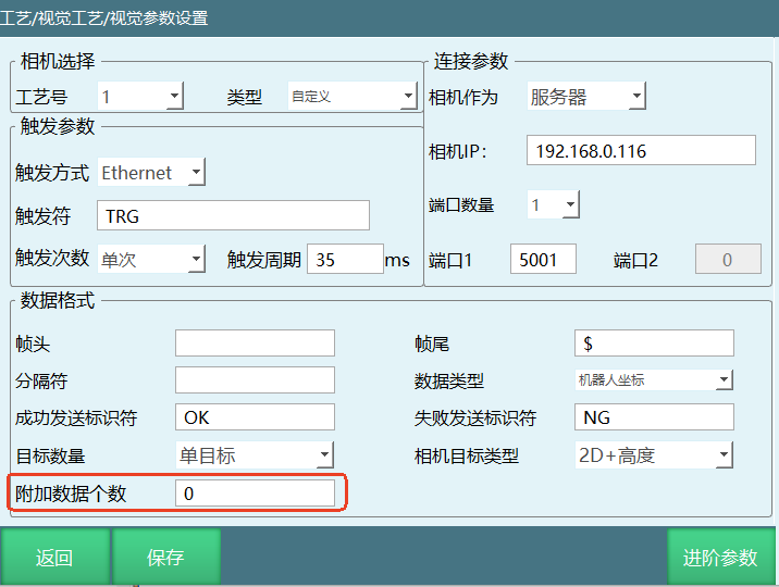
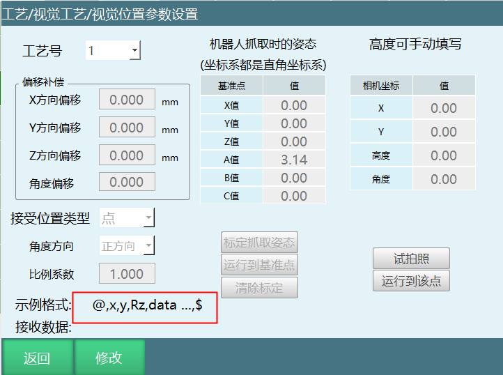
| Additional Data Count | Stores data sent by the camera besides position (tool hand number, color, whether position is valid, etc.). User-defined additional data values will default to the first variable GS001, stored sequentially according to additional data count Example: custom 1 represents black, camera sends additional data 1, after parsing to variable, the camera captures black workpiece, then we can define variable value as 1 through conditional judgment, robot grasps black workpiece Single target format: !,X,Y,Rz,data ...,$ Multi-target format: !,N,X,Y,Rz,data ...,X,Y,Rz,data ...,$ |
- Advanced Parameters
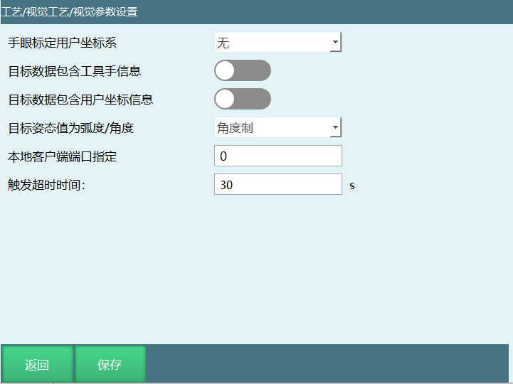
| Parameter | Description |
|---|---|
| Hand-Eye Calibration User Coordinate System | This system supports vision positions corresponding to user coordinate system, i.e., positions sent by the camera are positions in the vision coordinate system. Here you need to select a user coordinate system that has been matched with the camera. Note: As shown above, if you select None, it defaults to the camera sending positions under Cartesian coordinate system |
| Target Data Contains Tool Hand Info | Open this enable, positions sent by the camera contain the tool hand used (for multiple tool hand operations) |
| Target Data Contains User Coordinate Info | Open this enable, positions sent by the camera contain the user coordinate system used (for multiple worktables). Note: Before opening user enable, hand-eye calibration user coordinate system cannot be None (when closed, needs to be set to None). User and tool enables can be opened/closed simultaneously |
| Target Attitude Value is Radians/Degrees | Select unit type for A/B/C axis or U axis in vision position parameters. Radian unit is rad, degree unit is ° (degree). Note: Angle/radian setting only affects the system's display of received data angle/radian content |
| Local Client Port Specification | The system specifies a fixed port to connect to the camera server, can quickly identify a device IP for connection. Range [0-65535] |
| Trigger Timeout | After triggering the camera, if the camera does not return data within the set time, it will timeout and report error. Range [0-5000] |
Vision Range Setting
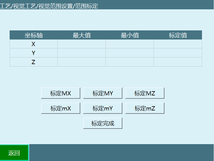
To avoid the position parameters returned by the camera exceeding the robot's reachable range, the maximum range the robot can reach is specified. If the camera returns parameters exceeding the range, a warning will be given and the data will be automatically filtered and not take effect. Calibration can be done by manual teaching method or by directly filling in parameters.
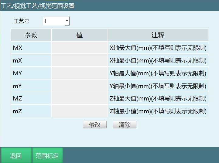
Process Number: Provides 1-99 process numbers, each process number saves the vision range parameters under that process number.
Range Calibration: Calibrate the maximum and minimum values of XYZ three axes under Cartesian coordinate system.
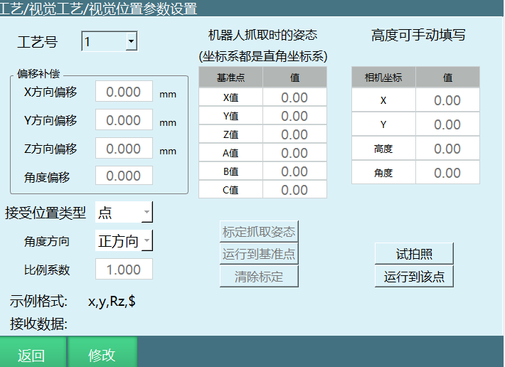
Process Number: Provides 1-99 process numbers, each process number saves the vision position parameter settings under that process number.
Offset Compensation: If each robot grasp position has a fixed direction offset from its actual position, fill in the compensation amount here, and it will automatically compensate to the correct position.
Scale Factor: If the position value sent by the camera is sent after being scaled by a specific ratio, you need to fill in the scale factor here. For example, if the camera sends values (300,200,100) and the actual position is (3,2,1), then fill in 0.01 here.
Compensation Amount: The Cartesian coordinate value deviation between the workpiece grasp position and the actual position.
Calculation Formula: Scale Factor = Actual Position Value / Camera Sent Position Value.
Angle Direction: Camera sent point position same or opposite to robot rotation angle.
Receive Position Type: Point/Trajectory.
Point: Camera takes photo and sends point position to controller.
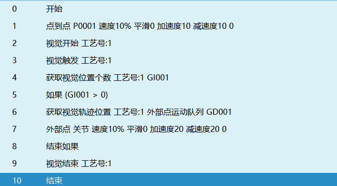
Trajectory: After the camera identifies the trajectory, it sends a series of point positions, run the trajectory through external point instruction.
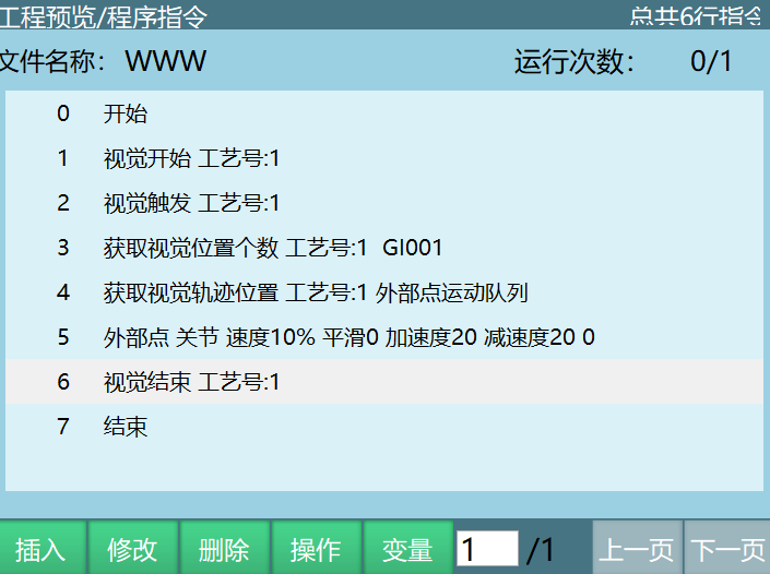
When receive position type is selected as trajectory, the program job file is as follows:
- Robot Grasp Attitude
Calibrate Grasp Attitude: Here you need to mark the robot's end attitude when grasping the object. After calibration, each grasp will use this attitude for grasping (the XYZ values here do not affect the grasp position). If the shooting target has angle changes, the final angle = calibrated C value + camera sent C value.
Run to Reference Point: Run to the point position calibrated when calibrating grasp attitude.
Clear Calibration: Clear the point position data of calibrated grasp attitude.
- Camera Coordinates
Camera Coordinates: If the camera cannot send grasp height, you need to fill in the grasp height Z in the right table. If the camera can send grasp height, this setting is invalid. After setting, hold the DEADMAN button to power on, click [Test Photo] button to take a photo test. Data sent by the camera will be displayed in camera coordinates and received data.
Run to This Point: After taking a photo, hold the DEADMAN button to power on, click [Run to This Point] button to move the robot to the photo position to verify accuracy.
Test Photo: Servo powered on, click test photo, open network connection, receive data sent by communication device. If it doesn't match the example format, trigger a warning reminder.
Example Format: Verify and arrange according to the connection parameters set in the vision parameter settings interface.
For example 2D+Height: In connection parameters, frame header is @, separator is ,, end character is $, then format is @,x,y,Rz,h,$.
Received Data: Position sent by camera.
For example: Camera sends position x=100, y=-50, Rz=1, h=1000, here received data displays as @,100,-50,1,1000,$.
Position Debugging
Used in combination with conveyor belt, used for conveyor belt debugging. After the camera takes a photo, it will send a point position data that exists in both [Original Point Position] and [Offset Point Position]. But the workpiece will be transported a distance by the conveyor belt. Click Calculate Offset, the calculated offset position will overwrite [Offset Point Position]. Click Run to This, the robot will directly go to the calculated offset position.
Enter from "Process" - "Vision Process" - "Position Debugging", used for debugging conveyor belt when using vision plus conveyor belt tracking process.
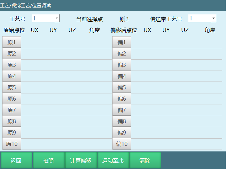
Process Number: Vision process number.
Current Selected Point: Select the point position that needs to move to.
Conveyor Belt Process Number: The conveyor belt process number that needs debugging.
Photo: Hold the DEADMAN button to power on, click [Photo] button to take a photo test. Position data sent by the camera will be displayed in [Original Point Position] and [Offset Point Position].
Run to This: After taking a photo, hold the DEADMAN button to power on, select the point position and click [Run to This] button, the robot will move to the position sent by the camera.
Calculate Offset: After taking a photo, open the conveyor belt to transport the workpiece a distance, click Calculate Offset will display the offset workpiece point position in [Offset Point Position] on the right.
Clear: Clear all point positions.
Vision Calibration
The purpose of vision calibration is to calibrate the transformation relationship from the camera coordinate system to the robot coordinate system, thereby determining the position coordinates of the target identified by the camera in the robot coordinate system, and finally achieving robot movement to the target position.
According to whether the camera is installed on the robotic arm, the calibration methods are mainly divided into Eye-in-Hand and Eye-to-Hand. Detailed operation instructions are provided below.
- Eye-in-Hand
Used when the camera is on the tool hand. The camera lens plane should be roughly parallel to the calibration template plane, and the relative height between the camera and the calibration template should remain unchanged throughout the calibration process. By marking the robot's current point position information, these positions must satisfy at least 3 unchanged attitude positions and 3 changed attitude positions. Run calculation, the robotic arm with the camera goes to the current robot's positions, obtains corresponding pixel data. After all pixel data is obtained, calculate the transformation relationship between camera data and robot positions. Subsequently sent camera positions can be transformed into actual robot motion positions through this transformation relationship.
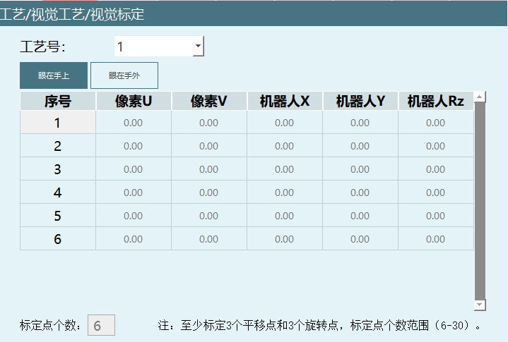
Process Number: Vision process number.
Calibration Point Count: Number of points that need to be taught, calibration point count range (6-30).
Points: At least 6 points need to be calibrated, maximum 30 points. The calibrated points require at least three different positions and three different attitudes. For example (move X axis, Y axis to mark three points, then move C axis to calibrate three points).
Mark This Point: Record current robot point position data.
Move to This Point: Hold the DEADMAN button to power on, select the serial number and click [Run to This] button, the robot will move to the point position marked by that serial number.
Clear This Point: Clear the point position data of the selected serial number, do not clear pixel data. Pixel data will be re-photographed after running calculation.
Run Calculation: Click Run Calculation, the robot will automatically move to each point according to the previously taught point position data. Each time it moves to a point, it will trigger a photo, record the current pixel data. After motion data collection is complete, automatically perform calibration calculation and pop up the calculation result.
- Eye-to-Hand
The camera is fixedly installed on a fixed bracket (photographing from top to bottom), or installed below the target (photographing from bottom to top). The camera lens plane should be roughly parallel to the calibration template, and the relative height between the camera and the calibration template should remain unchanged throughout the calibration process.
Note: The calibration template is fixed at the end of the robotic arm tool hand.
Method Introduction: This calibration method is divided into 3 steps: hand-eye calibration, robotic arm tool hand calibration, and high-precision tool hand calibration.
Note: This method can only calibrate the tool hand offset on the field of view plane, so it is suitable for SCARA robots.
Steps:
①9-point (16-point) hand-eye calibration: Move the robotic arm so that the tool hand end template is placed in the center area of the field of view. After clicking "Run Calculation", the system will automatically calculate 9 (16) positions and move to each position in sequence, collecting 9 groups (16 groups) of position coordinates (pixel coordinates and robot without tool hand coordinates). After completion, the system automatically calculates the transformation relationship from camera pixel coordinates to robot coordinates.
②Tool hand calibration: Move the robotic arm to the first marked point in step 1, then use the end flange center as the calibration plane center, rotate the tool hand in both positive and negative directions by a certain angle, and collect 2 groups of position coordinates (pixel coordinates and robot without tool hand coordinates) in sequence. After completion, the system will automatically calculate the tool hand.
③High-precision tool hand calibration: Move the robotic arm to the first marked point in step 1, then use the tool hand end calculated in step 2 as the center, rotate around the center on the calibration plane by step angle (i.e., tool hand position unchanged, attitude changed) 6 times, recording 6 groups of position coordinates (pixel coordinates and robot without tool hand coordinates) in sequence. After completion, move to the first point again, rotate 6 times in the opposite direction by step angle. After completion, return to the first point again, rotate 6 times in the first rotation direction and record coordinates. Finally, the system will calculate a high-precision tool hand.
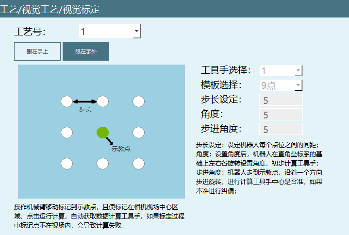
Tool Hand Selection: Select the tool hand to be calibrated.
Template Selection: Divided into 9-point and 16-point.
Note: The 9-point calibration range is a nine-grid. You need to test whether the robot coordinates at the four corners can be captured. If not, adjust the camera shooting range or reduce the step distance between each point. Same for 16-point calibration.
Step Length Setting: Based on the current robot position, automatically calculate the distance between 9 points (16 points).
Angle: After setting the angle, the robot rotates left and right by the set angle based on the Cartesian coordinate system to initially calculate the tool hand.
Step Angle: In step 3 high-precision tool hand calibration, the angle the robot steps and rotates around the tool hand end in one direction.
Vision Instructions
VISION_RUN - Start Vision
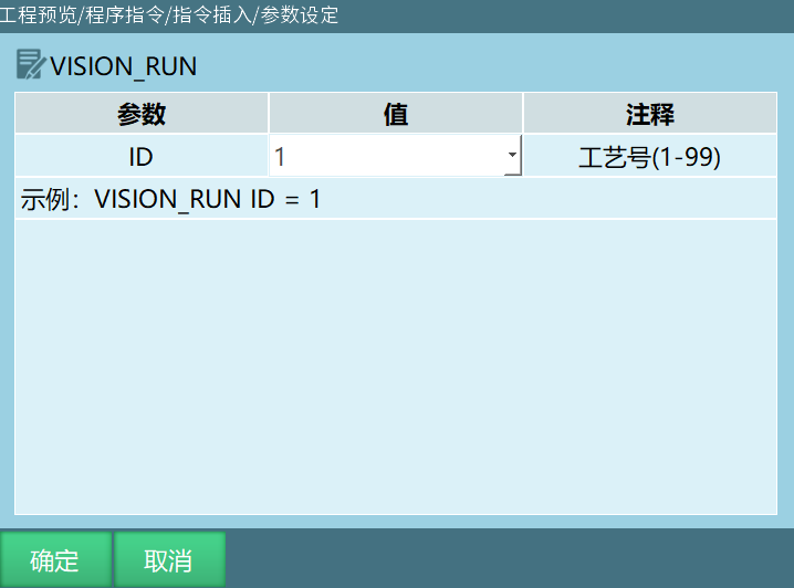
Format: VISION_RUN [Instruction Name] ID=1 [Process Number].
Function: After executing the start vision instruction, the controller connects to the camera.
Parameters:
| Parameter | Description |
|---|---|
| ID | Range [1,99], the process number selected in the instruction must match the process number selected in the vision process interface |
VISION_TRG - Trigger Vision
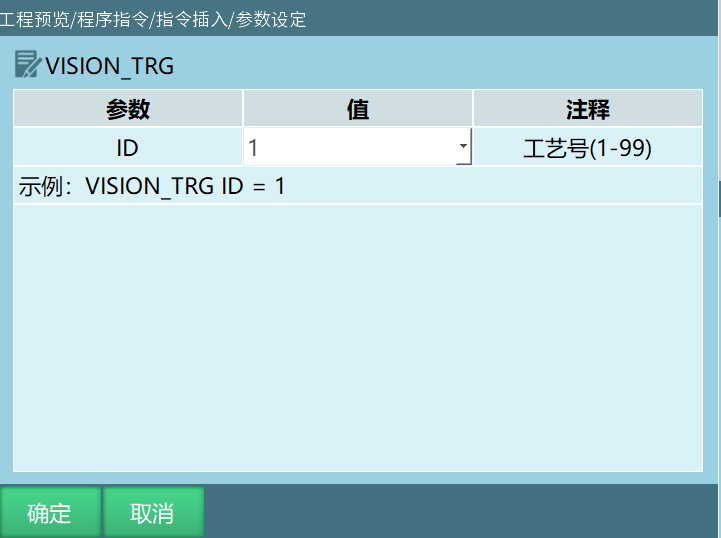
Format: VISION_TRG [Instruction Name] ID=1 [Process Number].
Function: After executing the trigger vision instruction, wait for the vision server's return value (sent position data). After obtaining the position data, continue running the next instruction.
Parameters:
| Parameter | Description |
|---|---|
| ID | Range [1,99], the process number selected in the instruction must match the process number selected in the vision process interface |
Description: Specific trigger method is set in the vision process - vision parameter settings interface:
Select IO trigger, running this instruction will send the corresponding IO signal
Select Ethernet method, running this instruction will send a custom string to the camera.
VISION_POSNUM - Get Vision Position Count
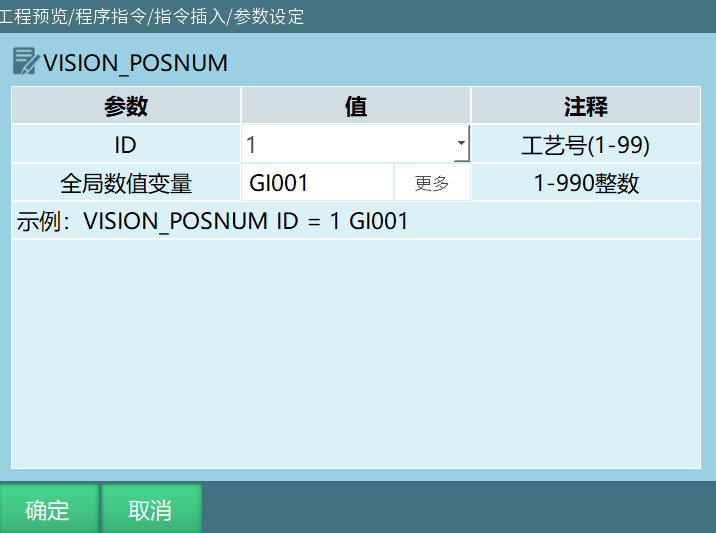
Format: VISION_POSNUM [Instruction Name] ID=1 [Process Number] GI001 [Global Numeric Variable].
Function: Record the number of positions sent by the camera, store the position count into the selected variable.
Parameters:
| Parameter | Description |
|---|---|
| ID | Range [1,99], the process number selected in the instruction must match the process number selected in the vision process interface |
| Global Numeric Variable | Store the number of positions sent by the camera into the selected variable. For example: camera sent three position data, selected variable is GI001. After executing this instruction GI001=3. Note: Each time the get position instruction is executed, the position count decreases by one |
Example:
NOP
VISION_RUN ID = 1 Start Vision
VISION_TRG ID = 1 Trigger Vision
VISION_POSNUM ID = 1 GI001 Get Vision Position Count
VISION_END ID = 1 End Vision
END
Example Description: Execute line 2 instruction to successfully communicate with camera. Execute line 3 instruction to trigger vision camera to send position information. Execute line 4 instruction to store the number of positions sent by vision into variable GI001. If vision sent 3 positions, after executing this instruction GI001=3.
VISION_POS - Get Vision Position
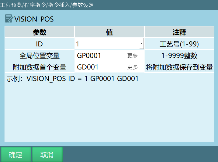
Format: VISION_POS [Instruction Name] ID=1 [Process Number] GP001 [Global Numeric Variable] I/GI/D/GD/S/GS [Additional Data Variable].
Function: Execute this instruction to store the position information sent by the camera into variables.
Parameters:
| Parameter | Description |
|---|---|
| ID | Range [1,99], the process number selected in the instruction must match the process number selected in the vision process interface |
| Global Position Variable | Position information sent by the camera is sequentially cached in the selected global position variable. For example: global position variable is GP0001, camera sends two positions. Execute get vision position instruction will store position information into variable GP0001. First time running this instruction GP0001 stores the first position info, second time running this instruction GP0001 stores the second position info |
| Additional Data First Variable | Variable type: integer, floating-point, string. Execute this instruction will store the defined additional data sequentially into variables. The additional data count needs to be set in vision process - vision parameter settings interface. For example: set additional data count to 2, additional data first variable is GD001. Execute this instruction will store the defined additional data into GD001, GD002. The use of additional data will be explained as examples later in this chapter manual (writing multiple different additional data and single data) |
Example:
NOP
VISION_RUN ID = 1 Start Vision
VISION_TRG ID = 1 Trigger Vision
VISION_POS ID = 1 GP0001 Get Vision Position
VISION_END ID = 1 End Vision
END
Example Description: Execute line 2 instruction to successfully communicate with camera. Execute line 3 instruction to trigger vision camera to send position information. Execute line 4 instruction to store the position information sent by vision into variable GP0001. If vision sent 3 positions, first time running get position instruction GP0001 stores the first position info, second time running get position instruction GP0001 stores the second position info, third time running get position instruction GP0001 stores the third position info.
VISION_CLEAR - Clear Vision Position Info
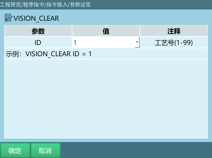
Format: VISION_CLEAR [Instruction Name] ID=1 [Process Number].
Function: Clear the position information sent by the camera in the current process number.
Parameters:
| Parameter | Description |
|---|---|
| ID | Range [1,99], the process number selected in the instruction must match the process number selected in the vision process interface |
Example:
NOP
VISION_RUN ID = 1 Start Vision
VISION_TRG ID = 1 Trigger Vision
VISION_POSNUM ID = 1 GI001 Get Vision Position Count
VISION_POS ID = 1 GP0001 Get Vision Position
VISION_CLEAR ID = 1 Clear Vision Position Info
VISION_END ID = 1 End Vision
END
Example Description: Execute line 2 instruction to successfully communicate with camera. Execute line 3 instruction to trigger vision camera to send position information. Execute line 4 instruction to store the number of positions sent by vision into variable GI001 (assume vision sent 3 positions, variable GI001=3, each time the get vision position instruction is executed, GI001 variable's stored position count decreases by 1). Execute line 5 instruction to store the position data sent by vision into variable GP0001 (assume vision sent 3 positions, first time running get position instruction GP0001 stores the first position info, second time running get position instruction GP0001 stores the second position info, third time running get position instruction GP0001 stores the third position info). Execute line 6 instruction will clear all position information sent by vision for the current process number.
VISION_END - End Vision
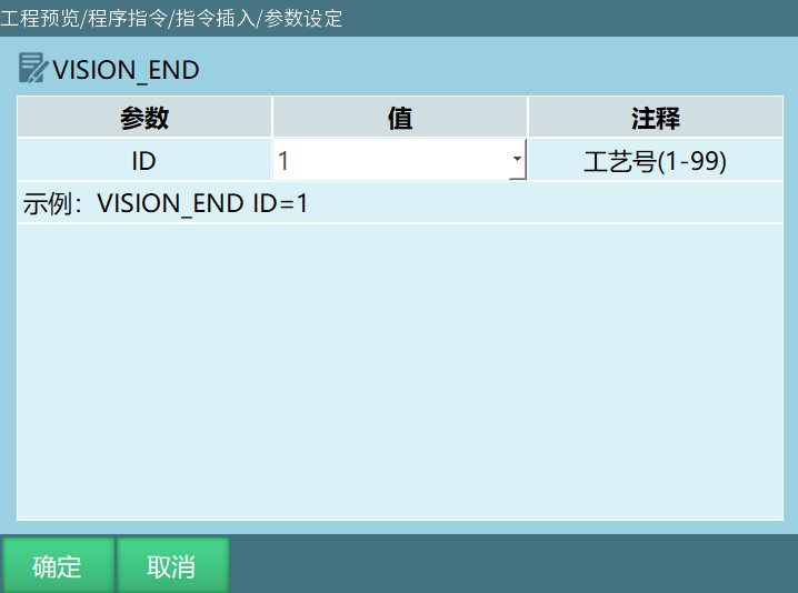
Format: VISION_END [Instruction Name] ID = 1 [Process Number].
Function: End the vision process, controller disconnects from camera.
Parameters:
| Parameter | Description |
|---|---|
| ID | Range [1,99], the process number selected in the instruction must match the process number selected in the vision process interface |
VISION_TRACE - Get Vision Trajectory Position
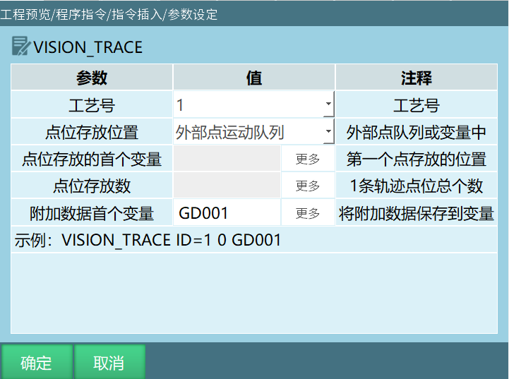
Format: VISION_TRACE [Instruction Name] ID = 1 [Process Number]; 0/1 ["0" means position storage is external axis motion queue, "1" means position storage is variable] P/GP [First variable for position storage] I/GI [Position storage count]; I/GI/D/GD/S/GS [Additional data first variable].
Function: When the camera sends multiple positions, you can choose different position storage methods to run trajectories.
Parameters:
| Parameter | Description |
|---|---|
| Process Number | Range [1,99], the process number selected in the instruction must match the process number selected in the vision process interface |
| Position Storage Location | Variable, external point motion queue. Variable (sent positions stored in variables). External point queue (after camera sends positions, insert external point instruction below the get trajectory position instruction, so the program can run external point trajectories) |
| First Variable for Position Storage (default GP0001) | When position storage location selects external point motion queue, this parameter cannot be modified. When position storage location selects variable, variable types P,GP,P[],GP[]. After camera sends positions, they will be stored in the selected first variable. The stored position variables will be stored sequentially according to position count and selected first variable. For example: camera sends 3 positions, selected first variable is GP0005, position data stored in variables GP0005,GP0006,GP0007 |
| Position Storage Count (default I001) | When position storage location selects external point motion queue, this parameter cannot be modified. Position storage count type can choose I,GI,I[],GI[] four types. The number of positions sent by camera is stored in the selected variable. For example: camera sends 4 positions, selected position storage count variable is I005. When running get trajectory run instruction, variable I005=4 |
| Additional Data First Variable (default GD001) | Variable type: integer, floating-point, string. Execute this instruction will store the defined additional data sequentially into variables. The additional data count needs to be set in vision process - vision parameter settings interface. For example: set additional data count to 2, additional data first variable is GI001. Execute this instruction will store the defined additional data into GI001,GI002 |
ONFLY_INIT - Start Flying Shot
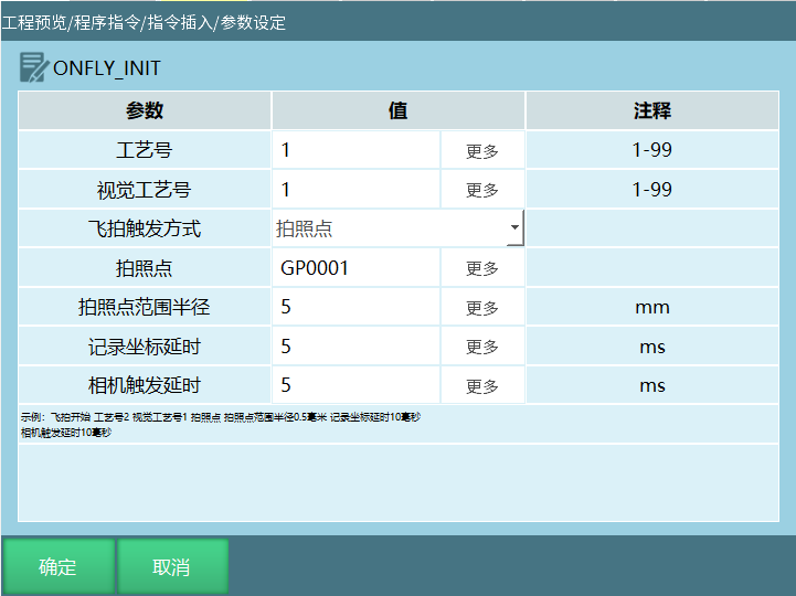
Flying Shot Function: When the robot tool hand moves past the photo point, quickly trigger the camera to take a photo. During the photo process, the object or camera is in motion.
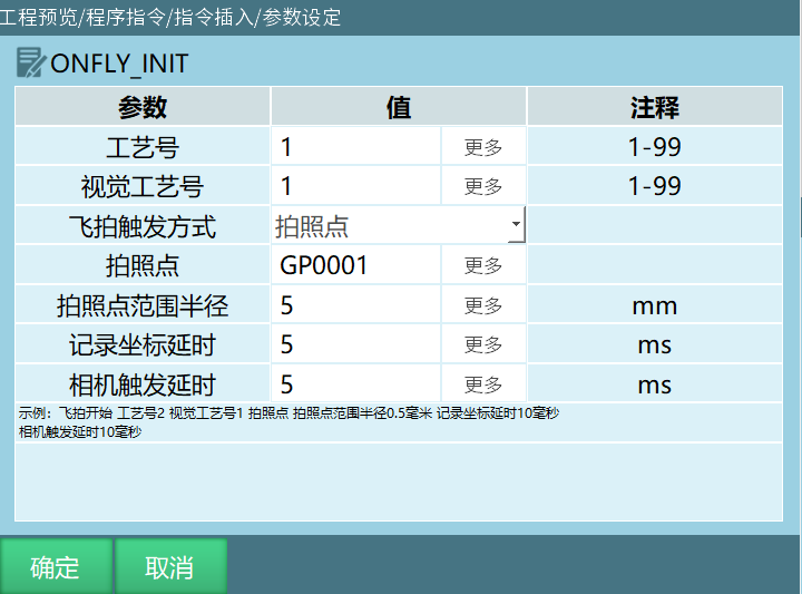
- Flying Shot Trigger Method: Photo Point
Format: ONFLY_INIT [Instruction Name]; ID [Vision Flying Shot Process Number]; VISIONID [Vision Process Number Bound to Flying Shot]; TYPE [Photo Point]; RADIUS [Photo Point Range Radius]; DELAY [Record Coordinate Delay]; CAMERA_TRIGGER_DELAY [Camera Trigger Delay].
- Flying Shot Trigger Method: IO Signal
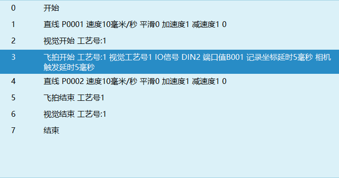
Format: ONFLY_INIT [Instruction Name]; ID [Vision Flying Shot Process Number]; VISIONID [Vision Process Number Bound to Flying Shot]; TYPE [IO]; VALUE [Port Value]; DELAY [Record Coordinate Delay]; CAMERA_TRIGGER_DELAY [Camera Trigger Delay].
Function: Start the flying shot task.
- Flying Shot Trigger Method: Single Axis
Format: ONFLY_INIT [Instruction Name]; ID [Vision Flying Shot Process Number]; VISIONID [Vision Process Number Bound to Flying Shot]; TYPE [Single Axis]; TRIGGER_START_POS [Trigger Start Position]; TRIGGER_COUNT [Trigger Count]; ANGLE_SPACING [Trigger Angle Spacing]; DELAY [Record Coordinate Delay]; CAMERA_TRIGGER_DELAY [Camera Trigger Delay].
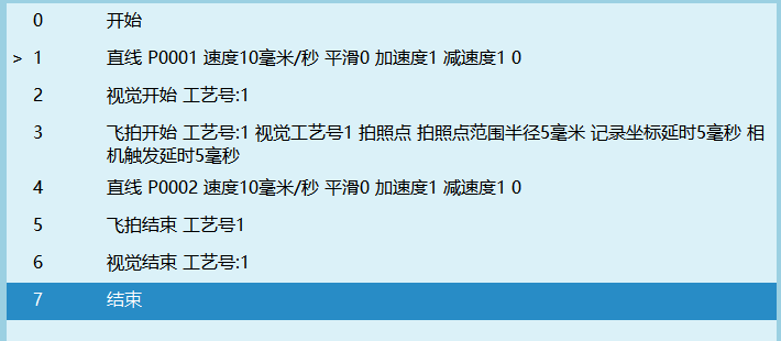
Note: Photo point method only supports linear instructions, and does not support smoothing.
Single axis method does not support linear instructions.
Parameters:
| Parameter | Description |
|---|---|
| Process Number | Each vision flying shot process number has 1-99. Manual process number and variable form. Variables only support integer variables (INT,GINT) |
| Vision Process Number | Fill in the vision process number bound to flying shot here. Manual process number and variable form. Variables only support integer variables (INT,GINT). If vision is not connected when this instruction is executed, it will not trigger photo; when vision is closed, flying shot will also close |
| Flying Shot Trigger Method | 1. Photo Point; 2. IO Signal, rising edge (1) or falling edge (0) effective |
| Photo Point | Position to take photo, needs manual teaching, manually assign value to variable |
| Photo Point Range Radius | Distance radius from photo point, enter photo area to trigger photo |
| IO Port | Manual IO input port number and variable form (DIN,DIN[]). Trigger photo, records the robot position after signal trigger |
| Port Value | Manual: directly define the selected port value. Range [0,1]. Variable: define IO port value by assigning value to variable |
| Record Coordinate Delay | Delay time from trigger photo to recording robot coordinates, unit ms |
Example: Photo point trigger photo
Example: IO signal photo.
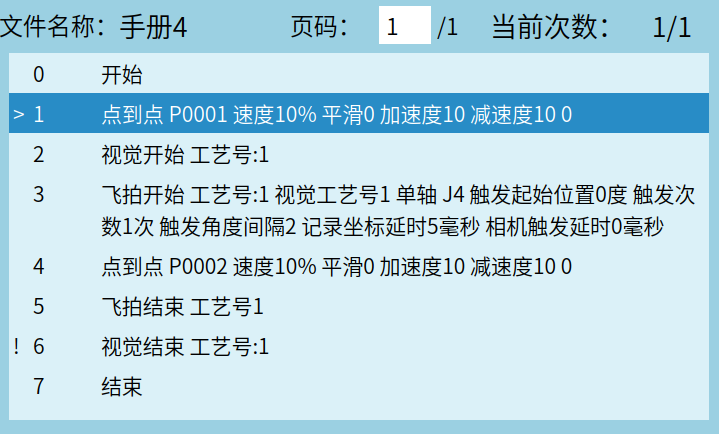
Example: Single axis.
Note: Trigger angle spacing positive number is positive direction, negative number is negative direction.\ Single axis method, J4, motion trajectory from -44 to 44, start position 0, trigger count 3, trigger angle spacing 5, means when triggered at 0, next trigger point is 5, next is 10, will trigger three times.\ Single axis method, J4, motion trajectory from -44 to 44, start position 0, trigger count 3, trigger angle spacing -5, means when triggered at 0, next trigger point is -5, next is -10, will only trigger once, because motion trajectory from -44 to 44 is positive direction motion.
Program Logic: During flying shot trajectory P001 to P002 motion, J4 axis passes 0° to trigger photo.
ONFLY_END - End Flying Shot
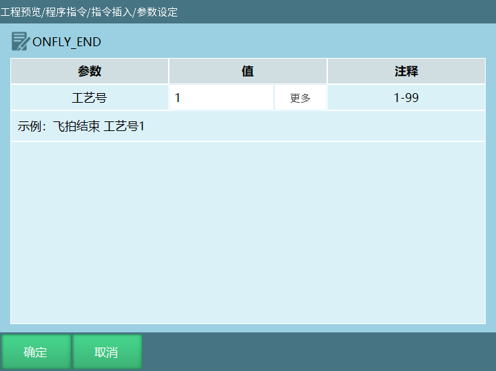
Format: ONFLY_END [Instruction Name] ID=1 [Process Number].
Function: End the flying shot task.
Can be used independently. Executing flying shot end before executing flying shot start is invalid.
Parameters:
| Parameter | Description |
|---|---|
| Process Number | Vision flying shot process number, range [1,99]. Supports manual process number and variable (INT,GINT) representation |
Description: Inserting flying shot end instruction alone will not cause errors when the program runs. Executing flying shot end before executing flying shot start is invalid.
ONFLY_GET_STATUS - Get Flying Shot Open Status
Format: ONFLY_GET_STATUS [Instruction Name] ID=2 [Flying Shot Process Number] STATUS=B001 [Status].
Function: Get whether the flying shot task is open, store the obtained status into the selected variable.
Parameters:
| Parameter | Description |
|---|---|
| Process Number | Vision flying shot process number, range [1,99]. Supports manual process number and variable (INT,GINT) representation |
| Result | Get the flying shot task open status, store the obtained status into variable (BOOL,GBOOL). "0" means flying shot is not open, "1" means flying shot is open. For example: selected variable is B001, execute get flying shot open status instruction. If flying shot is open then B001=1, if flying shot is not open then B001=0 |
ONFLY_CALC_TOOL - Flying Shot Calculate Tool Hand
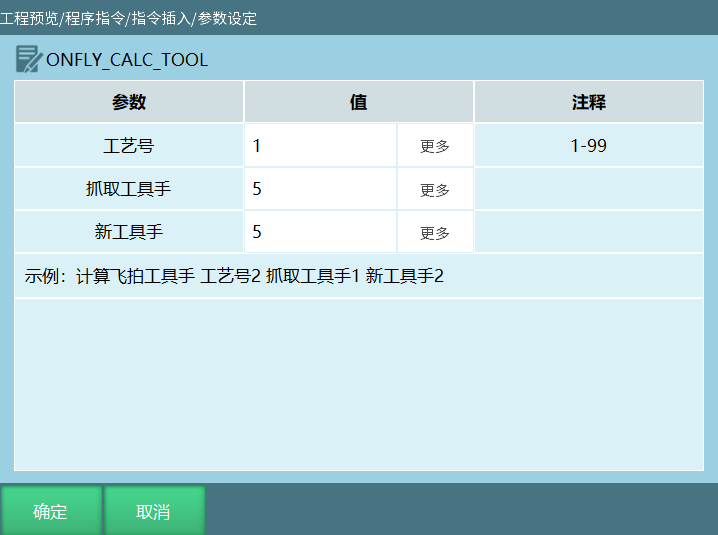
Format: ONFLY_CALC_TOOL [Instruction Name] ID=2 [] GRABTOOL=1 [Grasp Tool Hand] NEWTOOL=2 [New Tool Hand].
Function: Flying shot calculate tool hand is used when the robotic arm grips the workpiece and may have eccentric position, and the workpiece has rotation angle. After calculation and switching to the new tool hand, the workpiece center is placed at the material placement position point, without eccentricity or rotation.
Parameters:
| Parameter | Description |
|---|---|
| Process Number | Vision flying shot process number, range [1,99]. Supports manual process number and variable (INT,GINT) representation |
| Grasp Tool Hand | Supports manual tool hand number and variable (INT,GINT) representation, range [1,999]. The tool hand for grasp photo |
| New Tool Hand | Supports manual tool hand number and variable (INT,GINT) representation, range [1,999]. The new tool hand obtained through calculation |
Example: Single photo point calculate flying shot tool hand program writing.
Program Logic: Switch to tool hand 1, go to workpiece pickup point, grip workpiece and pass photo point, trigger camera to take photo and return position while controller records current position. Calculate flying shot tool hand instruction reads corresponding process number flying shot data to calculate new tool hand 2. Switch to tool hand 2, place workpiece center at material placement position point through offset, without eccentricity or rotation.
i. When robotic arm grips workpiece center, the calculated tool hand 2 should be consistent with tool hand 1;
ii. When robotic arm grips workpiece eccentric position, workpiece has no rotation. After calculation and switching to tool hand 2, workpiece center is placed at material placement position point, without eccentricity;
iii. When robotic arm grips workpiece eccentric position, workpiece has rotation angle. After calculation and switching to tool hand 2, workpiece center is placed at material placement position point, without eccentricity or rotation.
Note: When executing calculate flying shot tool hand, if the camera hasn't returned position yet, it will report: Tool hand calculation error.
The following positions need to be in the job file variable interface, select tool, write current position, otherwise it will execute without tool hand. P0004 point tool hand needs to be manually filled with 0.
NOP
SWITCHTOOL (1) #Switch to the above calibrated tool hand
MOVJ P0001 VJ = 80% PL = 0 ACC = 80 DEC = 80 0 #Workpiece pickup point
VISION_RUN ID = 1 #Start Vision
ONFLY_INIT ID = 1 VISIONID = 1 TYPE = Point GP0001 RADIUS = 1 DELAY = 1.9 CAMERA_TRIGGER_DELAY = 0 #Start flying shot, trigger method photo point GP0001 radius 1 record delay 1.9 camera delay 0
MOVL P0002 V = 1000 mm/s PL = 0 ACC = 100 DEC = 100 0 #Flying shot motion trajectory start point
MOVL P0003 V = 1000 mm/s PL = 0 ACC = 100 DEC = 100 0 #Flying shot motion trajectory end point
ONFLY_CALC_TOOL ID = 1 GRABTOOL = 1 NEWTOOL = 2 #Calculate flying shot tool hand Calculate new tool hand 2
SWITCHTOOL (2) #Switch to tool hand 2
MOVL P0004 V = 1000 mm/s PL = 0 ACC = 100 DEC = 100 0 #Workpiece center placed at material placement position point
ONFLY_END ID = 1 #End flying shot
VISION_END ID = 1 #End Vision
END
Vision Process Example Description
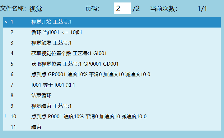
Example 1: After camera takes 10 photos, vision closes
Example 2: Camera sends positions as continuous trajectory
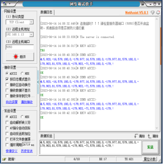
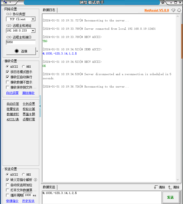
When the camera sends positions as continuous trajectory, you can get positions through the get trajectory position instruction. The following example uses network debugging assistant to send positions, vision communication is successful, send positions. The sent positions are only for illustration, no actual meaning.
- Get trajectory position, position storage location selects external point
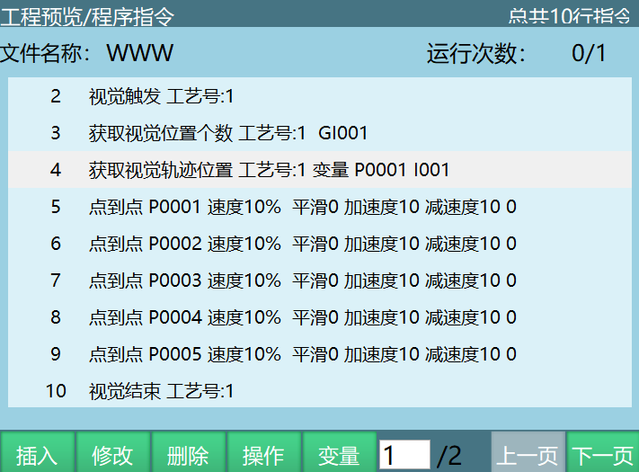
- Position storage location selects variable
For example: First variable selects P0001, network debugging assistant sends 5 positions, program as shown:
Example 3: Get tracking position additional data parameter description
- Vision process - vision parameter interface set additional data count, maximum supports 10.
- Click vision position parameter to enter parameter interface and view example format, "data" represents additional data.
- External device: network debugging assistant, send positions according to the example format in vision position parameter interface.
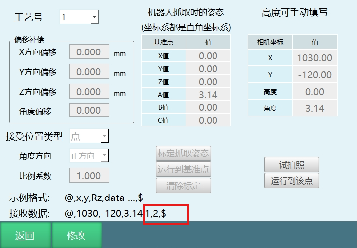
- Click test photo, after network assistant sends positions, the "1,2" in received data row represents additional data. Additional data defaults to store in GS001, stored sequentially according to defined additional data count.
- If inserting get conveyor belt tracking position instruction, executing the instruction will store the defined additional data values into the user's selected variables (integer, floating-point, string). Users can represent workpiece shape and color with numbers (for example GD001=1 represents red, GD002=2 represents green), then through conditional judgment track and grasp workpieces of different colors.
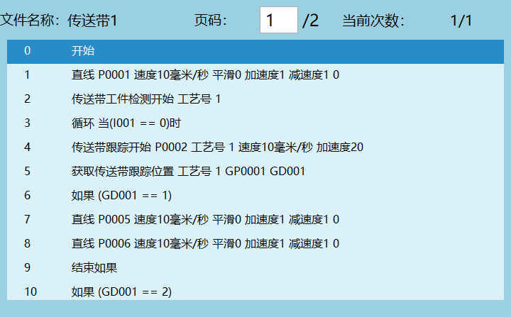
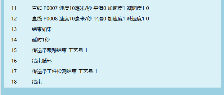
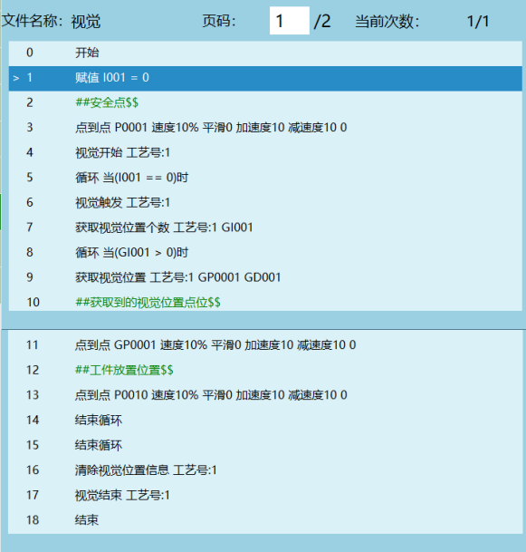
Example 4: After camera photographs material, send data to robot, robot goes to grasp
As shown:
Q&A for Retrieval
Q: What is the purpose of vision calibration?
A: The purpose of vision calibration is to calibrate the transformation relationship from the camera coordinate system to the robot coordinate system, thereby determining the position coordinates of the target identified by the camera in the robot coordinate system, and finally achieving robot movement to the target position.
Q: What are the two methods of vision calibration?
A: Vision calibration is mainly divided into two methods:
- Eye-in-Hand: Camera installed on tool hand, needs to calibrate 6-30 points, including at least 3 unchanged attitude positions and 3 changed attitude positions
- Eye-to-Hand: Camera fixedly installed, divided into three steps: 9-point (16-point) hand-eye calibration, tool hand calibration, high-precision tool hand calibration
Q: What is the flying shot function?
A: Flying shot function refers to when the robot tool hand moves past the photo point, quickly trigger the camera to take a photo. During the photo process, the object or camera is in motion.
Q: What are the flying shot trigger methods?
A: Flying shot trigger methods include:
- Photo Point: triggered when robot passes photo point
- IO Signal: triggered by rising edge or falling edge of IO signal
- Single Axis: trigger multiple photos by angle spacing
Q: What is the typical application scenario of vision process?
A: Typical application scenarios of vision process include:
- Industrial robot grasping workpieces
- Conveyor belt tracking grasping
- Precision positioning tasks
- Visual guidance in automated production lines
- Scenarios requiring precise identification and positioning
Q: What trigger methods does vision process support?
A: Vision process supports two trigger methods:
- IO Trigger: Give camera a trigger signal, need to set IO signal port and hardwire camera to corresponding IO
- Ethernet Trigger: Default through Ethernet to send "TRG" (or user-defined string) trigger. After camera receives, reply with controller coordinate values
Q: What data types does vision process support?
A: Vision process supports four data types:
- Robot coordinates: data sent by camera is robot's coordinates
- Pixel coordinates: data sent by camera is pixel coordinates under camera coordinate system
- Conveyor pixel coordinates: used for controller to do hand-eye calibration
- Conveyor robot coordinates: after camera completes hand-eye calibration, controller performs secondary calibration to increase data accuracy
Q: What is the purpose of offset compensation and scale factor in vision position parameters?
A: Offset compensation is used to correct the fixed direction deviation between robot grasp position and actual position; scale factor is used to restore the scaled position value sent by camera to actual position value. Calculation formula: Scale Factor = Actual Position Value / Camera Sent Position Value.
Q: What instructions does vision process support?
A: Vision process supported instructions include: VISION_RUN (Start Vision), VISION_TRG (Trigger Vision), VISION_POSNUM (Get Vision Position Count), VISION_POS (Get Vision Position), VISION_CLEAR (Clear Vision Position Info), VISION_END (End Vision), VISION_TRACE (Get Vision Trajectory Position).
Q: What instructions does flying shot function support?
A: Flying shot function supported instructions include: ONFLY_INIT (Start Flying Shot), ONFLY_END (End Flying Shot), ONFLY_GET_STATUS (Get Flying Shot Open Status), ONFLY_CALC_TOOL (Flying Shot Calculate Tool Hand).
Q: What is the process number range for vision process?
A: Vision process provides 1-99 process numbers. Each process number saves all vision parameters and vision position parameters under that process number.
Q: What are the camera target types for vision process?
A: Vision process supports three camera target types: 2D (sends X,Y,Rz), 2D+Height (sends X,Y,Rz,h), 3D (sends X,Y,Z,A,B,C).
Q: What is the purpose of additional data?
A: Additional data is used to store data sent by camera besides position (such as tool hand number, color, whether position is valid, etc.). User-defined additional data defaults to first variable GS001, stored sequentially according to additional data count.
Q: What is the purpose of vision range setting?
A: Vision range setting is used to avoid position parameters returned by camera exceeding the robot's reachable range. If camera returned data exceeds range, a warning will be given and data will be automatically filtered and not take effect.
Q: What content does the advanced parameters of vision process include?
A: Advanced parameters of vision process include: hand-eye calibration user coordinate system, target data contains tool hand info, target data contains user coordinate info, target attitude value is radians/degrees, local client port specification, trigger timeout.
Version History
| Version | Date | Author | Changes |
|---|---|---|---|
| 1.0.0 | 2026-06-29 | tongmengyuan123 | Initial version |