Teach Pendant Programming Guide
Power-On Safety Check
- Check that the servo, controller, and teach pendant connection cables are properly connected.
- Rotate the main power switch on the cabinet panel to the ON position to turn on the main power.
- Press the green servo start button on the cabinet panel.
- After the teach pendant starts successfully, confirm that the robot parameters are normal. After confirming no parameter issues, you can jog the robot.
Warning: To prevent robot runaway during motion, please confirm the emergency stop button is normal before teaching! |
Emergency Stop Button Confirmation
- Before using the robot, confirm the emergency stop buttons on the control cabinet and teach pendant. When pressed, check if servo power is disconnected.
- Press the emergency stop buttons on the control cabinet and teach pendant.
- Confirm servo power is off, teach pendant shows servo error, control cabinet servo error light is on.
- Clear servo error, control cabinet servo error light turns off, teach pendant displays "Servo Stop".
- Gently press the [DEADMAN] button (button on the back of the teach pendant), robot powers on, teach pendant displays "Servo Running", indicating servo power is successfully connected.
Robot Configuration Parameters
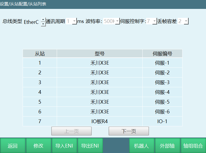
- After teach pendant starts successfully, in [Settings] - [Slave Configuration] - [Slave List] interface, confirm the number of connected slaves, slave models, and robot type.
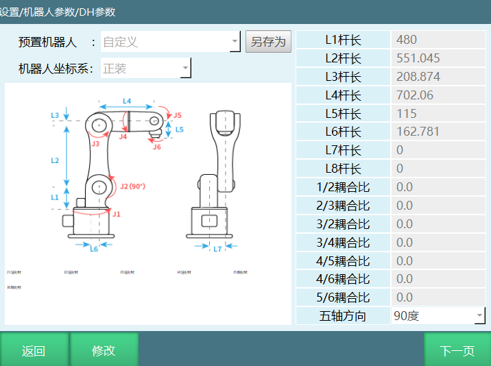
- In [Settings] - [Robot Parameters] - [DH Parameters] interface, confirm link lengths, coupling ratios and other parameters are correct.
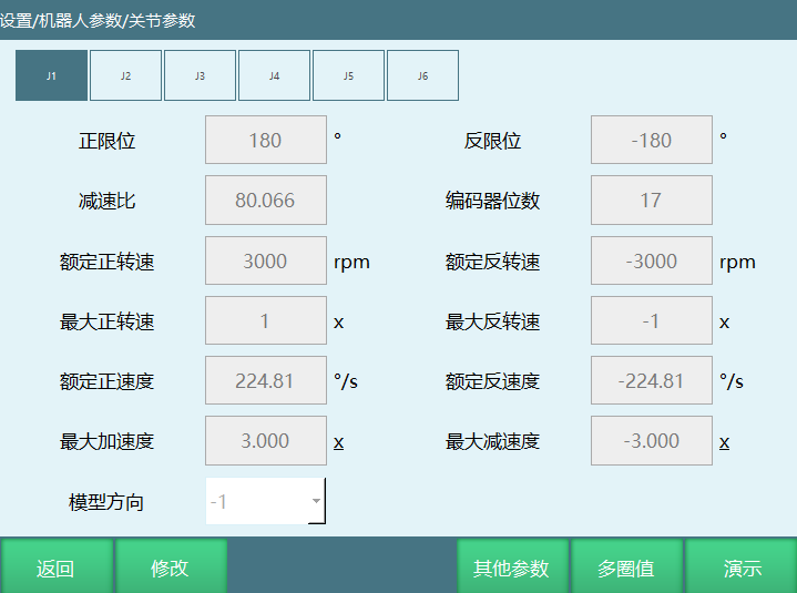
- In [Settings] - [Robot Parameters] - [Joint Parameters] interface, confirm joint parameters for each joint axis.
- If robot configuration parameters are not present after teach pendant starts, you need to re-import the configuration.
Import configuration process:
- Click [Settings] - [Robot Parameters] - [Robot Type] interface, set robot type
- Click [Settings] - [System Configuration] - [Import Controller Configuration] select configuration file. After system restart, robot parameter configuration is imported successfully
| Warning: The imported configuration file must be the configuration file for the currently selected robot. Incorrect configuration file will cause robot runaway when jogging |
After configuration file is imported successfully:
- Servo order:
According to servo connection order, jog the robot to check if servo slave 1 controls axis 1, servo slave 2 controls axis 2, and so on. If not, modify manually.
Note: Some servo slaves have multi-in-one configurations, so robot axes in slave configuration may not be in 1234567 order.
- Model direction:
When the actual jogging direction matches the robot model direction, model direction value remains unchanged.
When the actual jogging direction is opposite to the robot model direction, you need to negate the model direction value in the joint parameters interface.
- Zero position:
Click [Zero] on the teach pendant, robot runs to zero position. After robot returns to zero position, check if each axis position is at zero. If zero position has deviation, recalibrate zero.
Note: - If the actual jogged robot joint axis shows 90 degrees but the teach pendant doesn't display 90 degrees, adjust the reduction ratio or confirm with the manufacturer. - If jogging a coordinate axis in Cartesian coordinates causes the robot to not move straight, adjust DH parameters or contact the manufacturer. |
Jogging Robot Operation
Teach pendant and controller are connected normally.
Servo and robot parameters are normal.
In teach mode, press the [Servo] button on the teach pendant to switch servo from stopped state to servo ready.
Gently press the [DEADMAN] button (button on the back of the teach pendant), hold it down. You will hear the robot powering on sound, and the "Servo Status" column shows green "Servo Running".
Control robot motion through the physical buttons on the right side of the teach pendant.
Project Interface Operation
Switch user permission to administrator or create a new user with custom permissions. How to customize permissions can be found in the "Teach Pendant Function Keys" manual.
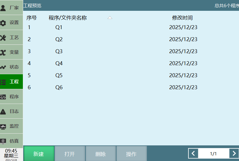
Click [Project] on the left to enter the project preview interface.
New
New Folder
Click [Project] to enter the project interface.
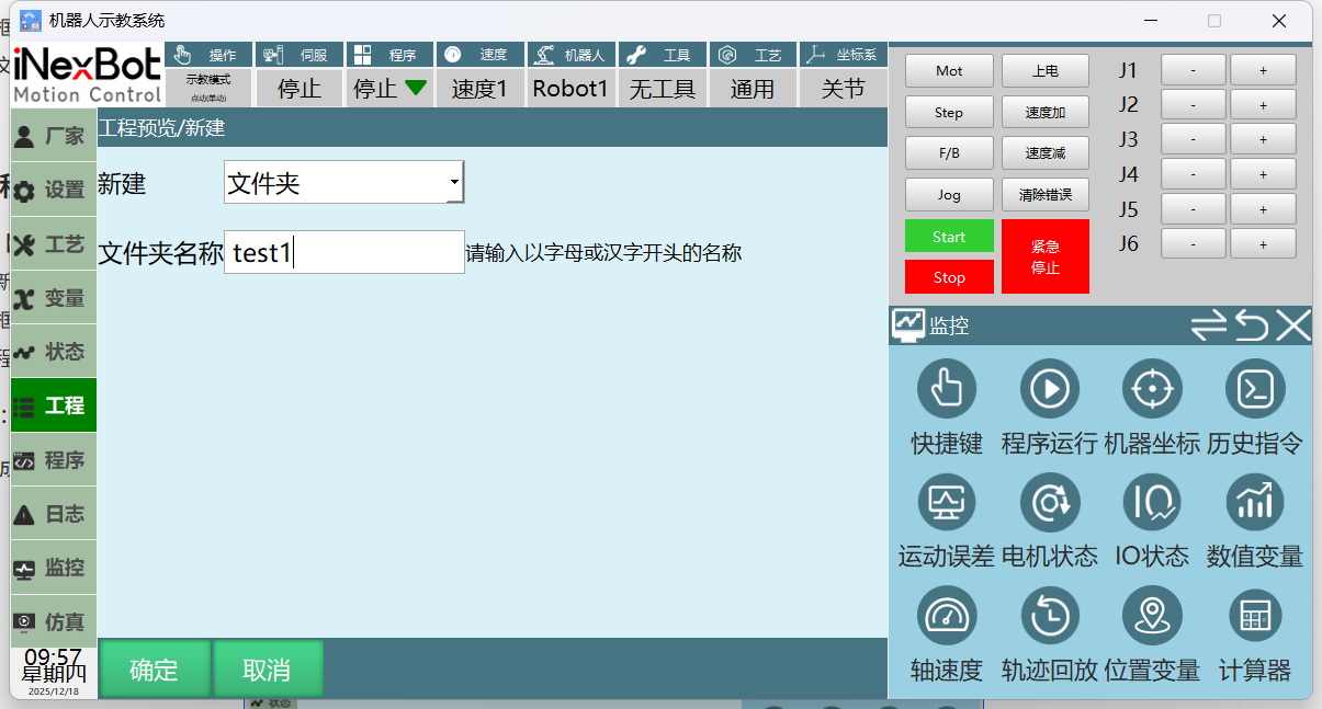
Click New to enter the new interface.
Select Folder from the dropdown.
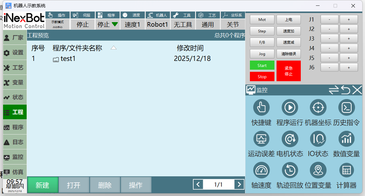
Enter folder name and click the [OK] button at the bottom. Folder is created successfully. A folder icon will appear before the name to distinguish it from programs. To cancel creating a folder, click [Cancel].
Notes: Folder name must be a string of 2 or more characters starting with a letter/Chinese character. New folder name cannot be an existing folder name. Folder name cannot exceed 30 characters.
New Project
Click [Project] to enter the project interface.
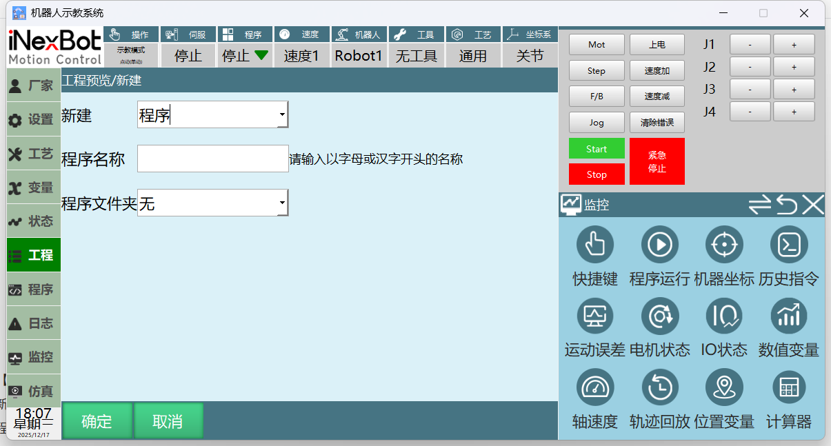
Click New to enter the new interface.
Select Program from the dropdown. If you want to create the program in a folder, select from the program folder dropdown.
Enter program name and click the [OK] button at the bottom. Program is created successfully and jumps to the program instruction interface. To cancel creating a program, click [Cancel].
Notes: Program name must be a string of 2 or more characters starting with a letter/Chinese character. New program name cannot be an existing program name. Program name cannot exceed 30 characters.
After program is created successfully, the new program name will appear in the project interface.
Open
Click [Project] to enter the project preview interface.
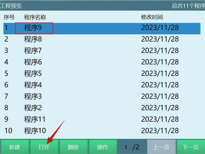
Select the program or folder you want to open.
Click the [Open] button at the bottom. Program is opened successfully.
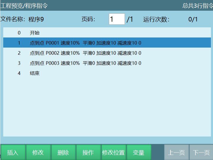
Delete
Click [Project] to enter the project preview interface.
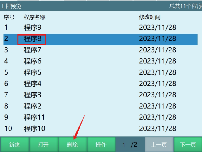
Select the program or folder to delete.
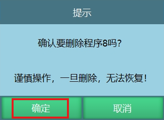
Click the [Delete] button at the bottom. Click [OK] in the prompt interface to delete the program. Click [Cancel] to cancel the delete operation.
Operations
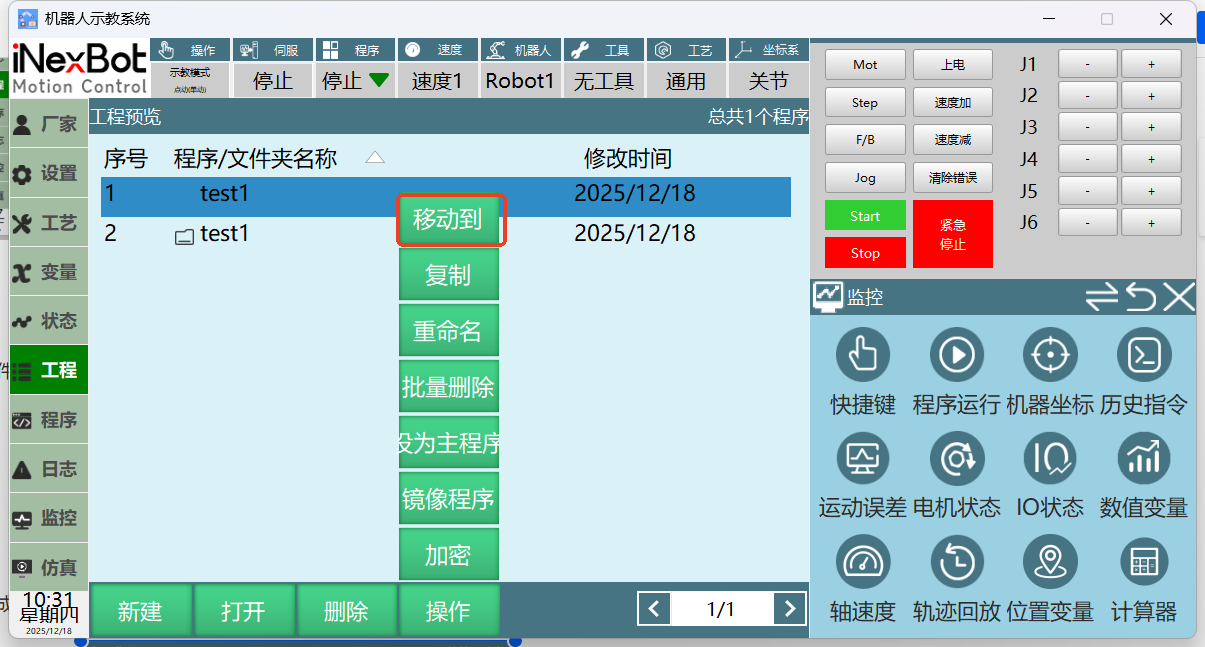
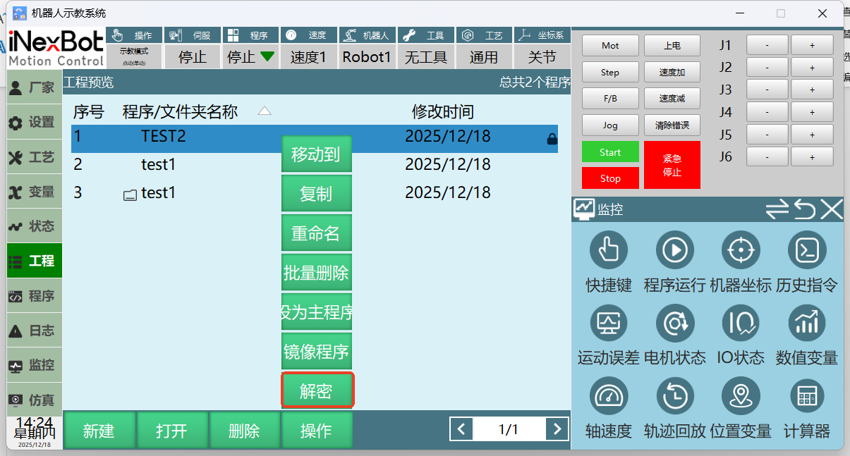
Click the Operations button to perform move, copy, rename, batch delete, set as main program, mirror program, and encrypt operations on the program.
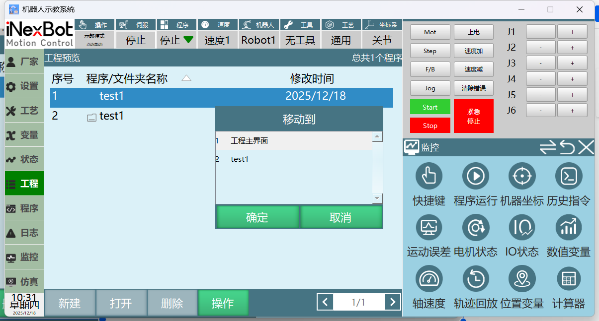
- Move
Select program, click Operations, click Move To
Select project main interface or any folder
Click OK to move to program main interface or any folder. Click Cancel to not move
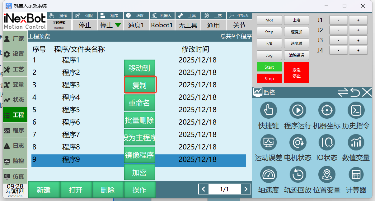
- Copy: Copy an existing program, supporting users to backup the original program before modifying it.
Enter [Project] interface.
Select the program to copy.
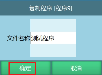
Click the [Operations] button at the bottom, select [Copy]. Click [OK] in the copy program prompt to copy successfully. Click [Cancel] to cancel the copy operation. The copied program name can also be modified.
After copying successfully, the copied program will be displayed in the project interface.
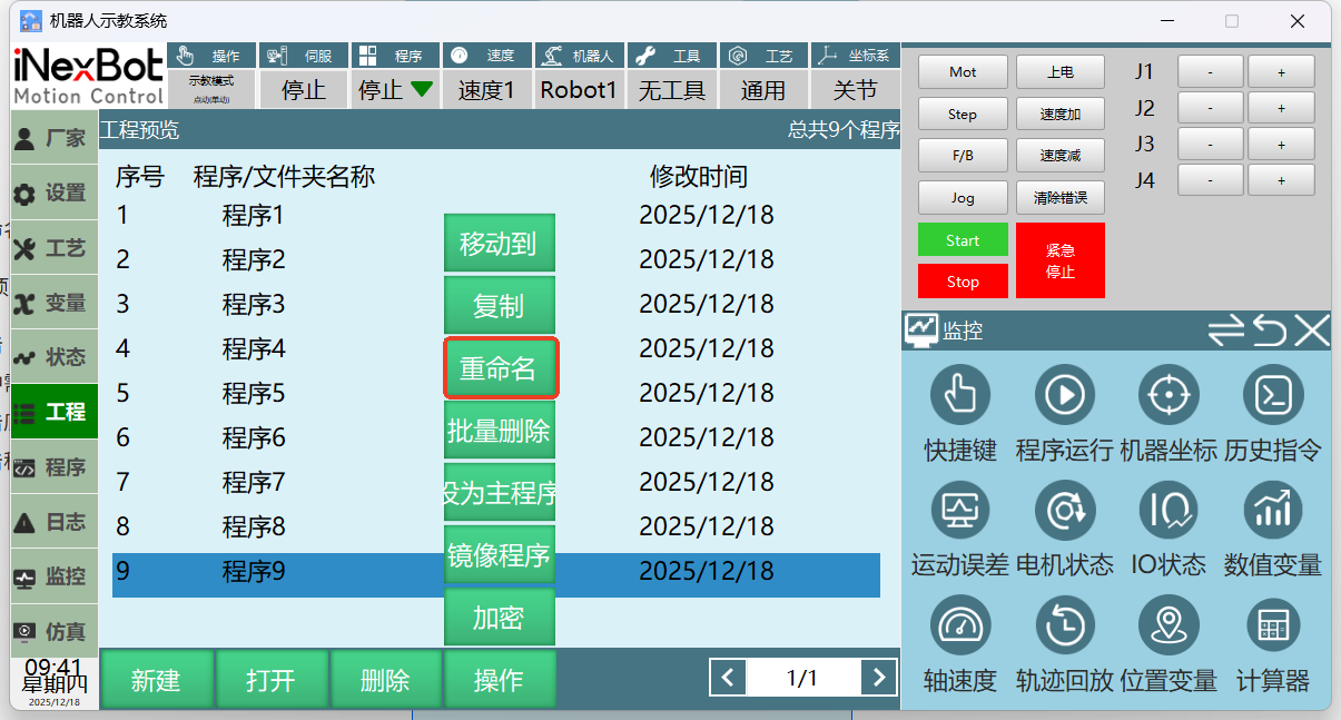
- Rename: Rename the selected original program
Notes: Renamed program name cannot be an existing program name. Foreground and background program names cannot be duplicated.
Click [Project] to enter the project interface
Select the program to rename
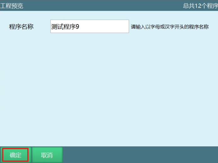
Click the [Operations] button at the bottom, select [Rename]. Rename the program in the project preview interface
Click [OK] in the program preview interface. Program is renamed successfully. Original "Program 9" is renamed to "Test Program 9". Click [Cancel] to cancel the rename operation
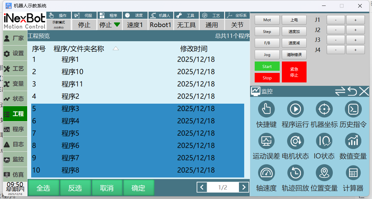
- Batch Delete: Delete multiple programs at once. Batch select can only select programs on the current page, cannot delete programs from previous or next pages.
Click [Project] to enter the project interface.
Click the [Operations] button at the bottom, select [Batch Delete].
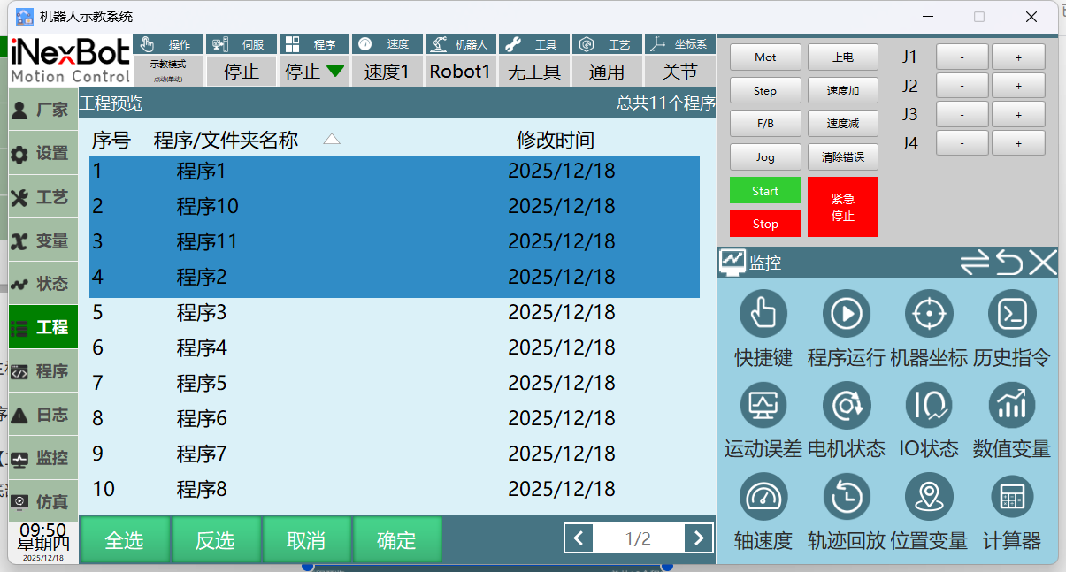
[Select All]: Select all programs on the current page. To delete some programs on the current page, directly click the programs or use the scroll wheel on the right side of the teach pendant to select programs.
[Invert Selection]: As shown below, if currently selected programs are Program 9, 8, 7, 6, 5, 4, clicking Invert Selection will select Program 3, 2, 11, 10.
[Cancel]: Cancel the batch delete operation.
[OK]: After clicking OK, click [OK] in the popup prompt to delete selected programs. Click [Cancel] to exit batch delete.
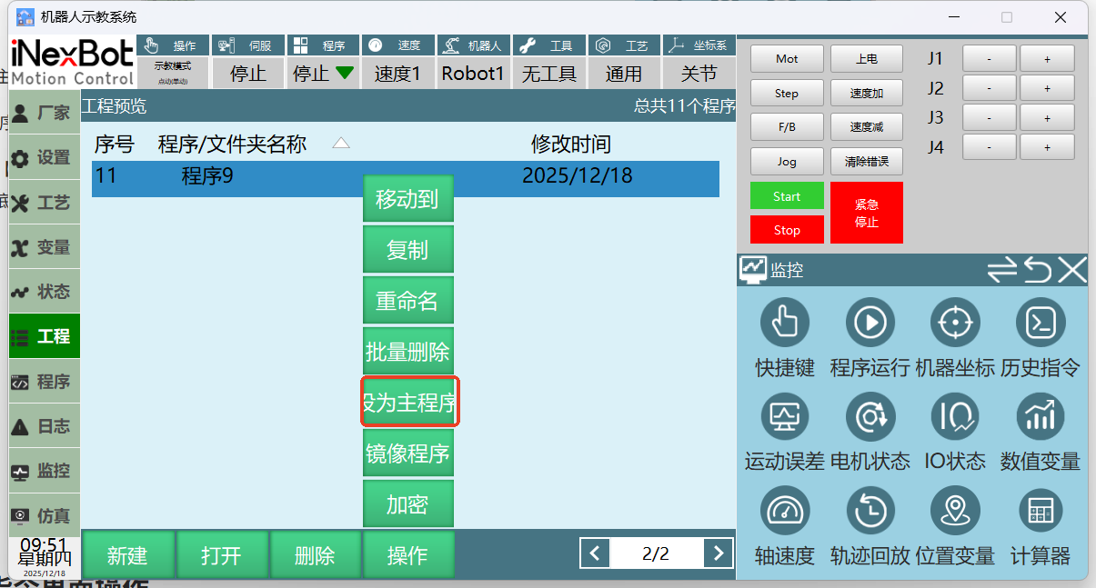
- Set as Main Program.
If you have inserted many call subroutine instructions in the program, setting as main program helps users identify which program is the main program when running.
Click [Project] to enter the project interface, select the program.
Click the [Operations] button at the bottom, select [Set as Main Program]. The program set as main program will have a "*" before its name.
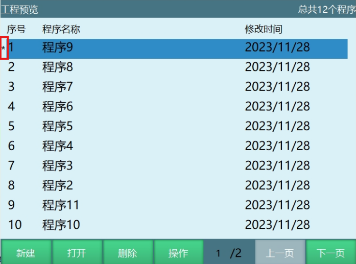
- Mirror Program (Only supports 6-axis serial robots)
Select a program
Click Operations, select Mirror Program
Select line numbers to mirror, target robot number, target job file name, coordinate system after mirroring. For Cartesian, select the reference plane for mirror conversion. For user coordinates, select the conversion offset compensation
Click OK to complete mirroring
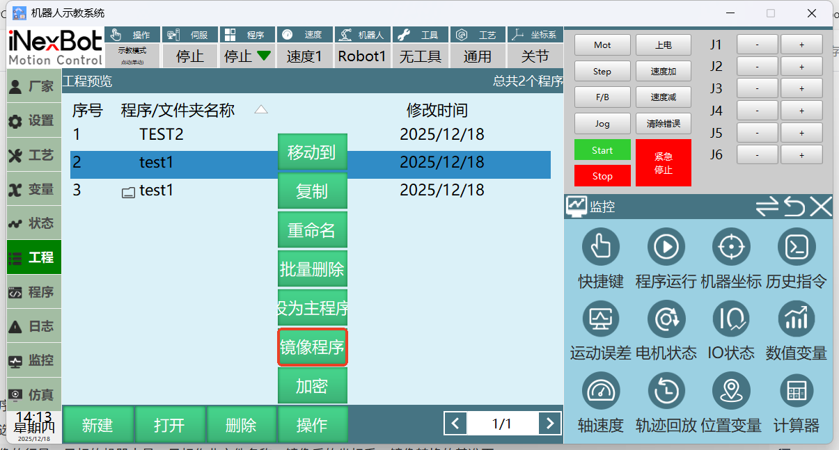
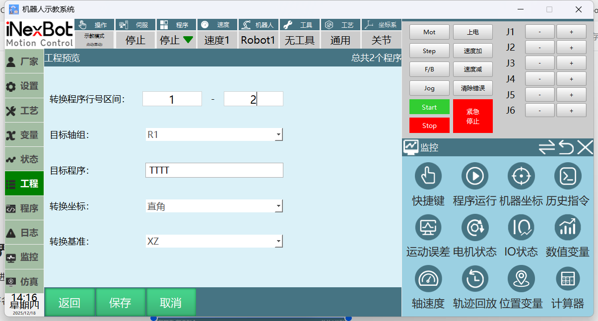
Mirror program parameter description:
Conversion program line number range: Mirror the selected line number points
Target axis group: When multiple robots are present, program can be mirrored to other robots
Target program: Job file name created after mirroring
Conversion coordinates: Point coordinates after mirroring
Conversion reference: Cartesian coordinates mirrored by XZ plane
- Encrypt/Decrypt
Select program, click Operations, click Encrypt
Encrypted programs allow viewing but not operations (modify, delete, copy, etc.), with a lock icon on the far right
Select encrypted job file, click Operations, click Decrypt to complete decryption (after decryption, program resumes modifiable operations)
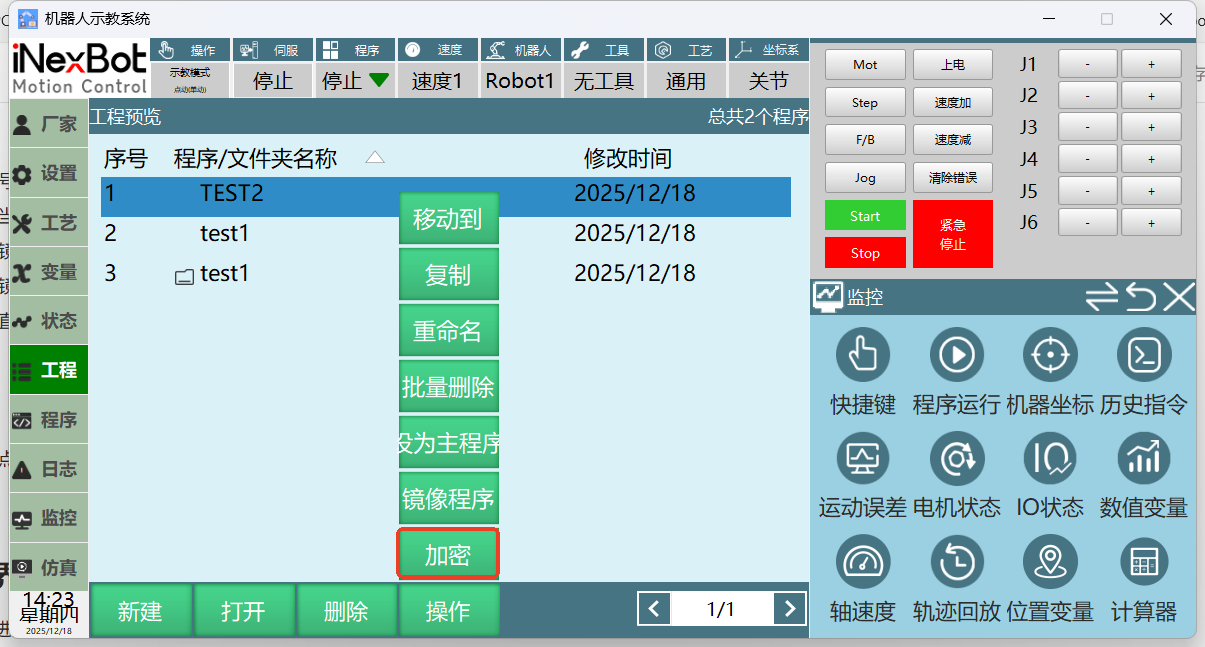
Program Instruction Interface Operation
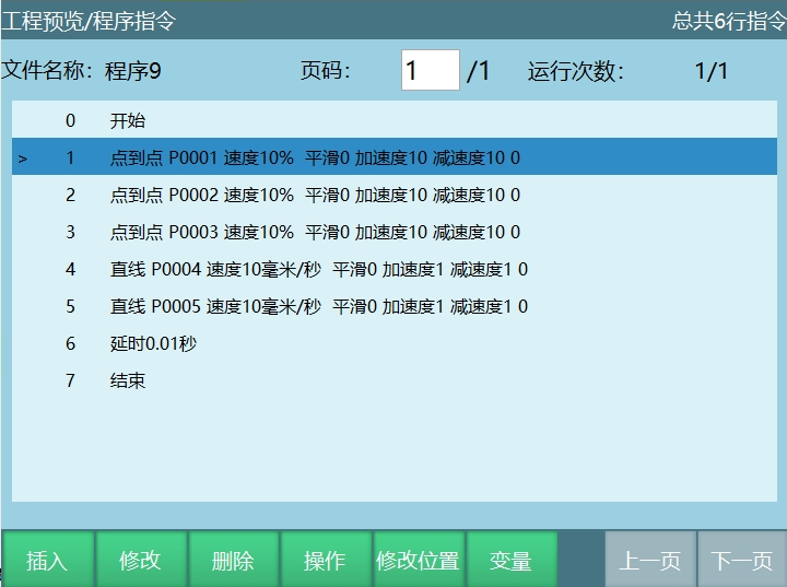
Click [Project] to enter the project preview interface.
Select the target program, click [Open] to enter the program instruction interface.
Insert Instruction
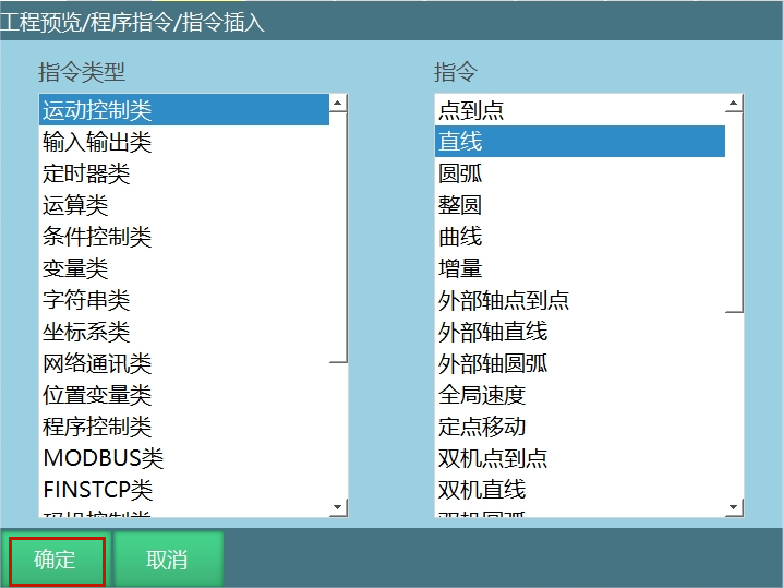
In the program instruction interface, click [Insert] to enter the instruction insertion interface.
Select the instruction type to insert, then select the instruction.
For example: Motion Control - Linear instruction.
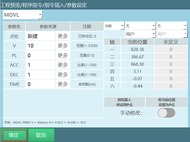
Click [OK] to enter the instruction parameter setting interface.
In the parameter setting interface, click [OK] to insert the instruction successfully.
Steps for inserting other instruction types are the same.
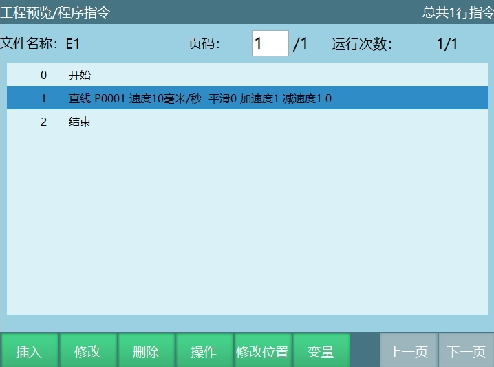
Modify Instruction
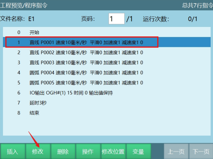
- In the program instruction interface, select the instruction to modify, click [Modify] to enter the parameter setting interface.
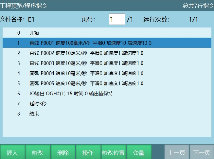
For example: To modify the selected linear instruction speed to 100mm/s, modify the instruction speed in the speed row of the parameter setting interface.
- After modifying parameters, click [OK] to modify the instruction parameters successfully.
Delete Instruction
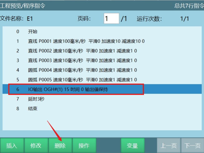
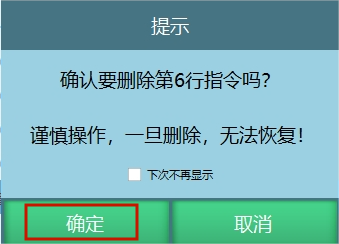
In the program instruction interface, select the instruction to delete, click [Delete].
Click [OK] in the prompt to delete the selected instruction. Click [Cancel] to cancel the delete operation.
Operations
- [Copy]
In the program instruction interface, select the instruction to copy, click [Operations], select [Copy].
Click [Paste] to paste the copied instruction to the target position.
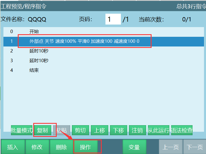
[Paste]: Paste the copied or cut instruction to the target position.
[Cut]
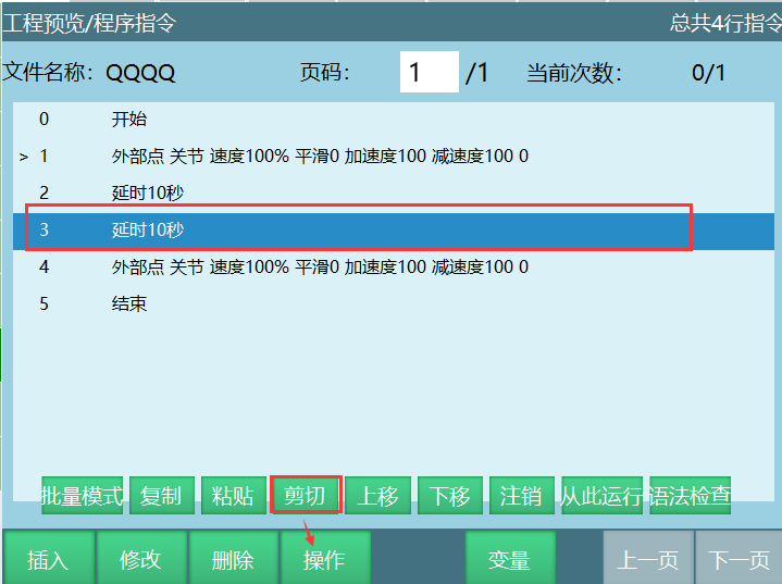
Select the instruction to cut, click [Operations], select [Cut].
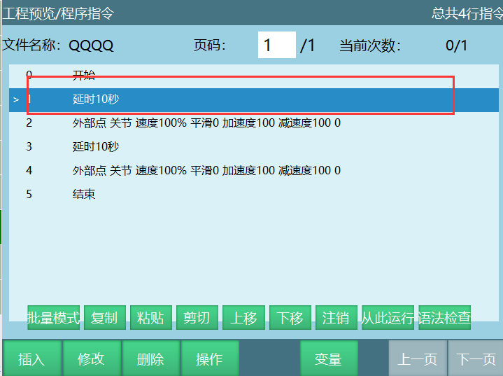
Click [Paste] to paste the copied instruction to the target position.
As shown below, cut the line 3 instruction and paste it to line 1 of the current job file.
[Move Up]: Click Move Up to move the selected instruction up one line.
[Move Down]: Click Move Down to move the selected instruction down one line.
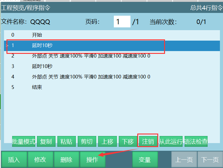
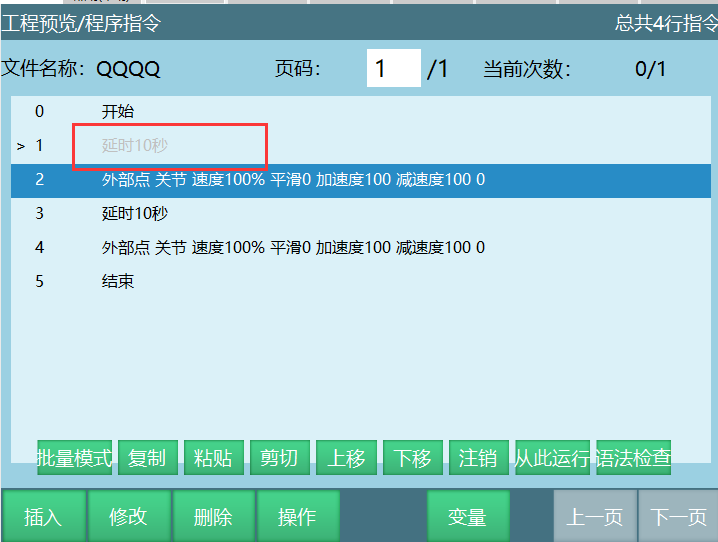
[Deactivate]
Select the instruction to deactivate, click [Operations], select [Deactivate].
Click [Deactivate] to deactivate the selected instruction. Deactivated instructions are skipped during execution.
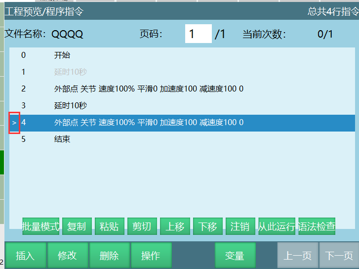
- [Run From Here]: When running the program, it starts from the set line number. Specific operation:
Select instruction, click [Operations], select [Run From Here].
Click [Run From Here], cursor appears before the selected instruction number.
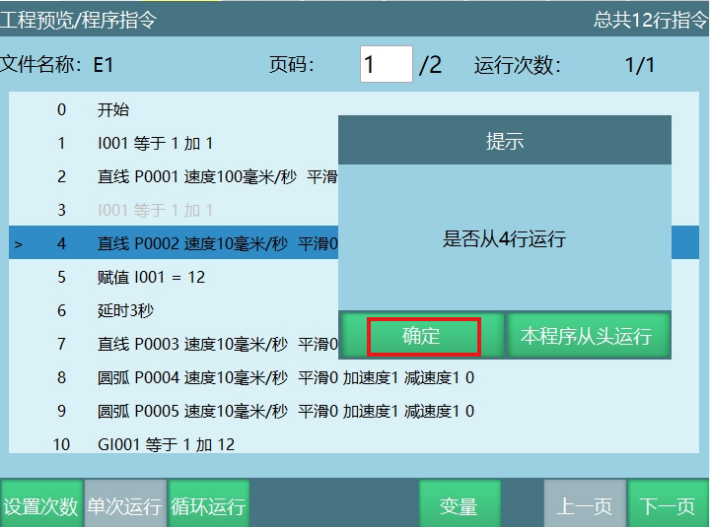
As shown below, when running this job file, the prompt asks if to start from line 4. Click [OK] to start from line 4.

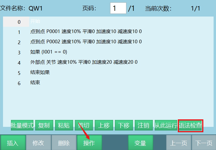
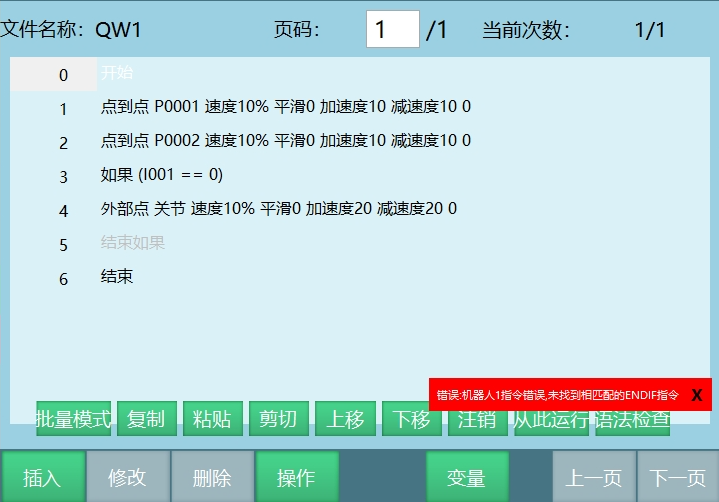
- [Syntax Check]: After inserting instructions, check for syntax errors
- Click [Operations], select [Syntax Check]. If instructions have syntax issues, the controller reports errors
Batch Mode Operations
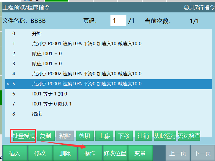
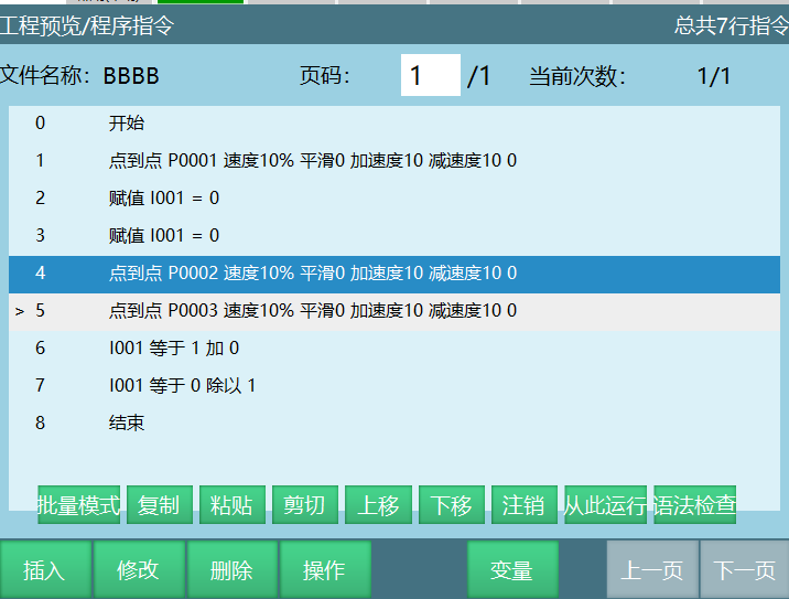
Perform copy, paste, cut, delete, modify, deactivate, move up, move down operations on multiple instructions simultaneously. Below are examples of batch copy and batch modify.
Batch Copy
Steps:
Click [Project] to enter the project preview interface.
Open the program to copy.
Click [Operations] - [Batch Mode] at the bottom to enter batch mode.
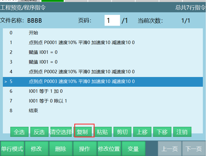
Select multiple instructions to copy.
Select [Copy] button.
Select the instruction above the paste position. For example, to paste copied instructions to line 5, select line 4 instruction.
Click [Paste] button.
Batch Modify
Steps:
Click [Project] to enter the project preview interface.
Click [Operations] - [Batch Mode] at the bottom to enter batch mode.
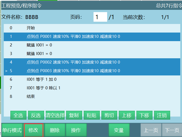
Select multiple instructions to modify.
Select [Modify] at the bottom to enter the batch modify interface.
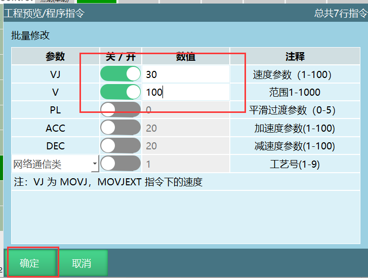
If any parameter needs modification, remember to turn on the corresponding enable switch and enter the modified parameter value.
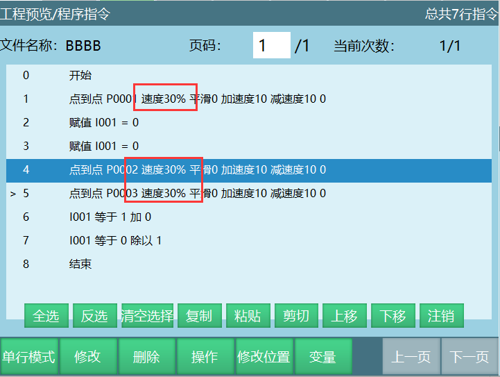
Click [OK] in the batch modify interface to modify selected instruction parameters successfully.
Cross-Job File Instruction Operations
Copy or cut instructions from the current file and paste them to another job file.
Using batch copy as example:
Click [Project] to enter the project preview interface.
Open the program to copy.
Click [Operations] - [Batch Mode] at the bottom to enter batch mode.
Select multiple instructions to copy.
Select [Copy] button.
Click [Project] to open the target job file.
Select the paste position. To paste copied instructions to line 4, select line 3 instruction.
Click [Paste] button. As shown, line 1 and line 2 instructions from program BBB are copied and pasted to CCC.
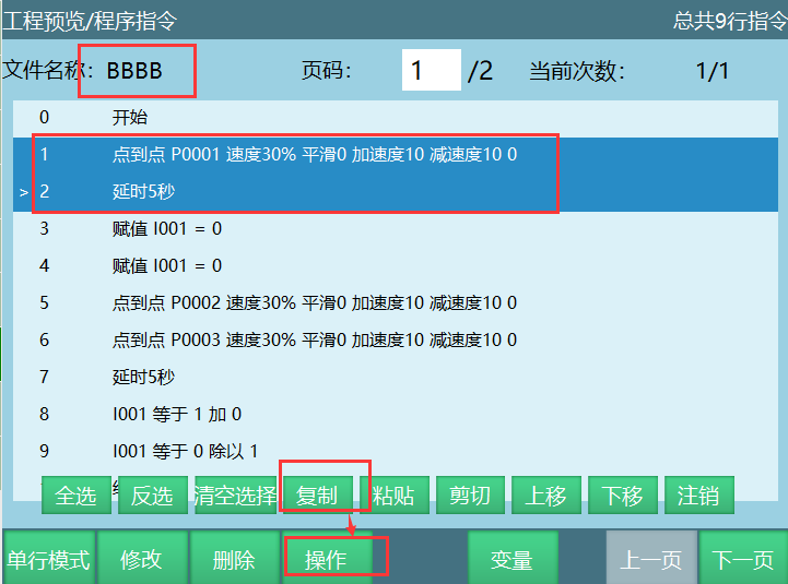
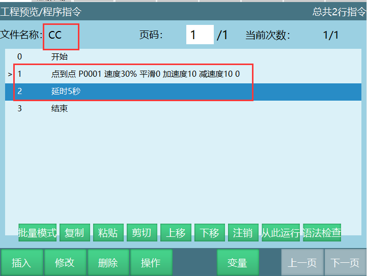
| Note - Foreground program instructions cannot be copied to background programs. |
Modify Position
Modify Position: Click Modify Position to store the robot's current actual position into the selected target position. Only when the selected instruction is a P, GP, E, GE position variable can position be modified.
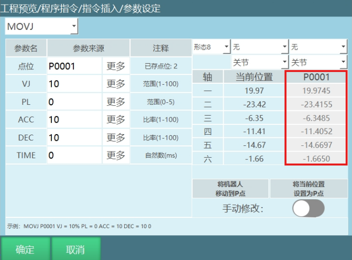
As shown: Program 2 has P0001 joint position (10,11,12,13,14,15).
Robot current position (19.97,-23.42,-6.35,-11.41,-14.67,-1.66).
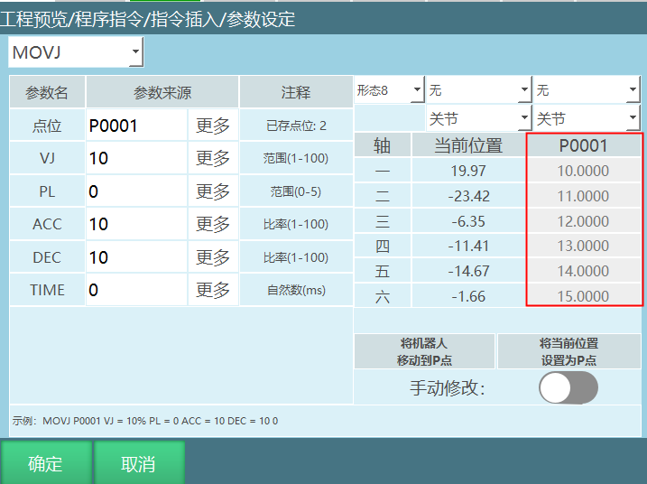
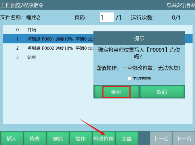
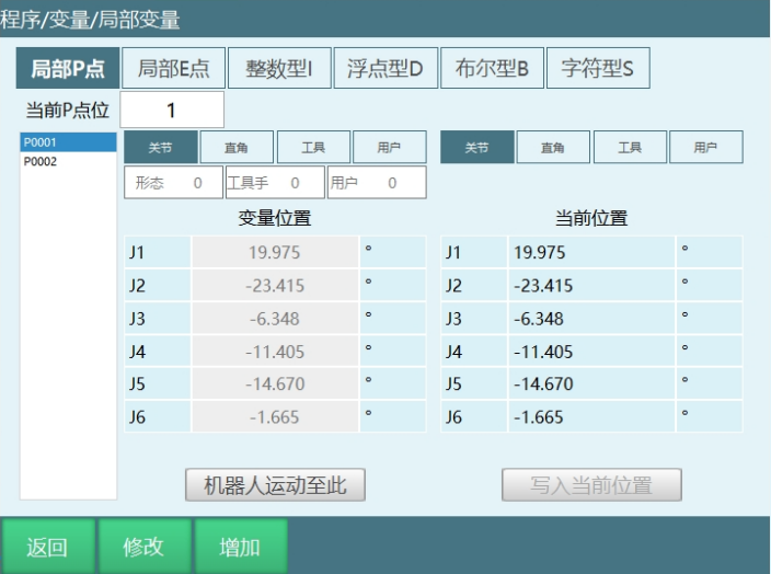
Click [Modify Position], then click [OK] in the prompt to write the robot's current position to variable P0001. As shown, P0001's position is modified to the robot's current position.
Click [Cancel] to cancel the position modification operation.
Variables
In the program instruction interface, click [Variables] to enter the local position variable interface. For local position variable introduction, refer to the "Variables Manual".
Teach Mode Operation
Users can switch between three modes ("Teach Mode", "Run Mode", "Remote Mode") using the [Mode Selection Key] in the upper right corner of the teach pendant.
In teach mode, you can complete robot system parameter setting, jogging operations, job file programming, and other operations.
Single Step Run
Click [Project], open the program to run, enter the program instruction interface.
Select the instruction line for single step operation.
Press [DEADMAN] button, robot powers on.
Press [Single Step] button, robot executes the selected line instruction, stops after execution.
Selected line automatically moves down/up. To single step the next instruction, press [Single Step] again.
- Forward execution:
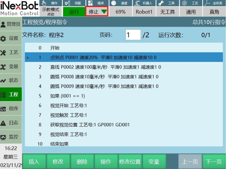
As shown below, click [Single Step] to run from line 1. After line 1 completes, automatically jump to line 2. Click [Single Step] to run line 2 instruction, and so on until the entire job file is complete.
- Reverse execution:
As shown below, click [Single Step] to run from line 4. After line 4 completes, automatically jump to line 3. Click [Single Step] to run line 3 instruction. After line 1 instruction completes, the entire job file execution ends.
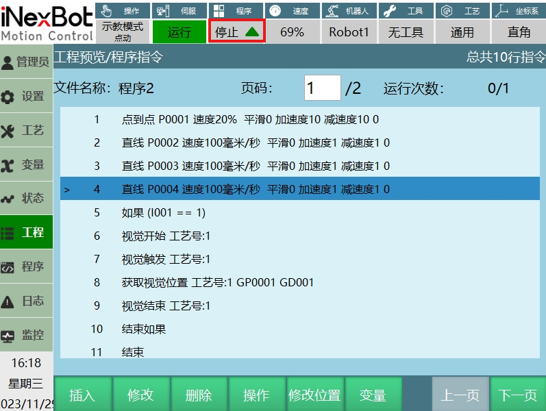
| Note: - Click below the teach pendant.  Button to switch between forward and reverse execution. |
Trial Run
Trial run function uses the [Start] key as the trial run button in teach mode. Power on, hold [Start] to keep running, release to stop.
Trial run mode supports all instructions.
Trial run does not support reverse execution or background programs.
As shown below, continuously pressing [DEADMAN] and [Start] buttons will run all instructions in the job file.
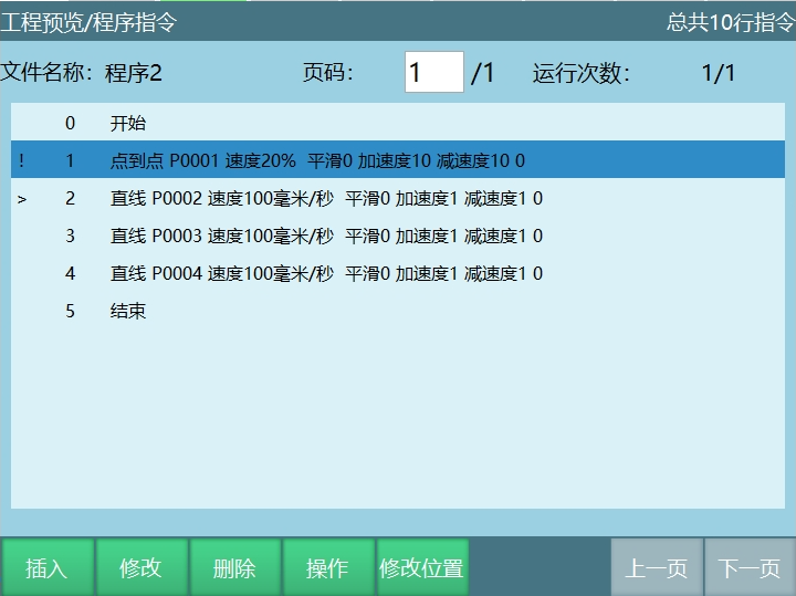
Teach Mode Speed
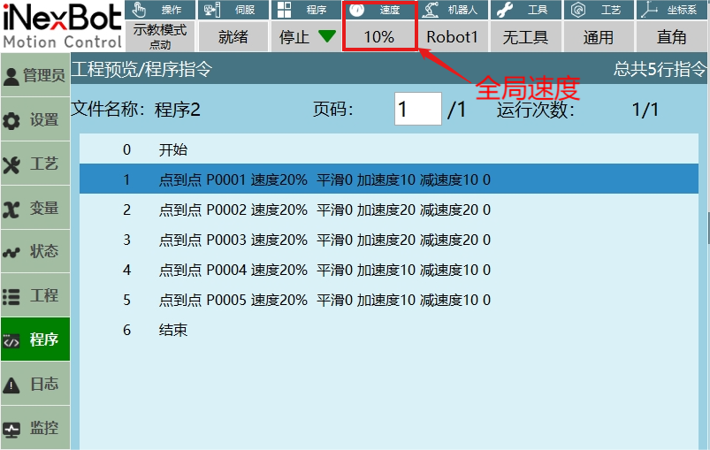
Description: Global speed here refers to the speed shown on the teach pendant status bar.
| Parameter | Description |
|---|---|
| Jog Speed (Teach Speed) | Joint jog speed Maximum joint axis jog speed * Global speed Modify maximum joint axis jog speed in Settings - Motion Parameters - Jog Speed interface |
| Jog Speed (Teach Speed) | Cartesian jog speed Maximum Cartesian axis jog speed * Global speed Modify maximum Cartesian axis jog speed in Settings - Motion Parameters - Jog Speed interface |
| Single Step Instruction Speed | Single step joint speed Global speed * Instruction speed * Joint rated forward speed Maximum speed limit: Joint rated forward speed * 30% |
| Single Step Instruction Speed | Single step Cartesian speed Global speed * Instruction speed Maximum limit: 300mm/s |
| Trial Run Speed | Same as single step instruction speed |
| Reverse Speed | Same as single step instruction speed |
| Return to Zero Speed | Teach speed |
Example:
- Single step joint speed
As shown, single step point-to-point instruction joint speed = Joint rated forward speed * Instruction speed 20% * Global speed 10%
- Jog joint speed
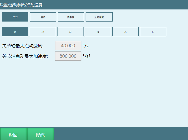
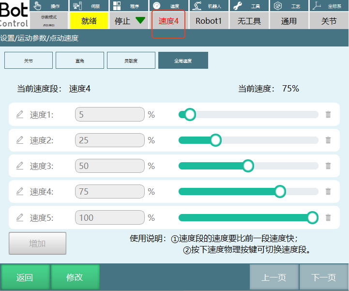
As shown, actual jog speed = 40°/s * 75% = 30°/s
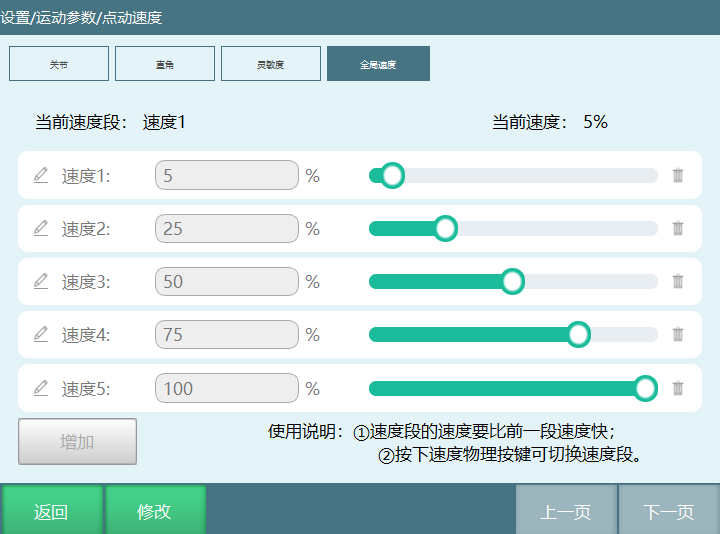
Global Speed Segmentation
Teach mode global speed
Speed segments can be individually named and set
Each segment speed increases sequentially, previous segment speed must be less than next segment speed
When the last segment speed is below 100, new speed segments can be added
Run Mode Operation
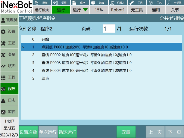
After job file programming in teach mode, rotate the knob in the upper right of the teach pendant to the center. Operation mode switches to run mode. Press [Start] on the teach pendant to start running the job file.
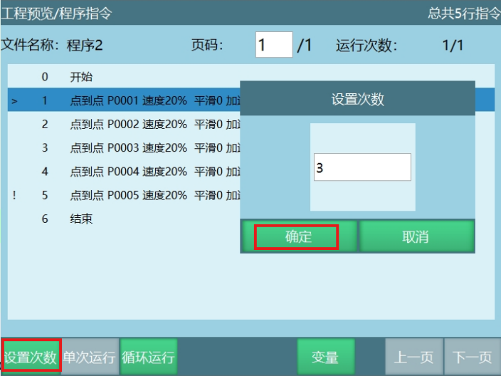
[Set Count]: Set the run count for the current job file. Run count can be modified while the program is running.
As shown, click [Set Count], set the run count and click [OK]. Program run count is set to 3. Click [Cancel] to cancel setting the count.
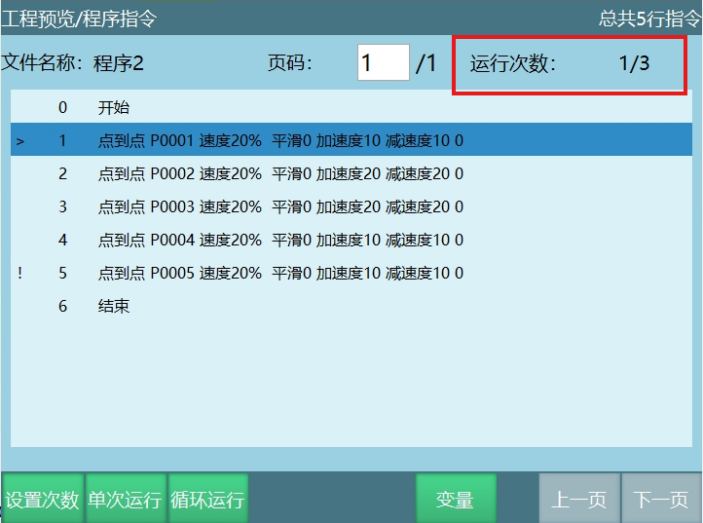
In run mode, the run count format displayed above the program is: Completed runs / Total set runs.
[Single Run]: Program runs once.
[Loop Run]: Click Loop Run, program runs in infinite loop.
[Variables]: Click Variables to enter the local position variable interface. In run mode, parameters in the local variable interface cannot be modified.
Run Mode Speed
Run mode default startup speed is 5%. To modify the default speed, modify in Settings - Operation Parameters interface, as shown below.
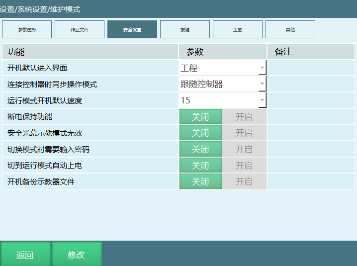
How to calculate run mode speed?
| Parameter | Description |
|---|---|
| Run Mode | Joint: Maximum axis speed = Rated forward speed * Instruction speed * Global speed (status bar speed) Cartesian: Maximum linear speed = Instruction speed * Global speed (status bar speed) Curve: First curve speed is used as trajectory speed |
Acceleration Parameter
The larger the acceleration multiplier, the faster the robot reaches maximum acceleration.
- Modify acceleration parameter for point-to-point instruction
Enter [Settings - Robot Parameters - Joint Parameters] to adjust maximum acceleration parameter
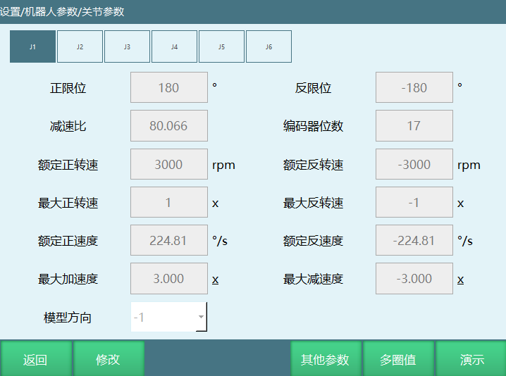
- Maximum axis speed = Rated speed * Global speed * Instruction speed
Example: Point-to-point instruction, global speed 50%, instruction speed 40%, instruction acceleration 10%, rated speed 200°/s, maximum acceleration 4x.
Maximum axis speed = 200°/s * 50% * 40% = 40°/s
Time to reach rated speed = (Rated speed * Global speed * Instruction speed) / (Rated speed * Maximum acceleration * Global speed * Instruction acceleration) = (200°/s * 50% * 40%) / (200°/s * 4 * 50% * 10%) = 1s
- Modify maximum acceleration parameter for linear instruction
Enter [Settings - Motion Parameters - General Motion Parameters] to adjust maximum acceleration parameter
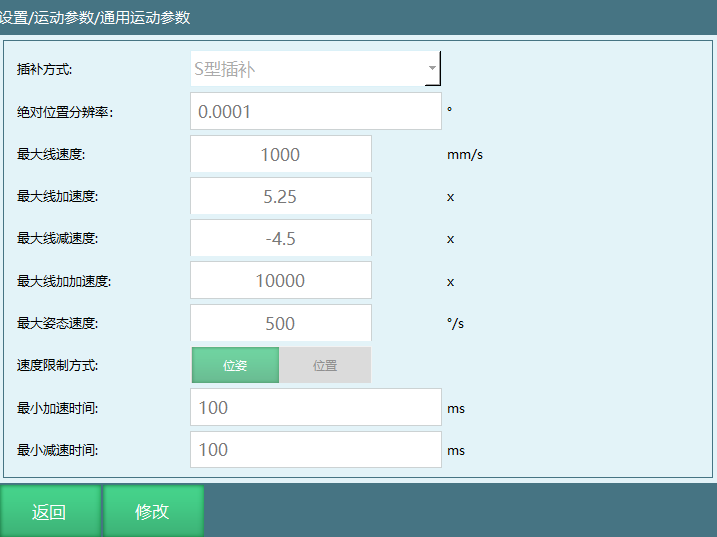
- Maximum linear speed = Global speed * Instruction speed
Example: Linear instruction, global speed 30%, instruction speed 1000mm/s, instruction acceleration 50%, maximum linear speed 2000mm/s, maximum linear acceleration 2x.
Maximum linear speed = Global speed * Instruction speed = 30% * 1000mm/s = 300mm/s
Time to reach rated speed = (Global speed * Instruction speed) / (Cartesian max speed * Cartesian max acceleration * Instruction acceleration * Global speed) = (30% * 1000mm/s) / (2000mm/s * 2 * 50% * 30%) = 0.5s
- Calculate rated forward speed from maximum forward rotation speed and reduction ratio.
Rated forward speed = Rated forward rotation speed * 360 / 60 / Reduction ratio.
Current Line Run
Main Program Set Current Line
- In teach mode, open the job file, select the instruction for current line run, click [Operations], select [Run From Here]. A > symbol appears on the selected line.
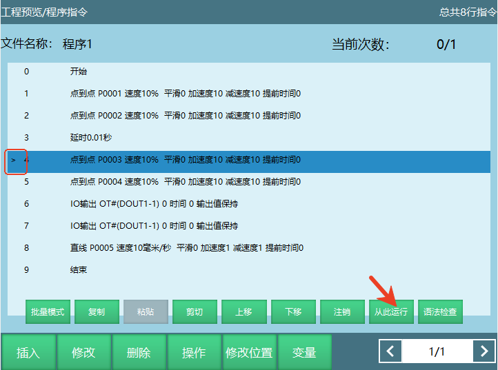
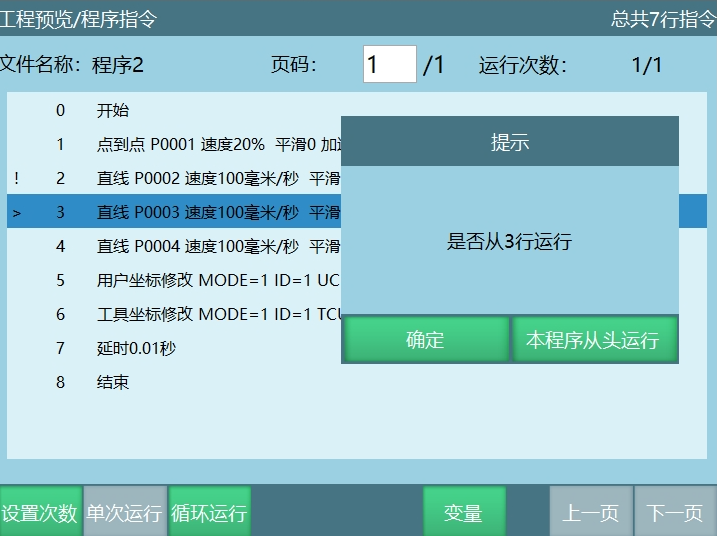
- Switch operation mode to run mode, click [Start]. Click [OK] in the prompt to run from the selected line. Click [Run From This Program From Beginning] to run from line 2.
Subroutine Set Current Line
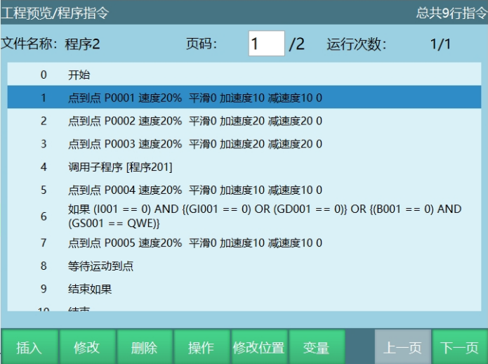
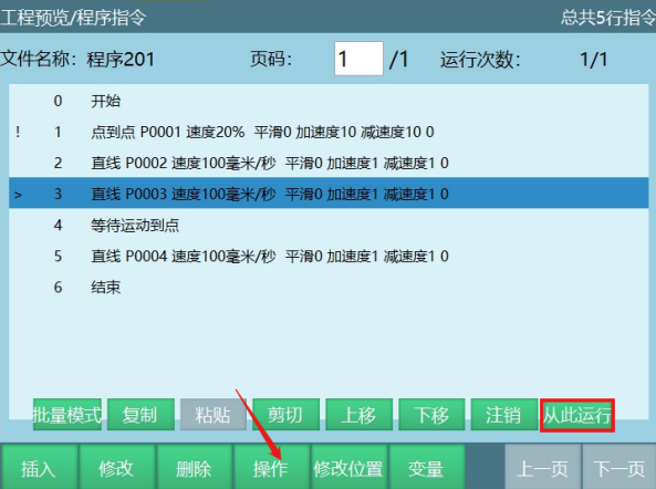
Call subroutine in main program. When running to the subroutine, switch operation mode to teach mode.
Select a line, click [Operations], click [Run From Here]. A > symbol appears on the selected line.
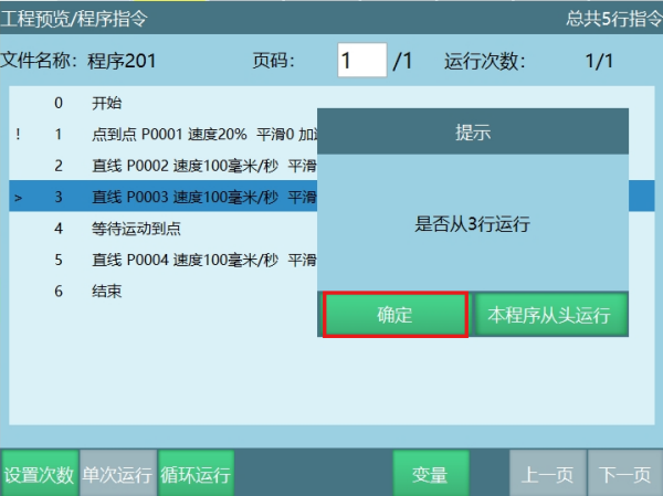
Switch to run mode, click [Start]. Click [OK] in the prompt to run from the selected line 3. After subroutine completes, return to main program and continue executing the next instruction.
Click [Run From This Program From Beginning] to run subroutine from the beginning without returning to main program.
Breakpoint Run
Breakpoint run: When running a program, if power is cut or other operations cause program interruption, when the program starts again, it continues from the interrupted point.
Run mode breakpoint run example:
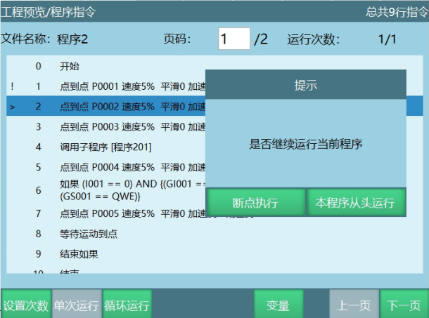
During run mode program execution (except the first instruction), switching to other modes causes interruption. The variable state and program position at interruption are saved as breakpoint. Breakpoint execution does not clear state.
When switching back to run mode and clicking [Start], a prompt appears. Select "Breakpoint Execute" to continue from breakpoint. Select "Re-run" to clear breakpoint and run from the first instruction.
Clear breakpoint operations:
Run mode: return to zero, reset, run other program, run to point, restart controller, modify robot parameters.
Run mode switch to teach mode: insert/delete/move/cut/copy-paste instructions.
Run mode switch to teach mode: modify numeric variables/position variables/program instruction parameters.
Controller error.
Example: During program running, switch mode, perform return to zero operation, then switch to run mode and find breakpoint is cleared, as shown below.
- Non-clear breakpoint operations
Run mode: IO emergency stop/servo alarm/output message instruction.
During program execution, power off to exit current job file, then re-run the exited job file.
During program execution, power off, switch to teach mode to jog robot, then re-run the exited job file.
Remote Mode Operation
Remote Mode Control Description
When the control system has teach pendant, Modbus device and IO control device simultaneously, control priority is: Teach pendant > Modbus device > IO device.
After switching to remote mode, control switches to touch screen. If no touch screen, control switches to IO control. At this time, teach pendant interface only displays Modbus module, IO module connection status, and IO program.
When both touch screen and I/O module are present, set IO module enable in the touch screen.
After job file programming in teach mode, rotate the knob in the upper right of the teach pendant to the right. Operation mode switches to remote mode.
How to start program in remote mode: IO start, Modbus start.
Remote mode program run steps:
Write program in teach mode;
Set parameters in Settings - Remote Program Settings interface;
Switch operation mode to remote mode;
Give signal to selected job file;
Job file runs.
Remote Mode IO Start Program
Remote Program Settings
Click [Settings] - [Remote Program] to enter the remote program settings interface.
Remote Parameters
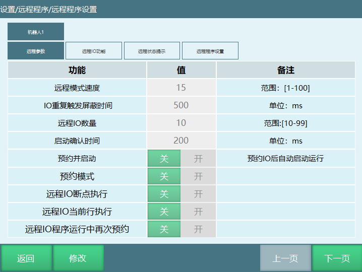
- Remote mode speed: Global speed when switching to remote mode, range [1,100]%.
Example: Set remote mode speed to 30% in remote parameters interface. After switching to remote mode, global speed is 30%.
- IO repeat trigger mask time: Mask time for repeat reservation of programs.
Example: Set repeat mask time to 500ms. After job file "Program 2" is first reserved for startup, if "Program 2" is reserved again, the signal is masked for 500ms. After 500ms, if signal is given again, "Program 2" status is reserved.
- Remote IO program count [10,99]: Number of programs that can run in remote mode.
Example: Set IO program count to 20 in remote parameters interface. The "Function" column in the remote IO function interface shows Remote IO Program 1 --- Remote IO Program 20. The remote status prompt interface shows Remote IO Program 1 Output --- Remote IO Program 20 Output. The remote program settings interface shows Program 1 --- Program 20.
Notes:
Remote mode interface only displays 10 queues. If selected program count exceeds 10, queue order displays the first 10 based on programs selected in remote program settings interface.
If more than 10 remote programs are set, only the first 10 are displayed in the remote program interface. However, programs not displayed can be started through remote IO.
Example: Set 12 programs in remote program settings interface. Only the first 10 programs are displayed in the remote interface. Programs 11 and 12 can be started normally through the set startup signal, just not displayed in the "Program Number" column of the remote interface.
Startup confirmation time [200,1000]ms: Program startup confirmation time. If set to 500ms, signal must be continuously triggered for 500ms.
Reserve and Start: Signal 0-1 (press button) for more than 0.6 seconds, then 1-0 (release button), program runs directly.
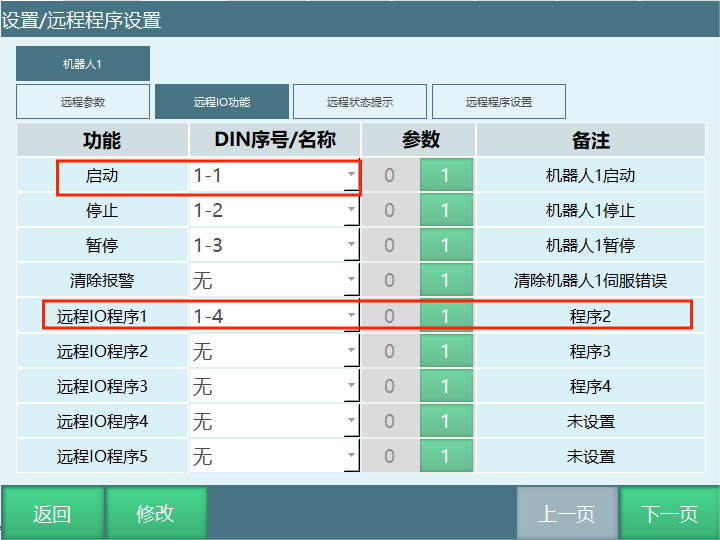
On: Enable Reserve and Start. As shown, in remote mode, after giving 1-4 signal, servo powers on and job file "Program 2" starts running.
Off: Disable Reserve and Start. In remote mode, after giving 1-1 startup signal, servo powers on. Then give 1-4 signal for job file "Program 2" to run.
- Reservation mode: Reserve programs in remote mode.
Reservation mode on: Trigger remote IO program 1 signal → robot runs; at this time if remote IO program 2 signal is triggered, remote IO program 2 is reserved. After remote IO program 1 completes, remote IO program 2 runs.
Reservation mode off: Trigger remote IO program 1 signal → robot runs; at this time if remote IO program 2 signal is triggered, it is invalid. After remote IO program 1 completes, give startup signal to remote IO program 2 for it to run.
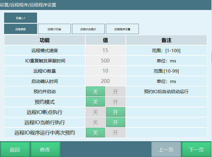
Remote IO breakpoint execution: Turn on switch to enable breakpoint execution in remote mode. Turn off to disable. Remote mode breakpoint execution requires this switch to be on.
Remote IO current line execution: Turn on switch to enable current line execution in remote mode. Turn off to disable. Remote mode current line execution requires this switch to be on.
Note: If both breakpoint and current line switches are off, when program is interrupted during execution, it will run from the first line when restarted.
- Remote IO program re-reservation during run: Turn on reservation switch to allow re-reservation during program run. Turn off to disable. Only programs in "Reserved" or "Not Reserved" state can be reserved.
Remote IO Function
| Function | Mode | Trigger/Output Method | Description | |
|---|---|---|---|---|
| Digital IO Input | Start | Remote Mode | Rising Edge | When parameter is 1, effective when signal changes 0→1 |
| Digital IO Input | Stop | Remote Mode | Continuously Effective | When parameter is 1, signal is continuously effective |
| Digital IO Input | Pause | Remote Mode | Continuously Effective | When parameter is 1, signal is continuously effective |
| Digital IO Input | Clear Alarm | Remote Mode | Rising Edge | When parameter is 1, effective when signal changes 0→1 |
| Digital IO Input | Clear Power-Off Retention Data | Remote Mode | Rising Edge | When parameter is 1, effective when signal changes 0→1 |
| Digital IO Input | I/O Program 1-10 | Remote Mode | Pulse (0.6s period) | When parameter is 1, effective when signal 0-1-0. Program reservation requires trigger for at least 0.6 seconds. |
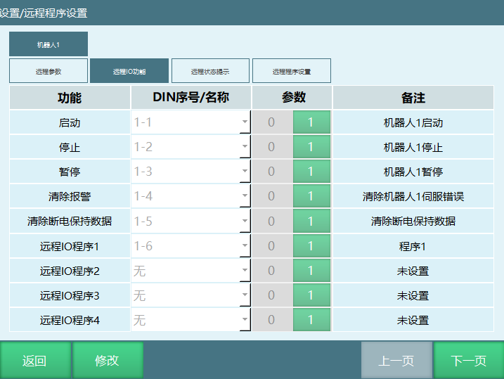
| Function Column | DIN Number Column | Parameter Column |
|---|---|---|
| Start: In remote mode, after giving 1-1 start signal, servo powers on, servo status switches to running. Stop: In remote mode, after giving 1-2 stop signal, job file stops running, program status changes from running to stopped, servo powers off. Pause: In remote mode, after giving 1-3 pause signal, job file pauses, program status changes from running to paused. Clear Alarm: In remote mode, clear errors (servo error, controller error). If error occurs during program execution, giving 1-4 signal clears the error. Clear Power-Off Retention Data: After triggering 1-5 signal, some data before breakpoint is cleared (breakpoint record, IO signal, current robot position, program status, variable values, etc.) Remote IO Program: Job file name running in remote mode. | Set IO port number for each function | When parameter is 1, selected IO port rising edge (signal from low 0 to high 1) is effective. When parameter is 0, selected IO port falling edge (signal from high 1 to low 0) is effective. |
Remote Status Prompt
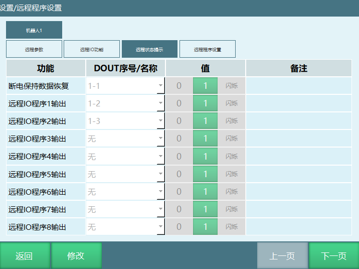
When program runs in remote mode, the set IO output port values change. Through port value changes, you can know the current program status.
Remote IO program output: Corresponds to remote IO program 1 in the remote IO function interface. When the program selected by remote IO program 1 starts running, the selected IO port outputs a prompt.
Power-Off Retention Data Recovery: After power off and power on again, after all data before power off is recovered, the corresponding port has an output prompt.
DOUT number: After selecting IO port, during program execution the corresponding port outputs a prompt.
Related values:
"0" Corresponding port is low level when program is running.
"1" Corresponding port is high level when program is running.
"Blink" Corresponding port blinks when program is running.
Notes: During remote mode program execution, IO output port only outputs prompts when program status is paused or running. When program status is stopped, IO output port does not output prompts.
Remote Program Settings
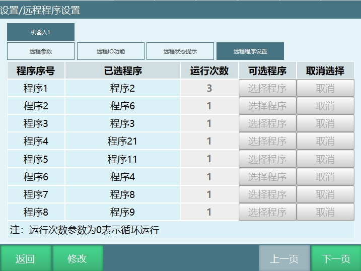
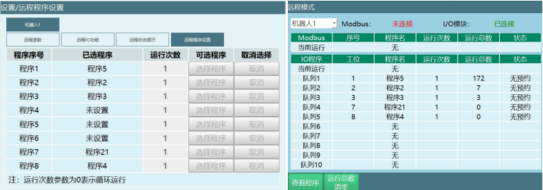
Program Number: The number of program numbers displayed in this interface is determined by the remote IO program count in the remote parameters interface. If IO program count is 15, this interface shows Program 1 --- Program 15.
Selected Program: Click "Select Program" in this interface to enter the program interface. Selected program is the target program.
Run Count: Number of times the target program runs. Enter 0 for loop execution.
Available Programs: Click "Select Program" to enter the program interface and select the target program.
Deselect: Deselect the target program. After deselecting, the selected program column shows "Not Set".
Remote Mode Interface Parameter Introduction
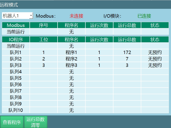
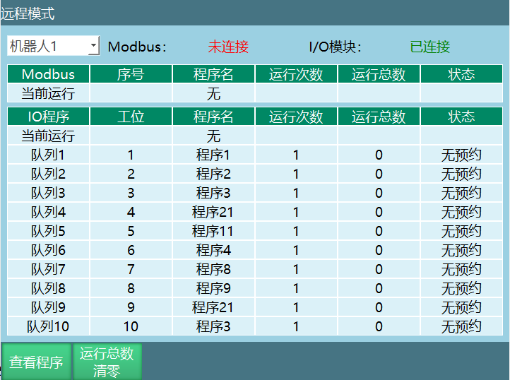
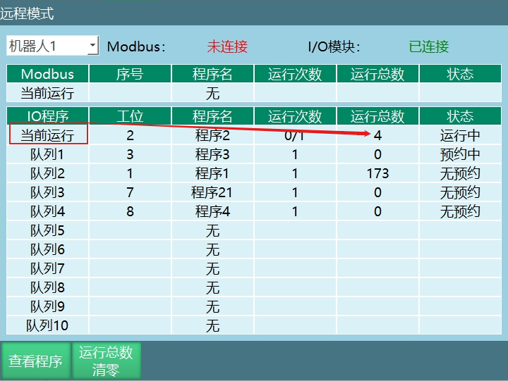
Queue: Remote mode interface only displays 10 queues. "Current Run" row shows the currently running program.
Station: Station display in this interface is based on the program number column order in the program settings interface, as shown below:
Program Name: Name of the selected job file.
Run Count: Number of times the job file runs. If run count is 3, program runs 3 times consecutively. After 3 runs, job file stops.
Total Runs: Total number of program runs, accumulates program run counts.
View Program: When program is running, click [View Program] to enter the program run interface and view detailed program execution.
Reset Total Runs: Clear the total runs of the currently running program without clearing the run count.
Remote Run Status Description
No Reservation: After entering remote mode, no programs have been reserved or reservations have been cancelled. Displays "No Reservation".
Reserved: During program execution, triggering the corresponding program's IO port successfully reserves the program. To cancel, trigger the program's corresponding IO port again.
Running: Program is currently running.
Reserved: After program completes, displays "Reserved".
Paused: During program execution, pause signal was triggered. Program status is paused.
Program Error: During program execution, an error occurred. The running program status is "Program Error".
Notes: For program reservation run, the reservation mode must be enabled in the remote parameters interface.
Assume the programs to run in queue 1, 2, 3 are Program 1, Program 2, Program 3.
Trigger remote IO program 1 signal → trigger start signal → robot runs. At this time, Program 1 status is "Running".
Trigger remote IO program 2 signal - Program 2 status is "Reserved". After Program 1 completes, Program 2 runs.
Trigger remote IO program 3 signal - Program 3 status is "Reserved". After Program 2 completes, Program 3 runs.
Remote IO Breakpoint and Current Line Execution
Remote mode IO breakpoint execution and current line execution require switches to be turned on. Otherwise, when program execution is interrupted due to mode switching or other operations, breakpoint and current line will not take effect when restarting.
| IO Breakpoint Off | Remote IO Current Line Off | Servo Alarm: Main program: Execute from first line Subroutine: Start from first line of main program IO Emergency Stop: Main program: Execute from first line Subroutine: Start from first line of main program Mode Switch: Main program: Execute from first line Subroutine: Start from first line of main program |
| IO Breakpoint On | Remote IO Current Line On | Servo Alarm: Main program: Breakpoint execution Subroutine: Breakpoint execution IO Emergency Stop: Main program: Breakpoint execution Subroutine: Breakpoint execution Mode Switch: Main program: Breakpoint execution Subroutine: Breakpoint execution |
Remote Mode Modbus Start Program
Modbus Start Program
Job file programming.
Click Settings - External Communication - Modbus Program, enter program selection interface and select the target program.
4X type address code 6 write 2, switch operation mode to remote mode (need to remove teach pendant).
4X type address code 29 write 1, servo ready.
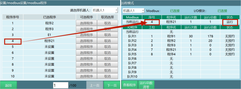
Address code selects job file. 4X type address code 45 enter value. The entered value corresponds to the selected program number.
Example: To run job file "Program 21" with program number 4, write 4 to 4X type address code 45.
- 4X type address code 19 write 1, run job file "Program 21". At this time, the currently selected program status is "Running".
Description: If you need to set run count, run speed, and other parameters, refer to the "Modbus Address Code List".
Modbus Breakpoint and Current Line Run
When Modbus remote start program runs, if program execution is interrupted due to mode switching or other operations, when starting the program again, it can perform breakpoint execution and current line execution.
4X type address code 19 write 0, stop running;
4X type address code 19 write 1, start running;
4X type address code 19 write 2, pause running;
4X type address code 19 write 3, breakpoint execution;
4X type address code 19 write 4, current line execution;
4X type address code 169 write 4, set current robot run line number.
Modbus and IO Priority
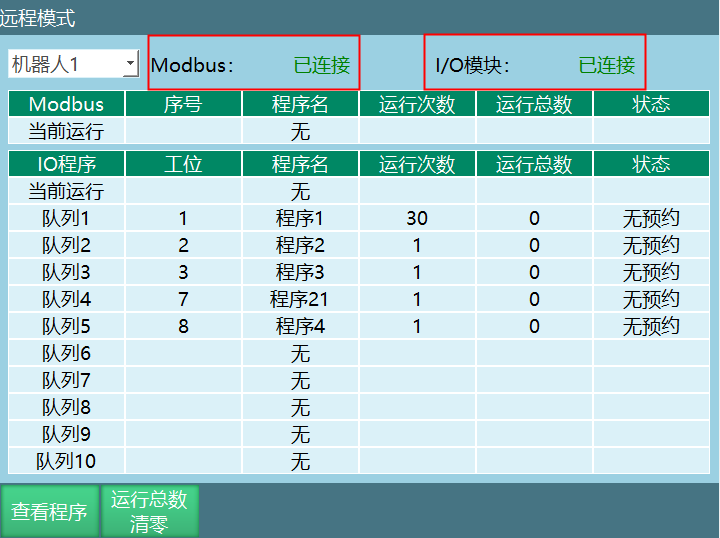
When both Modbus and IO are connected, there is a priority for remote program startup.
How to modify priority?
Click Settings - System Configuration - Maintenance Mode to enter other interface, turn on shared switch, and select which has higher priority.
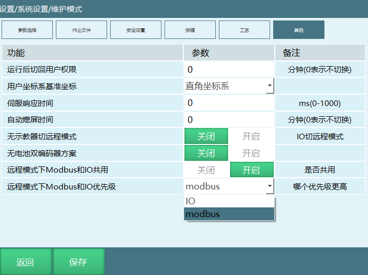
| Not Shared - coexistIOControl: false | Modbus has higher priority. When Modbus is connected, IO cannot control the robot. |
| Shared - coexistIOControl: true | Both Modbus and IO can control the robot When shared, as long as the higher priority side is not connected, the other side's function is not available. - modbusPriorityHigh: true Modbus and IO shared with Modbus higher priority. Starting program through IO uses the program selected on the Modbus side |
| Shared - coexistIOControl: true | Both Modbus and IO can control the robot When shared, as long as the higher priority side is not connected, the other side's function is not available. - modbusPriorityHigh: false Modbus and IO shared with IO higher priority. Starting program through Modbus uses the program set on the IO side. If IO breakpoint and current line are not enabled, Modbus breakpoint and current line settings will not take effect. Program still runs from the first line |
Remote Mode Speed
Remote mode global speed can be set in the remote parameters interface.
| Remote Mode | Joint: Maximum axis speed = Rated forward speed * Instruction speed * Global speed Cartesian: Maximum linear speed = Instruction speed * Global speed |
Q&A for Retrieval
Q: What safety checks are needed before teach pendant power-on?
A: Before teach pendant power-on, check that the servo, controller, and teach pendant connection cables are properly connected, and confirm the emergency stop button is normal.
Q: How to start servo power?
A: Rotate the main power switch on the cabinet panel to ON position, then press the green servo start button on the cabinet panel.
Q: How to power on through the DEADMAN button?
A: Gently press the [DEADMAN] button (button on the back of the teach pendant). Robot powers on, teach pendant displays "Servo Running", indicating servo power is successfully connected.
Q: How to import robot configuration file?
A: Click [Settings] - [Robot Parameters] - [Robot Type] to set robot type, then click [Settings] - [System Configuration] - [Import Controller Configuration] to select configuration file. After system restart, robot parameter configuration is imported successfully.
Q: What needs to be checked after importing configuration file?
A: After importing configuration file, check servo order, model direction, and zero position to ensure servo slave order is correct when jogging, actual direction matches model direction, and zero position is accurate.
Q: How to create a new project program?
A: Click [Project] to enter the project interface, click New, select program type, enter program name and click [OK]. Program name must be a string of 2 or more characters starting with a letter/Chinese character, cannot exceed 30 characters.
Q: How to encrypt a program?
A: Select the program, click Operations, click Encrypt. Encrypted programs allow viewing but not operations (modify, delete, copy, etc.), with a lock icon on the far right.
Q: What is the mirror program function?
A: The mirror program function mirrors points in the program by a specified plane. Only supports 6-axis serial robots, useful for programming symmetrical workpieces.
Q: How to batch modify instruction parameters?
A: Click [Operations] - [Batch Mode], select multiple instructions to modify, select [Modify], turn on the enable switch for parameters to modify, enter parameter values and click [OK].
Q: What is single step run?
A: Single step run means after pressing the single step button, the robot executes the selected instruction line, stops after execution, and the selected line automatically jumps to the next line. Programs can be run instruction by instruction.
Q: What is trial run?
A: Trial run function uses the [Start] key as the trial run button in teach mode. Power on, hold [Start] to keep running, release to stop. Trial run supports all instructions but does not support reverse execution or background programs.
Q: How to calculate single step joint speed in teach mode?
A: Single step joint speed = Global speed × Instruction speed × Joint rated forward speed. Maximum speed limit is Joint rated forward speed × 30%.
Q: How to calculate single step Cartesian speed in teach mode?
A: Single step Cartesian speed = Global speed × Instruction speed. Maximum speed limit is 300mm/s.
Q: What is global speed segmentation?
A: Global speed segmentation allows users to set multiple speed segments. Each segment can be individually named and set. Speed segments increase sequentially. When the last segment speed is below 100, new segments can be added.
Q: How to set the main program?
A: Select the program, click [Operations] - [Set as Main Program]. The program set as main program will have a "*" before its name for easy identification when running.
Q: How to perform cross-job file instruction operations?
A: In batch mode, select multiple instructions to copy and copy them. Then click [Project] to open the target job file, select the paste position and click [Paste] to paste instructions to another job file.
Version History
| Version | Date | Changes | Author |
|---|---|---|---|
| 1.0.0 | 2026-06-30 | Initial version | qiuzegai |