Tool Hand Calibration Manual
Tool Hand Calibration
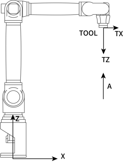
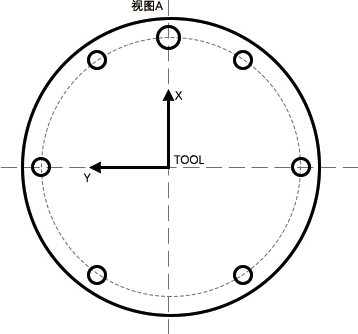
Flange Center: The default tool coordinate system origin. The direction from the flange center to the flange positioning hole is the +X direction, perpendicular to the flange outward is the +Z direction, and the Y direction is determined by the right-hand rule. New tool coordinate systems are all obtained by transforming the default tool coordinate system.
Why Build a Tool Coordinate System?
- Every robot has a default tool coordinate system Tool 0: position at the flange center. However, during actual robot motion, tools such as suction cups (Figure 1) or welding guns (Figure 2) are often installed at the flange center. If the manipulator's motion center remains at the flange center, it causes great inconvenience. Therefore, it is necessary to teach the required tool coordinate system based on actual conditions.
For example: During welding, a welding gun needs to be installed at the robot end (flange center). Users typically define the TCP point at the wire tip. The position recorded in the program is the wire tip position, and the recorded orientation is the welding gun's rotation around the wire tip.
- For industrial robots, tools need to be installed on the end flange for operations. To determine the tool's pose, a Tool Coordinate System (TCS) is bound to the installed workpiece. The origin of TCS is the TCP (Tool Center Point).
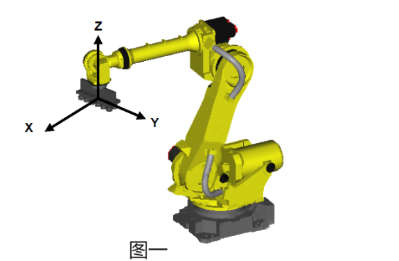
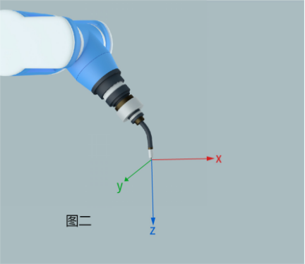
Thought: We know that the tool coordinate system is a research object in motion, but what role does it play in actual debugging? Think about how the gripper's orientation and position in Figures 1 and 2 are adjusted?
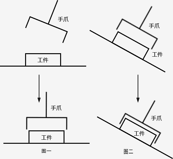
From the thought, two inferences can be drawn:
Inference 1: If the gripper in Figure 1 has a rotation point, the gripper can directly rotate around this rotation point.
Inference 2: If there is a gripper's forward direction in Figure 2, it can be moved directly.
Conclusion: The functions of building a tool coordinate system:
Establish the tool's TCP point (Tool Center Point) for convenient tool state adjustment.
Determine the tool feed direction for convenient tool position adjustment.
Tool Coordinate System Characteristics:
The new tool coordinate system is obtained by transforming relative to the default tool coordinate system. The position and orientation of the new tool coordinate system always maintain an absolute position and orientation relationship with the flange, but it constantly changes in space.
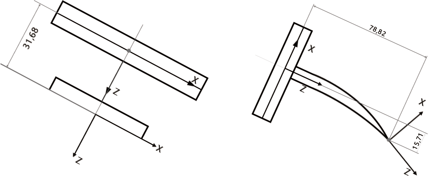
When to use tool hand: When rotational movements around X, Y, Z axes are needed, tool hand calibration is required.
When not to use tool hand: When the robot itself only performs Z-axis orientation rotation, and the tool tip is located on the extension line of the robot's 6th axis flange center; in this case, tool hand parameters do not need to be set.
Applicable Scenarios
When the robot's X, Y, Z axes need to rotate around A, B, C orientation axes during operation, tool hand calibration is required, such as welding processes, grinding processes, spraying processes, etc.
Choosing Calibration Method for Different Scenarios
- Robot has performed laser calibration + uses welding gun.
Recommendation: Use 6-point calibration for the tool hand. After calibration, verify the robot calibration results.
- Robot has not performed laser calibration + uses welding gun.
Recommendation: Use 12-point calibration for the tool hand. After calibration, verify the robot calibration results.
- Calibrating palletizing gripper.
Recommendation: Prefer directly filling in tool dimensions. For unknown dimensions, use 6-point calibration.
How to directly fill in gripper dimensions?
Prepare the gripper's length, width, and height parameters.
Fill the gripper tip's X-axis offset into "X-axis direction offset".
Note: If the tip is in the positive direction of the Cartesian X-axis, fill in a positive value.
- Fill the gripper tip's Y-axis offset into "Y-axis direction offset".
Note: If the tip is in the positive direction of the Cartesian Y-axis, fill in a negative value.
- Fill the gripper tip's Z-axis offset into "Z-axis direction offset".
Note: If the tip is in the positive direction of the Cartesian Z-axis, fill in a negative value.
- After saving, verify the tool hand rotation A, B, C precision.
How to perform 6-point calibration?
Prepare a pointed object that can be gripped. Place the object as close to the gripper center as possible, then find a calibration cone with a tip and follow the 6-point calibration steps for tool hand calibration.
- Robot zero point lost, zero point position calibrated by alignment holes has deviation.
Recommendation: Prepare a calibration tool. The tool tip should be as close as possible to the extension line of the 6th axis flange center, with a small tool size.
Use 20-point calibration to calibrate the zero point. After 20-point calibration, switch to the actual tool hand for 6-point calibration.
- After 6-point calibration, A, B axis rotation error is large and cannot meet usage requirements.
Recommendation: Switch to 7-point calibration.
Tool Hand Parameters
Click Settings - Tool Hand Calibration to enter the tool hand calibration interface, as shown:
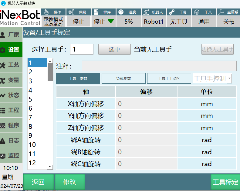
Tool hand parameters:
| Axis | Offset | Unit |
|---|---|---|
| X-axis | Offset length of tool end relative to flange center along Cartesian coordinate system X-axis direction | Millimeters (mm) |
| Y-axis | Offset length of tool end relative to flange center along Cartesian coordinate system Y-axis direction | Millimeters (mm) |
| Z-axis | Offset length of tool end relative to flange center along Cartesian coordinate system Z-axis direction | Millimeters (mm) |
| A-axis | Rotation angle of tool end relative to flange center around Cartesian coordinate system X-axis direction | Degrees/Radians (°/rad) |
| B-axis | Rotation angle of tool end relative to flange center around Cartesian coordinate system Y-axis direction | Degrees/Radians (°/rad) |
| C-axis | Rotation angle of tool end relative to flange center around Cartesian coordinate system Z-axis direction | Degrees/Radians (°/rad) |
With installed tool detailed parameters:
Select tool hand number, click [Modify], then fill in the installed tool hand parameters;
Click [OK];
Click [Select]. At this time, the tool hand number displayed in the toolbar above the status bar is the selected tool number;
In this interface, users can directly fill in tool end offset related parameters without performing tool hand calibration. If changing the tool hand, please refill;
Without installed tool detailed parameters (Tool Hand Calibration):
Tool Hand Calibration Methods
| Calibration Method | Function |
|---|---|
| 6-point calibration | Calibrate tool hand size + orientation. Calibration result has good C-axis rotation precision |
| 7-point calibration | Calibrate tool hand size + orientation. Calibration result has good A, B-axis rotation precision |
| 12-point calibration | Calibrate zero point for axes 2, 3, 4, 5 + tool hand size |
| 15-point calibration | Calibrate zero point for axes 2, 3, 4, 5 + calibrate tool hand size + orientation |
| 20-point calibration | Calibrate zero point for axes 2, 3, 4, 5 + tool hand size |
6-Point Calibration
Click Settings - Enter tool hand calibration interface, click [Tool Hand Calibration].
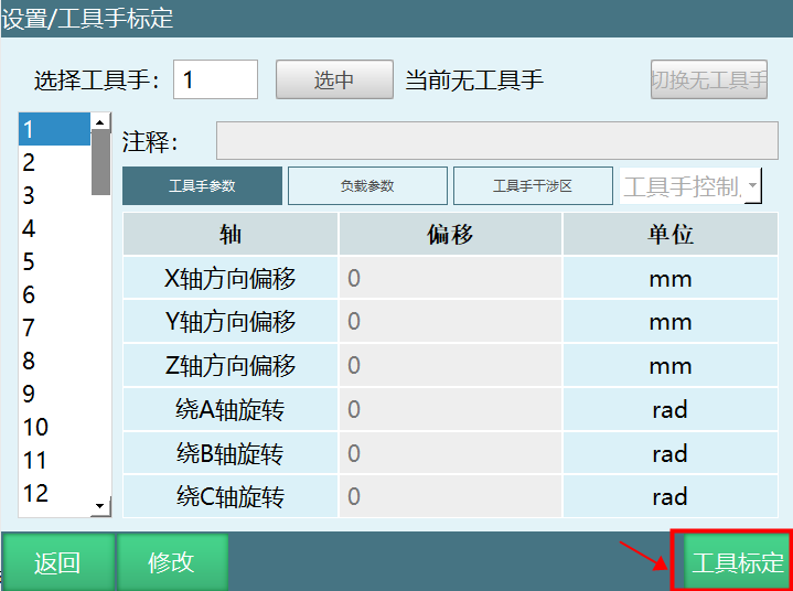
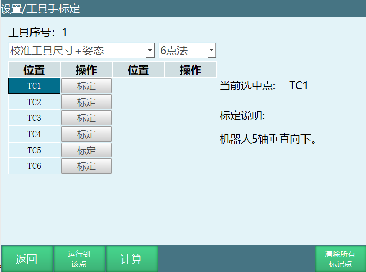
Calibration Steps:
TC1 Calibration: Robot 5th axis vertically downward
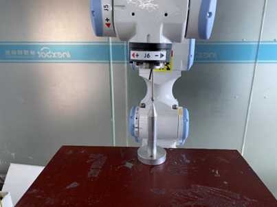
TC2 Calibration: Robot rotates C-axis 180° from the first point
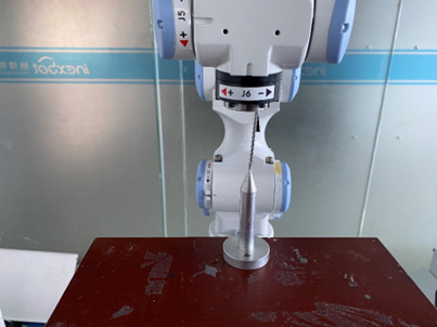
TC3 Calibration: Robot B-axis angle at 35° from the first point
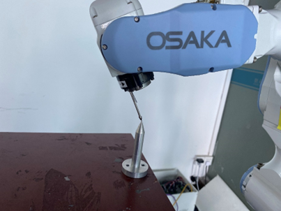
TC4 Calibration: Robot returns to zero point, then tool hand tip is vertical
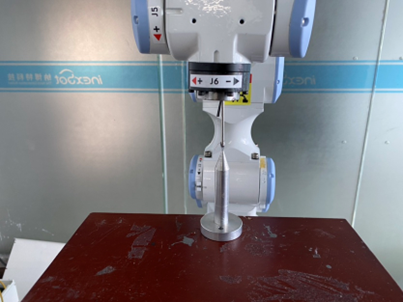
TC5 Calibration: Robot moves X- from the fourth point
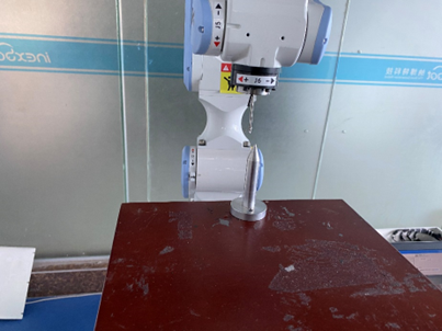
TC6 Calibration: Robot moves Y+ from the fifth point
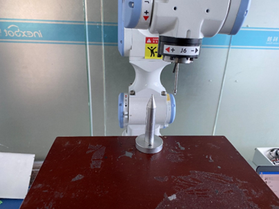
[Calculate]: After six points are calibrated, click "Calculate" to get the result. If the calculation result is greater than 1, recalibration is needed.
[Run to Point]: Select any marked point, click "Run to Point" and the robot will move to the selected position.
[Clear All Marked Points]: Clear all 6 marked points.
[Return]: Return to the "Tool Hand Calibration" interface.
If dissatisfied with a point during calibration, click the [Cancel Calibration] button corresponding to that row. After canceling, recalibrate that point.
How to verify calibration precision:
In teach mode, align the tool hand calibration tip with the calibration cone. With the tips aligned, select the calibrated tool hand parameters, switch the jogging coordinate system to Cartesian, and jog the A, B, C axes to see if the tips remain aligned and how many mm deviation there is.
7-Point Calibration
Click Settings - Enter tool hand calibration interface, click [Tool Hand Calibration].
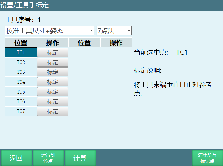
Calibration Steps:
TC1: Tool hand tip vertically aligned with reference point;
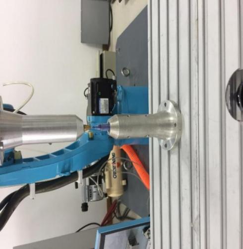
TC2 Calibration: Switch the robot to a different posture, end facing the reference point;
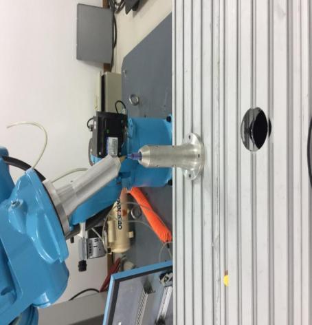
TC3 Calibration: Switch the robot to a different posture, end facing the reference point;
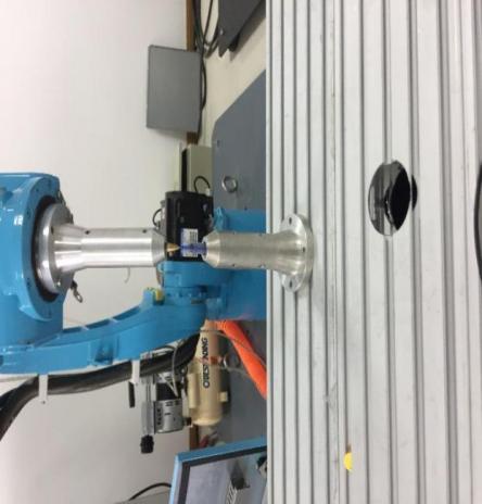
TC4 Calibration: Switch the robot to a different posture, end facing the reference point;
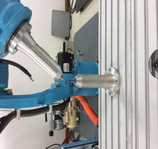
TC5 Calibration: Tool end vertically facing the reference point (same as TC1);
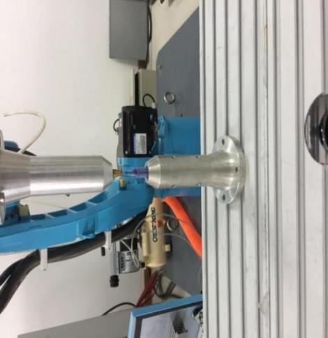
TC6 Calibration: From TC5, move any distance in the negative X-axis direction of the Cartesian coordinate system;
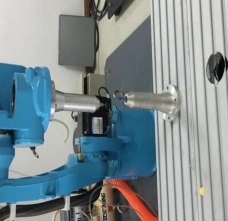
TC7 Calibration: From TC6, move any distance in the positive Y-axis direction of the Cartesian coordinate system;
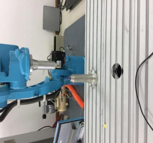
[Calculate]: After seven points are calibrated, click "Calculate" to get the result. If the calculation result is greater than 1, recalibration is needed.
[Run to Point]: Select any marked point, click "Run to Point" and the robot will move to the selected position.
[Clear All Marked Points]: Clear all 7 marked points.
[Return]: Return to the "Tool Hand Calibration" interface.
If dissatisfied with a point during calibration, click the [Cancel Calibration] button corresponding to that row. After canceling, recalibrate that point.
| Warning |
|---|
 |
| Please ensure the flange is parallel to the horizontal plane before data collection! |
12-Point Calibration
The 12-point calibration result only contains the tool hand's XYZ axis direction offsets, without ABC rotation values.
Click Settings - Enter tool hand calibration interface, click [Tool Hand Calibration].
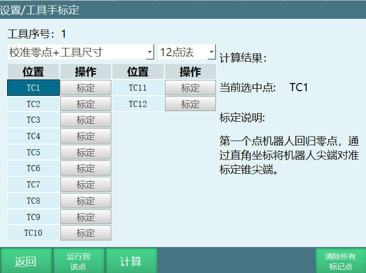
Calibration Steps:
Find a reference point (calibration cone tip as reference point) and ensure this reference point is fixed.
TC1: First point, robot returns to zero point. Through Cartesian coordinates, align the robot tip with the calibration cone tip.
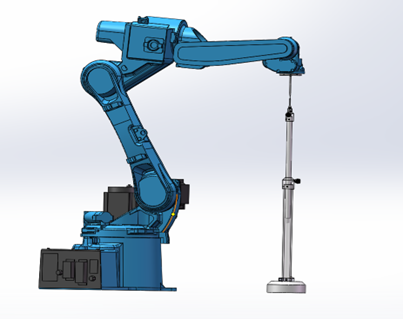
TC2: Second point, from the first point, rotate C 180 degrees through Cartesian coordinate system; align tip to calibrate second point.
TC3: Third point, robot returns to zero point. Through Cartesian coordinates, align the robot tip with the calibration cone tip; calibrate the third point (same as the first point).
TC4: Fourth point, from the third point, do B- through Cartesian coordinate system, angle between 30°-60°, align tip to calibrate the fourth point.
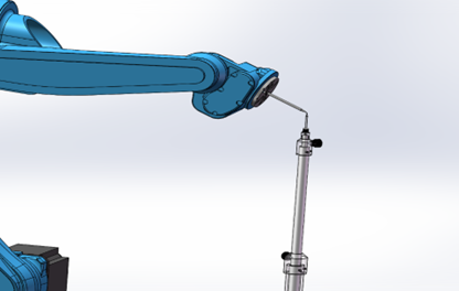
TC5: Fifth point, from the fourth point, do B+ through Cartesian coordinate system, J5>-90°, align the robot tip with the calibration cone tip, calibrate the fifth point.
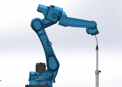
TC6: Select the first point and move the robot to the first point. From the first point, do B+ through Cartesian coordinate system, J5>-90°, align tip to calibrate the sixth point.
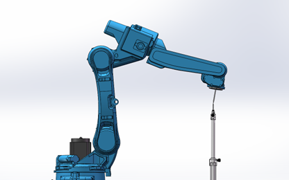
TC7: From the first point, do B- through Cartesian coordinate system, J5>-90°, align tip to calibrate the seventh point.
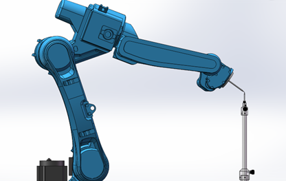
TC8: From the seventh point, do A+ through Cartesian coordinate system, rotate 90°, J5>-90°, align tip to calibrate the eighth point.
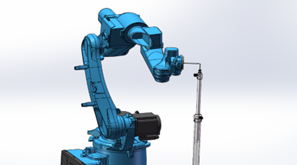
TC9: From the seventh point, do A- through Cartesian coordinate system, rotate 90°, J5>-90°, align tip to calibrate the ninth point.
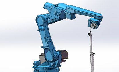
TC10: Return to the first point. Through joint coordinate system, jog the fifth axis upward, J5<-90°, align the tip, calibrate the tenth point.
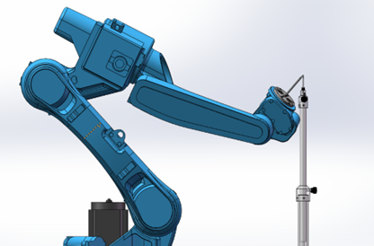
TC11: From the tenth point, do A+ through Cartesian coordinate system, rotate 90°, J5<-90°, align tip to calibrate the eleventh point.
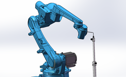
TC12: From the tenth point, do A- through Cartesian coordinate system, rotate 90°, J5<-90°, align tip to calibrate the twelfth point.
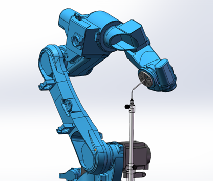
[Calculate]: After calibration is complete, click Calculate to get the calibration result. If the calculated value is large, recalibration is needed.
[Cancel Calibration]: If dissatisfied with a point during calibration, click the [Cancel Calibration] button corresponding to that row. After canceling, recalibrate that point.
[Run to Calculation Result Position]: Robot moves to the zero point position after correction.
[Run to Point]: Select any marked point, click "Run to Point" and the robot will move to the selected position.
[Mark Result Position as Zero Point]: Set the calibration compensation position as the current robot's zero point position.
[Clear All Calibration Points]: Clear all 12 marked points.
[Return] Return to "Tool Hand Calibration" interface.
15-Point Calibration
Click Settings - Enter tool hand calibration interface, click [Tool Hand Calibration].
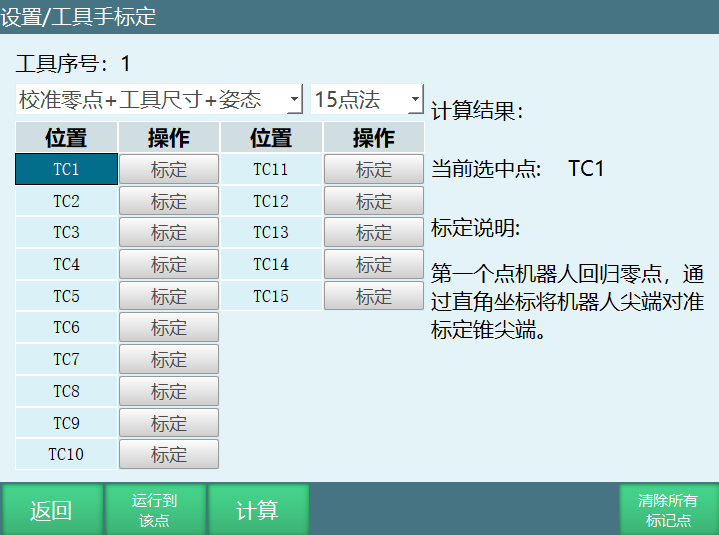
Calibration Steps:
Find a reference point (calibration cone tip as reference point) and ensure this reference point is fixed.
TC1: First point, robot returns to zero point. Through Cartesian coordinates, align the robot tip with the calibration cone tip.
TC2: From the first point, rotate C 180 degrees through Cartesian coordinate system, align tip to calibrate second point.
TC3: Robot returns to zero point. Through Cartesian coordinates, align the robot tip with the calibration cone tip, calibrate the third point.
TC4: From the third point, do B- through Cartesian coordinate system, angle between 30°-60°, align tip to calibrate the fourth point.
TC5: From the fourth point, do B+ through Cartesian coordinate system, J5>-90°, align the robot tip with the calibration cone tip, calibrate the fifth point.
TC6: Select the first point and move the robot to the first point. From the first point, do B+ through Cartesian coordinate system, J5>-90°, align tip to calibrate the sixth point.
TC7: From the first point, do B- through Cartesian coordinate system, J5>-90°, align tip to calibrate the seventh point.
TC8: From the seventh point, do A+ through Cartesian coordinate system, rotate 90°, J5>-90°, align tip to calibrate the eighth point.
TC9: From the seventh point, do A- through Cartesian coordinate system, rotate 90°, J5>-90°, align tip to calibrate the ninth point.
TC10: Robot returns to the first point. Through joint coordinate system, jog the fifth axis upward, J5<-90°, align the tip to calibrate the tenth point.
TC11: From the tenth point, do A+ through Cartesian coordinate system, rotate 90°, J5<-90°, align tip to calibrate the eleventh point.
TC12: From the tenth point, do A- through Cartesian coordinate system, rotate 90°, J5<-90°, align tip to calibrate the twelfth point.
TC13: Robot returns to zero position. Adjust robot posture so that the robot end tool tip points vertically downward. Align the calibration tip with the calibration cone to calibrate the thirteenth point.
TC14: From the thirteenth point, do X- through Cartesian coordinate system. Robot moves a certain distance, directly click to calibrate the fourteenth point.
TC15: From the fourteenth point, do Y+ through Cartesian coordinate system. Robot moves a certain distance, directly click to calibrate the fifteenth point.
[Calculate]: After calibration is complete, click Calculate to get the calibration result. If the calculated value is large, recalibration is needed.
[Cancel Calibration]: If dissatisfied with a point during calibration, click the [Cancel Calibration] button corresponding to that row. After canceling, recalibrate that point.
[Run to Calculation Result Position]: Robot moves to the zero point position after correction.
[Run to Point]: Select any marked point, click "Run to Point" and the robot will move to the selected position.
[Mark Result Position as Zero Point]: Set the calibration compensation position as the current robot's zero point position.
[Clear All Calibration Points]: Clear all 15 marked points.
[Return] Return to "Tool Hand Calibration" interface.
20-Point Calibration
Click Settings - Enter tool hand calibration interface, click [Tool Hand Calibration].
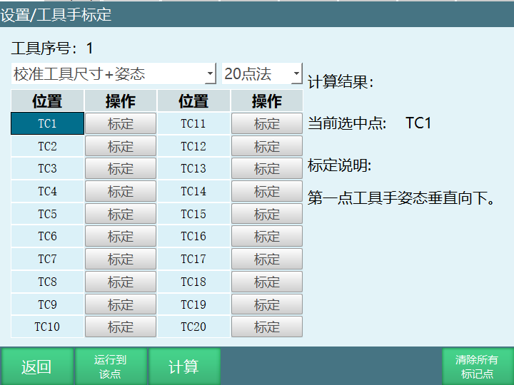
Calibration Steps:
TC1: Robot tool hand end vertically at reference point;
TC2: From the first point, do A+;
TC3: From the first point, do A+ 40 degrees;
TC4: From the first point, do A+ 60 degrees;
TC5: From the first point, do A- 20 degrees;
TC6: From the first point, do A- 40 degrees;
TC7: From the first point, do A- 60 degrees;
TC8: From the first point, do B+ 20 degrees;
TC9: From the first point, do B+ 30 degrees;
TC10: From the first point, do B+ 40 degrees;
TC11: From the first point, do B- 20 degrees;
TC12: From the first point, do B- 30 degrees;
TC13: From the first point, do B- 40 degrees;
TC14: From the first point, do C+ 30 degrees;
TC15: From the first point, do C+ 50 degrees;
TC16: From the first point, do C+ 70 degrees;
TC17: From the first point, do C+ 90 degrees;
TC18: From the first point, do C- 30 degrees;
TC19: From the first point, do C- 60 degrees;
TC20: Twentieth point, from the first point, do C- 90 degrees.
[Calculate]: After calibration is complete, click Calculate to get the calibration result. If the calculated value is large, recalibration is needed.
[Cancel Calibration]: If dissatisfied with a point during calibration, click the [Cancel Calibration] button corresponding to that row. After canceling, recalibrate that point.
[Run to Calculation Result Position]: Robot moves to the zero point position after correction.
[Run to Point]: Select any marked point, click "Run to Point" and the robot will move to the selected position.
[Mark Result Position as Zero Point]: Set the calibration compensation position as the current robot's zero point position.
[Clear All Calibration Points]: Clear all 15 marked points.
[Return] Return to "Tool Hand Calibration" interface.
| Note |
|---|
 |
| Please ensure the flange is parallel to the horizontal plane before data collection! Please keep the reference point fixed during calibration, otherwise calibration error will increase. |
How to Verify Calibration Precision
In teach mode, align the tool hand calibration tip with the calibration cone. With the two tips aligned, select the calibrated tool hand number, then jog the A, B, C axes in the Cartesian coordinate system to see if the tips remain aligned and how many mm deviation there is.
QA
Q: What is a tool coordinate system?
A: A tool coordinate system is the coordinate system of the robot's end tool. The origin is the TCP (Tool Center Point), used to determine the tool's pose.
Q: Why build a tool coordinate system?
A: 1. Establish the tool's TCP point for convenient tool state adjustment; 2. Determine the tool feed direction for convenient tool position adjustment.
Q: When is tool hand calibration needed?
A: When rotational movements around X, Y, Z axes are needed, tool hand calibration is required, such as welding processes, grinding processes, spraying processes, etc.
Q: When is tool hand not needed?
A: When the robot itself only performs Z-axis orientation rotation, and the tool tip is located on the extension line of the robot's 6th axis flange center; in this case, tool hand parameters do not need to be set.
Q: How to choose the tool hand calibration method?
A: 1. Laser calibration done + welding gun: Use 6-point calibration; 2. No laser calibration + welding gun: Use 12-point calibration; 3. Palletizing gripper: Prefer directly filling tool dimensions; 4. Zero point lost: Use 20-point calibration; 5. After 6-point calibration, A, B axis rotation error is large: Use 7-point calibration.
Q: How to directly fill in gripper dimensions?