Variable Manual
Variable Types
| Variable Type | Global Variable | Local Variable |
|---|---|---|
| Integer | GINT | INT |
| Float | GDOUBLE | DOUBLE |
| Boolean | GBOOL | BOOL |
| String | GSTRING | STRING |
Position Variables
| Variable Type | Description |
|---|---|
| P | Local position variable that records robot position data |
| GP | Global position variable that records robot position data |
| E | When the robot is connected to external axes, a local position variable that records external axis position data; when dual-robot mode is set, records position data of two robots. Dual-robot mode: "Both robots are six-axis serial multi-joint robots" |
| GE | When the robot is connected to external axes, a global position variable that records external axis position data; when dual-robot mode is set, records position data of two robots |
Note: Newly created or modified local position data is only saved in the current job file. Global position data is saved permanently. Different job files can call the same global position variable. When one file modifies a global position, the same global variable called in other job files will also be modified.
Reference Variables
Position Variable Reference Variables
Usage: When the local or global integer variable inside [] is assigned a value, the local or global position is the position represented by that value.
| Format | Example |
|---|---|
| P[INT/GINT] | P[I001], when I001=10, P[I001] is equivalent to P0010 P[GI001], when GI001=20, P[GI001] is equivalent to P0020 |
| GP[INT/GINT] | GP[I002], when I002=5, GP[I002] is equivalent to GP0005 GP[GI002], when GI002=10, GP[GI002] is equivalent to GP0010 |
| E[INT/GINT] | E[I003], when I003=8, E[I003] is equivalent to E0008 E[GI003], when GI003=12, E[GI003] is equivalent to E0012 |
| GE[INT/GINT] | GE[I004], when I004=15, GE[I004] is equivalent to GE0015 GE[GI004], when GI004=25, GE[GI004] is equivalent to GE0025 |
Numeric Variable Reference Variables
Usage: When the local or global integer variable inside [] is assigned a value, the local or global variable is the variable represented by that value.
| Format | Example |
|---|---|
| I[INT/GINT] | I[I002], when I002=12, I[I002] is equivalent to I012 I[GI002], when GI002=22, I[GI002] is equivalent to I022 |
| GI[INT/GINT] | GI[I003], when I003=3, GI[I003] is equivalent to GI003 GI[GI003], when GI003=5, GI[GI003] is equivalent to GI005 |
| D[INT/GINT] | D[I004], when I004=5, D[I004] is equivalent to D005 D[GI004], when GI004=7, D[GI004] is equivalent to D007 |
| GD[INT/GINT] | GD[I005], when I005=8, GD[I005] is equivalent to GD008 GD[GI005], when GI005=12, GD[GI005] is equivalent to GD012 |
| B[INT/GINT] | B[I006], when I006=11, B[I006] is equivalent to B011 B[GI006], when GI006=9, B[GI006] is equivalent to B009 |
| GB[INT/GINT] | GB[I007], when I007=14, GB[I007] is equivalent to GB014 GB[GI007], when GI007=15, GB[GI007] is equivalent to GB015 |
| S[INT/GINT] | S[I008], when I008=23, S[I008] is equivalent to S023 S[GI008], when GI008=17, S[GI008] is equivalent to S017 |
| GS[INT/GINT] | GS[I009], when I009=45, GS[I009] is equivalent to GS045 GS[GI009], when GI009=21, GS[GI009] is equivalent to GS021 |
IO Port Reference Variables
| Format | Example |
|---|---|
| AIN | Directly select the port based on the currently connected IO board |
| DIN | Directly select the port based on the currently connected IO board |
| DOUT | Directly select the port based on the currently connected IO board |
| AIN[INT/GINT] | AIN[I001], when I001=1, AIN[I001] is equivalent to AIN1-1 port AIN[GI001], when GI001=2, AIN[GI001] is equivalent to AIN1-2 port |
| DIN[INT/GINT] | DIN[I010], when I010=5, DIN[I010] is equivalent to DIN1-5 port DIN[GI010], when GI010=6, DIN[GI010] is equivalent to DIN1-6 port |
| DOUT[INT/GINT] | DOUT[I015], when I015=10, DOUT[I015] is equivalent to DOUT1-10 port DOUT[GI016], when GI016=11, DOUT[GI016] is equivalent to DOUT1-11 port |
Note: When using IO port reference variables, the defined variable value cannot exceed the number of ports on the currently connected IO board.
Numeric Variables
Global Numeric Variables
Numeric variables are divided into global numeric variables and local numeric variables.
| Variable Type | Variable Count | Variable Example |
|---|---|---|
| Global Integer | 999 | GI001...GI999 |
| Global Float | 999 | GD001...GD999 |
| Global Boolean | 999 | GB001...GB999 |
| Global String | 999 | GS001...GS999 |
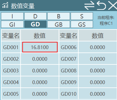
Click Variables - Global Numeric to enter the global numeric variable interface.
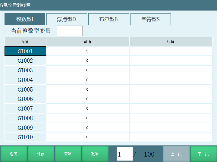
[Modify] Select the variable to modify, click "Modify" to assign a value and add a comment to the variable.
[Clear] Clear the stored value in the variable. After clicking clear, the variable value becomes 0. The clear button only clears the values on the current interface.
[Cancel] No operation on the selected variable.
[Save] Save the modified variable value.
[Return] Return to the variable interface.
How to Assign Values to Global Numeric Variables?
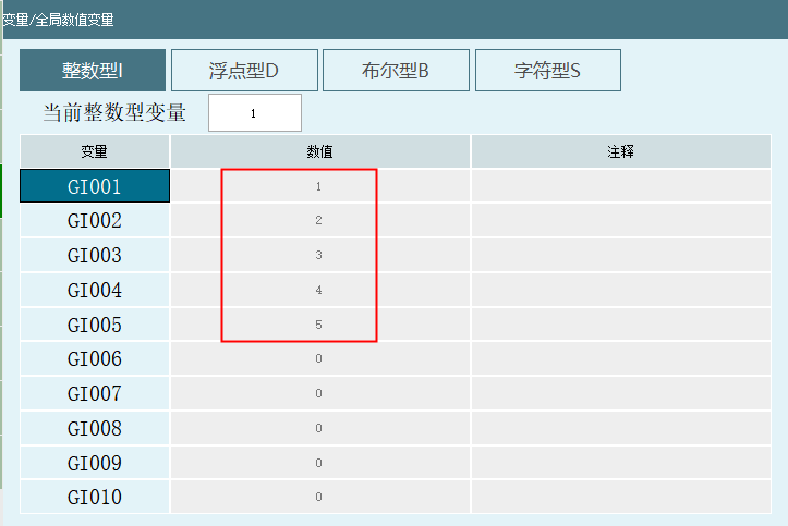
Manual Assignment
- In the global numeric variable interface, select the variable to modify, click "Modify" and enter the value.
- Click "Save" to complete the variable assignment.
Instruction Assignment
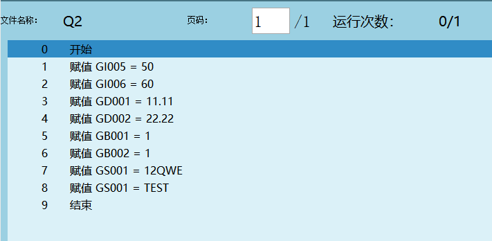
- Create a new project and open the project file.
- Insert an instruction, select Variable type for instruction type, and select the assignment instruction.
- Click [OK] to enter the instruction parameter setting interface, select the variable type and fill in the variable value.
- Click [OK] to insert the assignment instruction successfully. If you need to assign values to multiple different variables, repeat the previous steps.
- After the instruction executes, you can view the variable value in the Monitor - Numeric Variable interface or Global Numeric Variable interface.
Global Numeric Variable Types
Global Integer
| Item | Description |
|---|---|
| Format | GINT |
| Range | [1, 999] |
| Variable | Variable number |
| Value | Variable value, integer variable range is integers |
| Comment | Users can add comments to variables to mark the variable's purpose |
Global Float
| Item | Description |
|---|---|
| Format | GDOUBLE |
| Range | [1, 999] |
| Variable | Variable number |
| Value | Variable value, float variable range is real numbers |
| Comment | Users can add comments to variables to mark the variable's purpose |
Global Boolean
| Item | Description |
|---|---|
| Format | GBOOL |
| Range | [1, 999] |
| Variable | Variable number |
| Value | Variable value, boolean variable range is 0/1 |
| Comment | Users can add comments to variables to mark the variable's purpose |
Global String
| Item | Description |
|---|---|
| Format | GSTRING |
| Range | [1, 999] |
| Variable | Variable number |
| Value | Global string can store numbers, symbols, letters (including upper and lower case), and Chinese characters |
| Comment | Users can add comments to variables to mark the variable's purpose |
Local Numeric Variables
| Variable Type | Numeric Type | Variable Count | Variable Example |
|---|---|---|---|
| Local Integer | INT | 999 | I001...I999 |
| Local Float | DOUBLE | 999 | D001...D999 |
| Local Boolean | BOOL | 999 | B001...B999 |
| Local String | STRING | 999 | S001...S999 |
Description:
- Values assigned to local numeric variables only affect the current program. Example: Create Program A and Program B. In Program A, assign I001=10, then open Program B and check I001 in the variable interface. The variable interface shows I001=0.
- All defined local numeric variables can generally only be used in the current program. Other programs and background programs cannot use them.
Note: When using instructions to call background subprograms, declaring local numeric variable parameters allows them to be used in the main program.
To define local variables, click [Variables] in the open program interface to enter the local variable parameter setting interface.
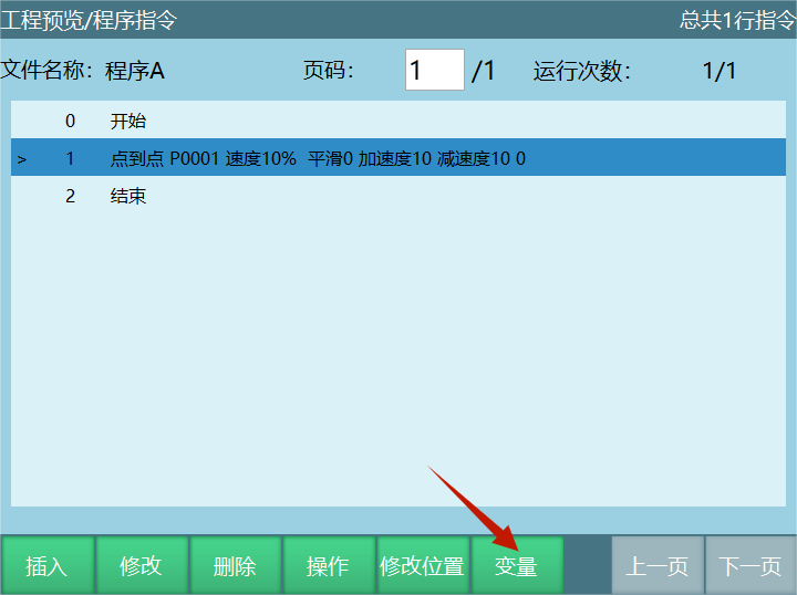
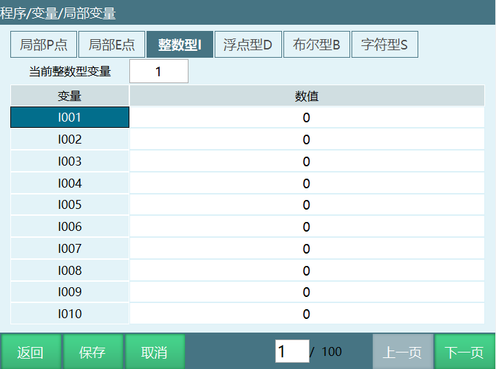

[Modify] Modify the variable value of the selected number.
[Save] After modifying the target variable value, click save to successfully modify the variable value.
[Cancel] No operation on the selected variable.
[Return] Click the return button to return to the program interface.
Enter a value and click OK on the keypad to directly locate the corresponding variable. For example, entering 9 will directly locate I009.
How to Assign Values to Local Numeric Variables
Manual Assignment
- In the Program - Variables - Local Variables interface, click [Modify] to enter the value for the variable to be assigned.
- Click [Save] to successfully modify the variable.
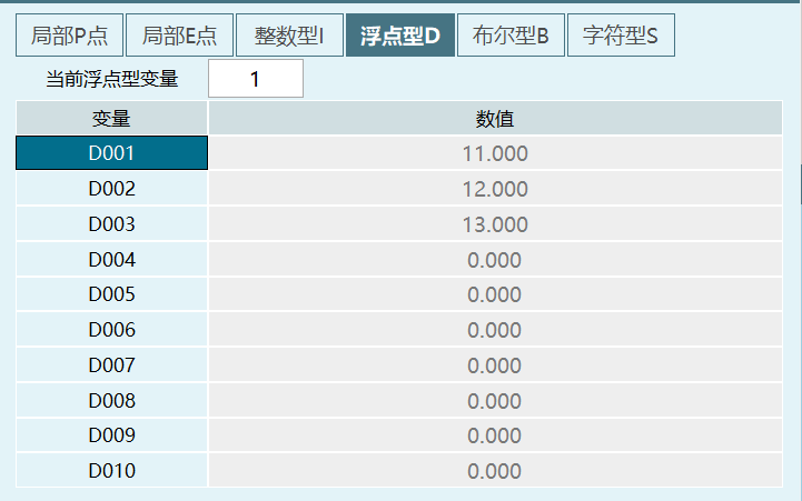
Note: Values assigned to variables manually are considered the initial values of the variable. Values assigned via instructions do not modify the initial values. The variable value display in the local variable interface remains unchanged unless the user manually modifies the initial value again.
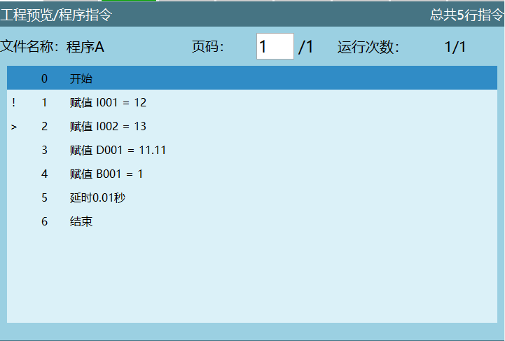
Example: If we assign D001=22.22 via instruction, after the instruction finishes running, checking D001 in this interface shows D001=11.11.
Instruction Assignment
- Create a new project and open the project file.
- Insert an instruction, select Variable type for instruction type, and select the assignment instruction.
- Click [OK] to enter the instruction parameter setting interface, select the variable type and fill in the variable value.
- Click [OK] to insert the assignment instruction successfully. If you need to assign values to multiple different variables, repeat the previous steps.
- During instruction execution, you can monitor variable value changes in the Monitor - Numeric Variable interface.
Using Numeric Variables
Numeric variables are used in various processes, functions, and instructions.
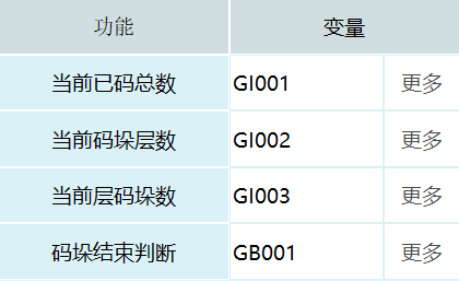
- Process Usage: In the palletizing process, variables are used to record the number of palletizing layers, the number of palletizing items, and the number of items in the current layer.
- Modbus Master Function: After successful communication, insert a Modbus instruction, assign values to variables, and execute the Modbus write instruction to write the assigned variable values.
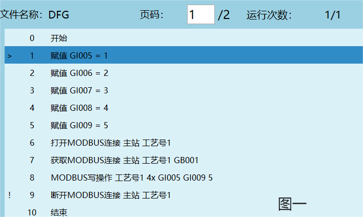
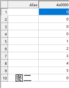
- Instruction Usage:
- Timer instructions use bound variables for timing.
- Conditional judgment instructions use variables as judgment conditions.
- Position variable instructions can add, subtract, or modify positions through variable assignment. Motion control and program control instruction types also use the variable binding function.
Numeric Variable Application Examples
Conditional Instruction Application
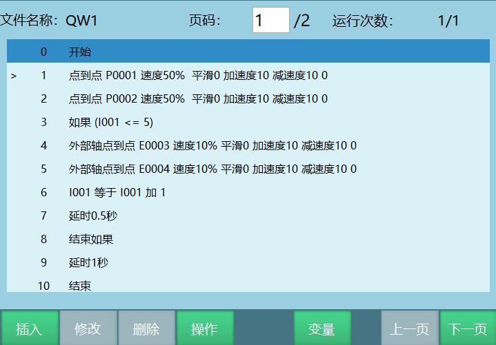
Example: Insert an IF instruction. The judgment condition is that when I001<=5, execute the instructions inside the IF statement. When I001>5, exit the IF statement and execute the instructions after ENDIF.
Timer Instruction Application
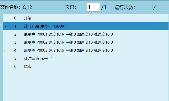
When the program is running, the timer instruction can store the program running time into a variable.
Position Variables
Global Position Variables
| Type | Count | Example |
|---|---|---|
| GP: Variable that records robot position data | 9999 | GP0001...GP9999 |
| GE: Variable that records position data of two robots in dual-robot mode | 9999 | GE0001...GE9999 |
| Position variable that records external axis positions when external axes are connected | 9999 | GE0001...GE9999 |
Click Variables - Global Position to enter the global position interface.
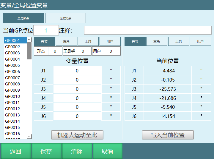
- [Modify] Manually modify the target variable position. Click modify, fill in the parameters, and click OK on the keypad.
- [Save] After modifying the position, click save to successfully modify the position.
- [Clear] Clear the target variable position information. After clicking save, the position data is cleared successfully.
- [Cancel] Cancel the modification and clear operations on the target variable.
- [Return] Return to the variable interface.
- Current GP Position / Current GE Position: Enter a value and click OK on the keypad to directly locate the corresponding variable. If you enter 100, it will directly locate GP0100.
- Comment: Add a comment to the variable to help users understand what each position variable represents.
- Variable Position: Store position information of different robot positions into the selected variable. When external axes are connected, it also records external axis position information. This parameter can be manually modified.
- Current Position: The robot's current position information. When external axes are connected, it also records the current external axis position information. This parameter cannot be modified.
- Move Robot to This Point: In teach mode, enable the servo, then click Move Robot to This Point. The robot moves to the target position.
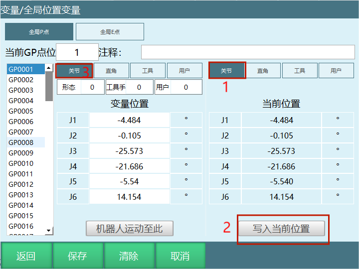
- Write Current Position: Click modify, then click Write Current Position to write the robot's current position information into the selected variable. To write the robot's current joint coordinates into the variable, select Joint first, then click Write Current Position. To write the robot's current Cartesian coordinates into the variable, select Cartesian first, then click Write Current Position. Click save to complete the write operation.
Global Position Variable Modification
Manual Modification
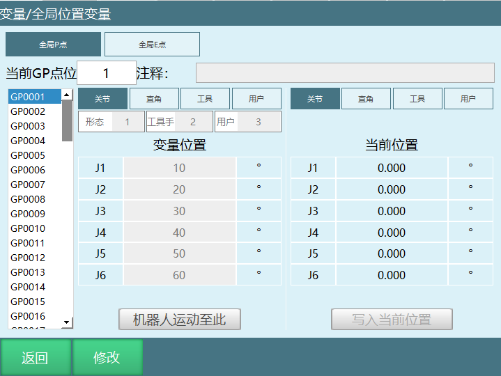
- Click [Modify], select the variable to modify, then assign values to each axis in the variable position. If you need to modify configuration, tool, or user parameters, fill in the appropriate values in the corresponding input fields.
- Click [Save] to successfully modify the variable position information.
Write Robot Current Position Modification
- In teach mode, jog the robot to the target position, then click [Modify].
- Click Write Current Position.
- Click [Save] to successfully modify the target variable.
Target Position Description
Modify Global GP Point in Parameter Interface
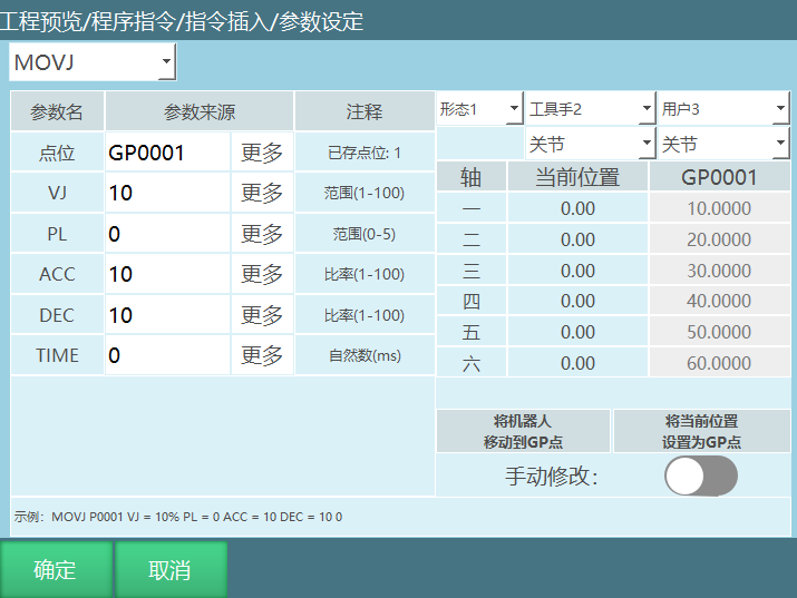
Set current position as target position:
- Insert a motion instruction and select the GP variable for the position.
- Move the robot to the target variable position, then click [Set Current Position as GP Point] to write the robot's current coordinates into the variable.
- A prompt will appear asking "Continue modifying position?". Click [OK] to store the current position into the target variable. Click [Cancel] to not record the robot's current position to the target variable. You can continue moving the robot to the desired position. The "Current Position" in the parameter interface changes as the robot moves.
Set manual position as target position (the manual modification button must be opened for the target position to be modified successfully):
- Insert a motion instruction and select Global GP Point for the position type.
- In the parameter setting interface, click [Set Manual Position as GP Point], modify the target variable axis positions, fill in the required coordinate values. A prompt will appear asking "Continue modifying position?". Click [OK] to store the modified position into the target variable. Click [Cancel] to continue modifying the target axis position.
Notes:
- Global position variables can be directly called in different job files.
- The GP point position information modified in the global position variable interface and the parameter setting interface are synchronized.
- If Program A inserts GP0001 and GP0002, and Program B also inserts GP0001 and GP0002, the positions of GP0001 and GP0002 in both programs are the same. If the two positions in Program A are modified, the positions in Program B will also be modified, which may cause issues when Program B runs.
- It is recommended not to call the same global GP points in different job files. Otherwise, if one job file modifies the global position information, the same global GP points called in other job files will also be modified, which may cause issues when other job files run.
Local Position Variables
| Type | Count | Example |
|---|---|---|
| P: Variable that records robot position data | 9999 | P0001...P9999 |
| E: Variable that records position data of two robots in dual-robot mode | 9999 | E0001...E9999 |
| Position variable that records external axis positions when external axes are connected | 9999 | E0001...E9999 |
Click [Project] - select [Program] - in the program interface click [Variables] to enter the local position variable interface.
Note: Local position variable P can only be used in a single job file and cannot be called across all job files.
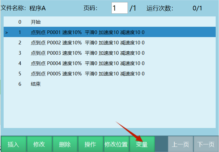
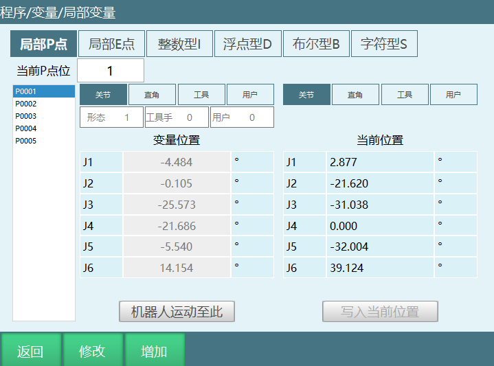
Button descriptions in the figure:
- [Modify] Manually modify the target variable position. Click modify, fill in the parameters, and click OK on the keypad.
- [Return] Return to the program instruction interface.
- [Save] After modifying the position, click save to successfully modify the position.
- [Add] Select a local P point, click Add to create a new P point; select a local E point, click Add to create a new E point. For example: if the current local P point count is at P0006, clicking Add will change the count to P0007.
- [Cancel] No modification to the original variable position information.
- Current P Position / Current E Position: Enter a value and click OK on the keypad to directly locate the corresponding variable. For example, entering 5 will directly locate P0005.
- Variable Position: Store position information of different robot positions into the selected variable. When external axes are connected, it also records external axis position information. This parameter can be manually modified.
- Current Position: The robot's current position information. When external axes are connected, it also records the current external axis position information. This parameter cannot be modified.
- Move Robot to This Point: In teach mode, enable the servo, then click Move Robot to This Point. The robot moves to the target position.
- Write Current Position: Click modify, then click Write Current Position to write the robot's current position information into the selected variable. To write the robot's current joint coordinates into the variable, select Joint first, then click Write Current Position. To write the robot's current Cartesian coordinates into the variable, select Cartesian first, then click Write Current Position. Click save to complete the write operation.
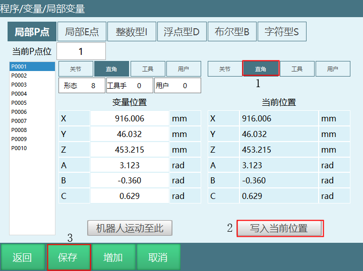
Local Position Variable Modification
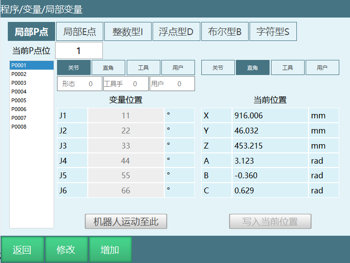
Manual Modification
- Click [Modify], select the variable to modify, then assign values to each coordinate axis in the variable position. If you need to modify configuration, tool, or user parameters, fill in the appropriate values in the corresponding input fields.
- Click [Save] to successfully modify the variable position information.
Instruction Local Variables
Add, Subtract, and Modify Local Instructions
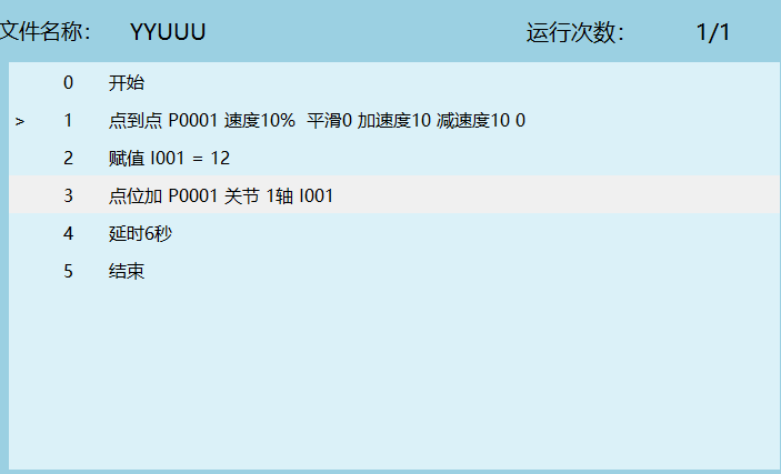
Program Description:
Assume P0001 joint coordinates (3.6847, 0, 0, 0, 0, 0)
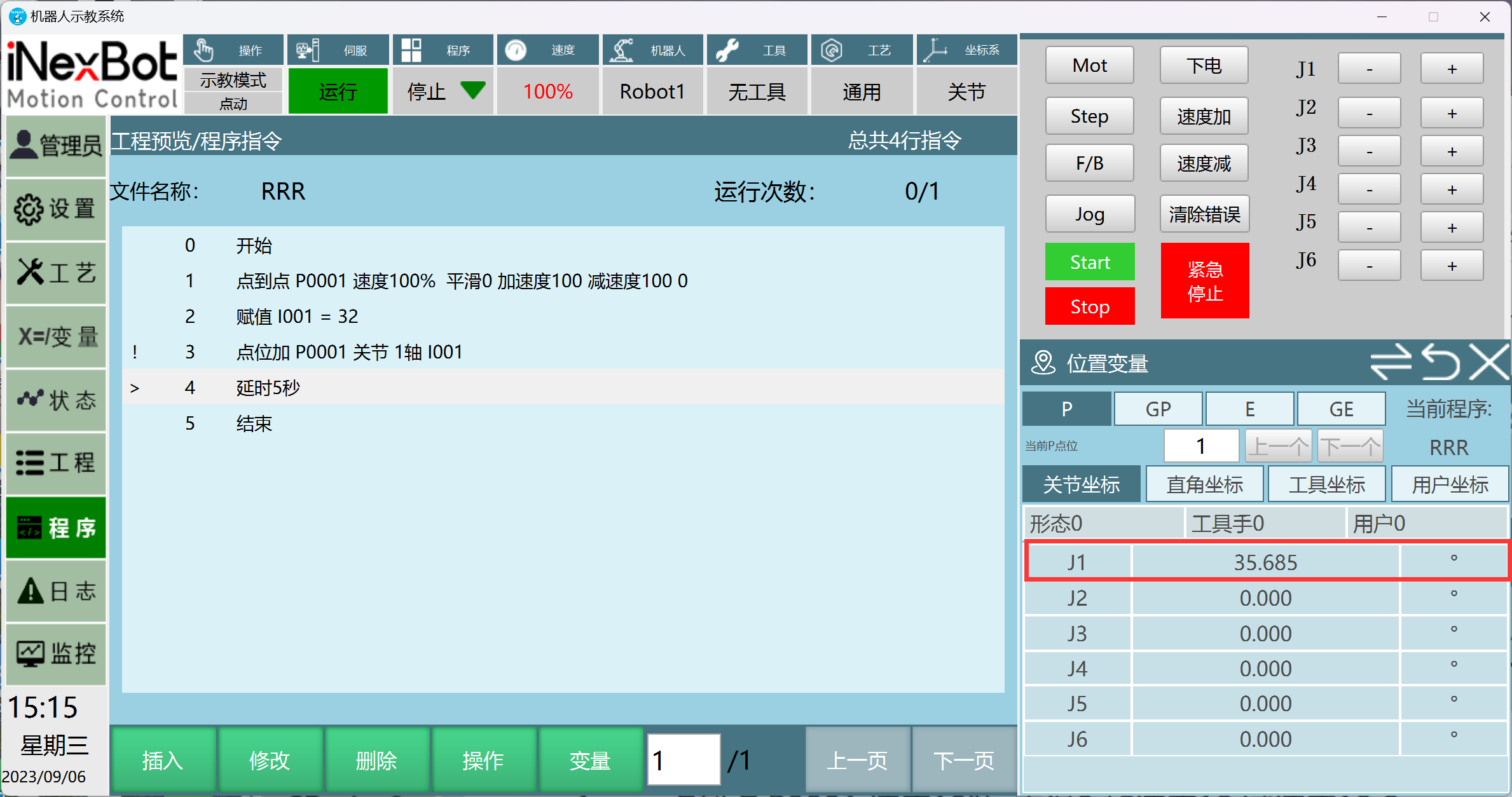
When the program runs to line 3, P001 displays (35.6847, 0, 0, 0, 0, 0) in Monitor - Position Variables - Joint Coordinates
After the program finishes running, enabling the servo shows P001 joint coordinates (3.6847, 0, 0, 0, 0, 0)
Note: The P001 position in item 1 of the program description can be considered the initial position of the target point. The value modified through addition and subtraction on the target point can be understood as an additional value. For example: the 32 added to P001 joint J1 axis is the additional value.
After the program finishes running, the P0001 position coordinates return to the initial position coordinates.
As shown in the figure, there are now 3 instructions with no local variables set. When the program starts running.
Start executing the first instruction: Click Monitor - Position Variables, the position variable displays the coordinate value of P001.
P0001 Initial Position
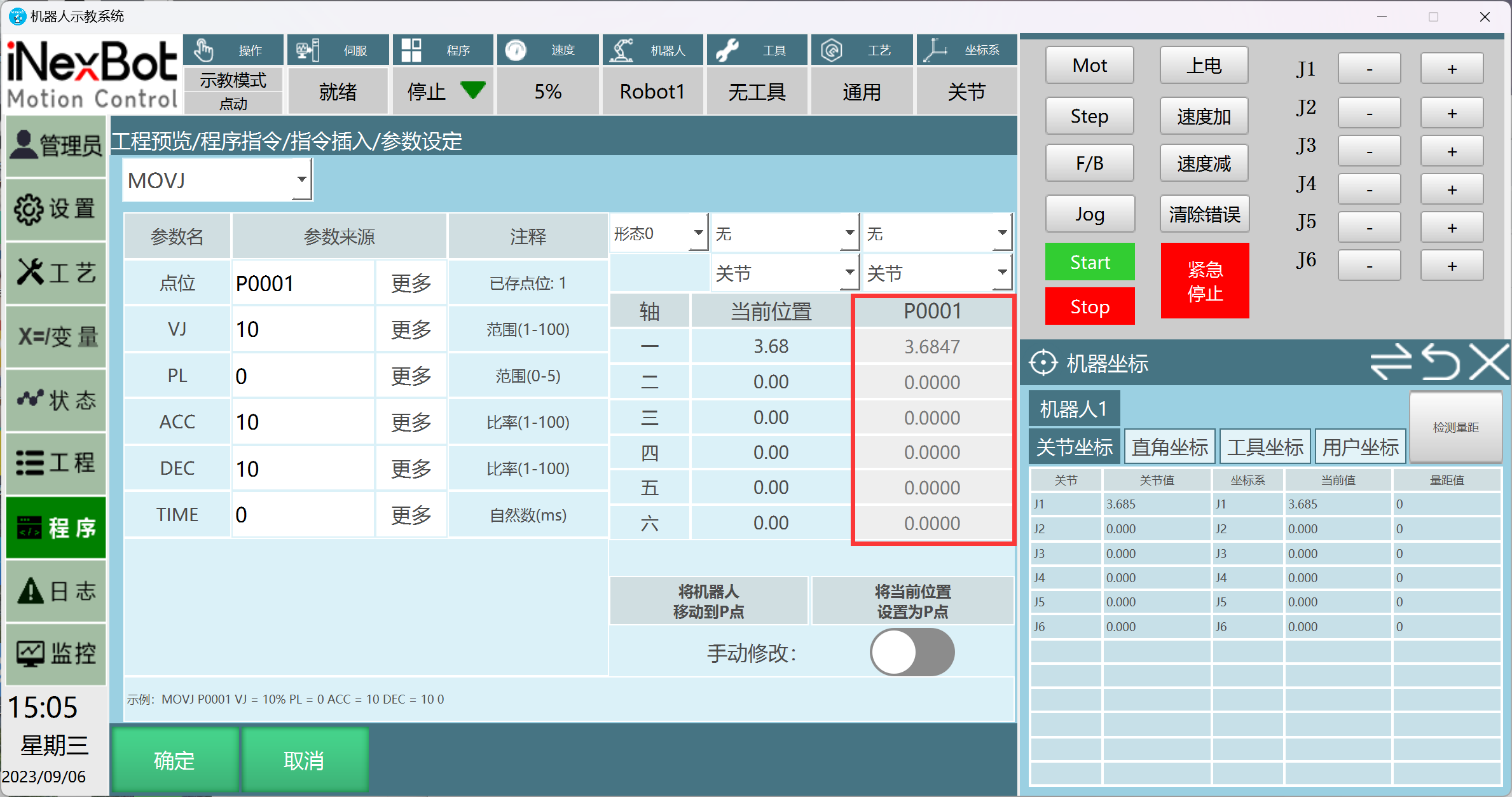
P001: Initial Position + Additional Value Position Coordinates Display
P001 Position Coordinates Display After Program Finishes Running
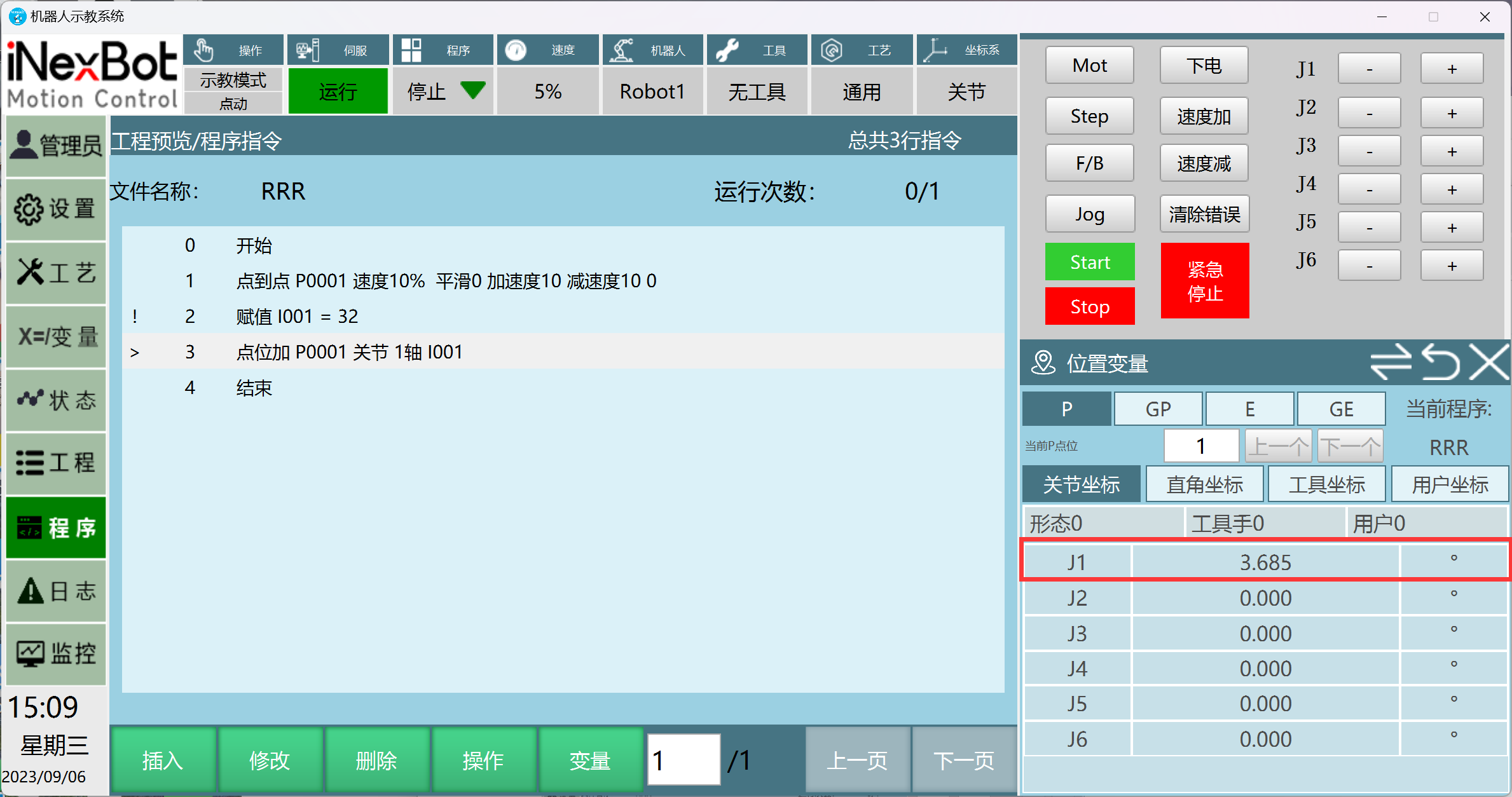
Note: For global positions (GP), if the same instructions as shown above are inserted, performing add, subtract, and modify operations on the target position will change the target position to the modified position.
Write Robot Current Position Modification
- In teach mode, jog the robot to the target position, then click [Modify].
- Click Write Current Position.
- Click [Save] to successfully modify the target variable.
Modify Local P Point in Parameter Interface
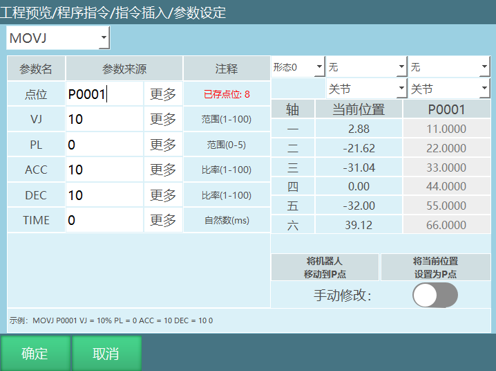
Set current position as target position:
- Insert an instruction and select the target variable.
- In the parameter setting interface, move the robot to the target variable position, then click [Set Current Position as P Point] to write the robot's current coordinates into the variable.
- A prompt will appear asking "Continue modifying position?". Click [OK] to store the current position into the target variable. Click [Cancel] to not record the robot's current position to the target variable. You can continue moving the robot to the desired position.
Set manual position as target position (the manual modification button must be opened):
- Insert a motion instruction and select P Point for the position type.
- In the parameter setting interface, click [Set Manual Position as P Point], modify the target variable axis positions, fill in the required coordinate values. A prompt will appear asking "Continue modifying position?". Click [OK] to store the modified position into the target variable. Click [Cancel] to continue modifying the target axis position.
Notes:
- The position information in the local position variable interface and the parameter setting interface are synchronized.
- When inserting a motion instruction, if you select New for the position, a new P point will be created (selecting New directly does not allow modifying position information; you must click [OK] in the parameter setting interface, then click [Modify] in the program instruction interface to modify position information). If you select P directly, choose the P point within the existing position count range.
- Defined local variables only take effect in the current job file. Example: If both Program A and Program B define P0001, modifying P0001's position in Program A will not modify P0001's position in Program B.
Position Configuration, Tool, and User Value Modification Methods
Settings - Operation Parameters interface adds position configuration, tool, and user value setting methods, with two modes: Auto and Manual. Default is Auto.
Auto
When creating a new position, the configuration, tool, and user coordinate default to the current values.
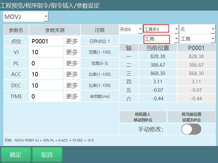
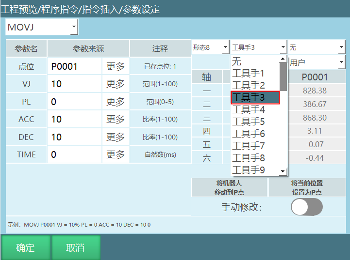
To modify the tool, select Tool for the current position, click [Set Current Position as P Point], and the tool is modified successfully.
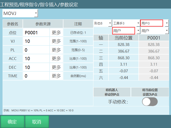
To modify the user coordinate: Select User for the current position, click [Set Current Position as P Point] and the user coordinate is modified successfully.
Configuration value: Cannot be modified, obtained automatically.
Manual
Manually set configuration, tool, and user coordinates.
- New position: Can directly modify configuration, tool, and user coordinates. Modify tool: Select the tool to modify, click [Set Current Position as P Point], click [OK] in the prompt to successfully modify the tool. Modify user coordinate and configuration using the same method as modifying the tool. Click [Set Current Position as P/GP] to not change the existing configuration, tool, and user values of the current position.
- Instruction - Position Variables - Set Position Information, can modify coordinate system, configuration, etc.
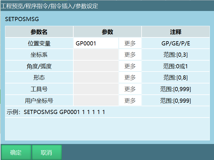
- Position Variable: Select the position GP/GE/P/E to modify. Only existing positions can be selected.
- Coordinate System: Range [0, 3]; 0: Joint coordinate system; 1: Cartesian coordinate system; 2: Tool coordinate system; 3: User coordinate system.
- Angle/Radian: Selectable values 0/1.
- Configuration: Range [0, 8].
- Tool Number: Tool number [0, 999].
- User Coordinate Number: User coordinate system [0, 999]. Click OK and run the program to apply the changes.
Position Variable Position Information
Position Coordinate System
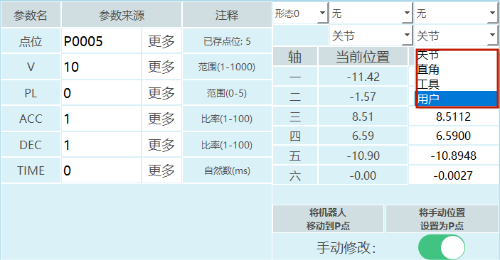
Range [0, 3]: 0 for joint coordinates, 1 for Cartesian coordinates, 2 for tool coordinates, 3 for user coordinates.
How to modify the coordinate system of a position variable?
- Global GP points: Click Variables - Global Position to enter the global position variable interface, click modify, select the coordinate system, click save to successfully modify the coordinate system.
- Local P points: In the program instruction interface, click Variables to enter the local position variable interface, click modify, select the coordinate system, click save to successfully modify the coordinate system.
- In the program instruction interface, select the global GP point or local P point to modify, click modify to enter the parameter setting interface, open the manual modification button, select the coordinate system, and click OK to successfully modify the coordinate system.
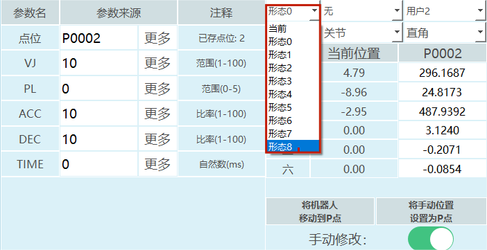
Configuration
Range: [0, 8].
- For 6-axis serial multi-joint robots, configuration parameters exist. If the configuration parameter is set to Current, the control system automatically calculates the robot's current configuration value through conversion. The configuration value is calculated from the joint positions of axes 1, 3, and 5. If the range is between [-90, +90], it is 1; otherwise, it is 0.
- The configuration value is the binary conversion of the positions of axes 1, 3, and 5 to decimal, then plus 1. Example: A six-axis robot with axis 1 at 59 degrees, axis 2 at 69 degrees, axis 3 at 79 degrees, axis 4 at 89 degrees, axis 5 at 99 degrees, axis 6 at 109 degrees. Result: Binary 110 = Decimal 6, configuration value is 6+1=7.
| Axis | Axis 1 | Axis 3 | Axis 5 |
|---|---|---|---|
| Binary Value | 1 | 1 | 0 |
- For four-axis SCARA robots, there is a left/right hand parameter.
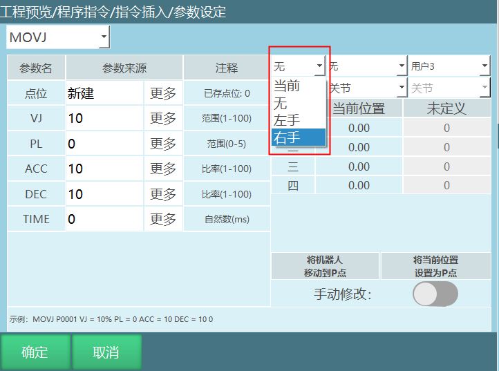
How to modify the position variable configuration?
- Global GP points: Click Variables - Global Position to enter the global position variable interface, click modify, enter the configuration value in the configuration column, click save.
- Local P points: In the program instruction interface, click Variables to enter the local position variable interface, click modify, enter the configuration value in the configuration column, click save.
- In the program instruction interface, select the global GP point or local P point to modify, click modify to enter the parameter setting interface, open the manual modification button, select the configuration, and click OK.
Tool
Range [0, 999].
How to modify the tool number of a position variable?
- Global GP points: Click Variables - Global Position to enter the global position variable interface, click modify, enter the tool number in the tool column, click save to successfully modify the tool parameter.
- Local P points: In the program instruction interface, click Variables to enter the local position variable interface, click modify, enter the tool number in the tool column, click save to successfully modify the tool.
- In the program instruction interface, select the global GP point or local P point to modify, click modify to enter the parameter setting interface, open the manual modification button, select the tool, and click OK to successfully modify the tool.
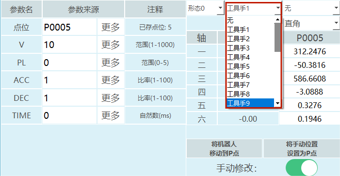
Note: When the target position coordinates are Cartesian, tool, or user coordinates, if you want to bind the target position to a tool, select the corresponding tool. If not binding, select None. If the actual tool during motion differs from the tool bound to the position, the program will report an error during runtime.
Example: Target position binds tool 2, but the actual tool used is tool 1. When running the instruction, the controller reports an error (Robot 1 tool coordinate usage error, position tool is 1, actual tool is 2).
User Coordinate
Range [0, 999].
How to modify the user coordinate number of the target position?
- Global GP points: Click Variables - Global Position to enter the global position variable interface, click modify, enter the user coordinate number in the user column, click save to successfully modify the user coordinate number.
- Local P points: In the program instruction interface, click Variables to enter the local position variable interface, click modify, enter the user coordinate number in the user column, click save to successfully modify the user coordinate number.
- In the program instruction interface, select the global GP point or local P point to modify, click modify to enter the parameter setting interface, open the manual modification button, select the user, and click OK to successfully modify the user coordinate number.
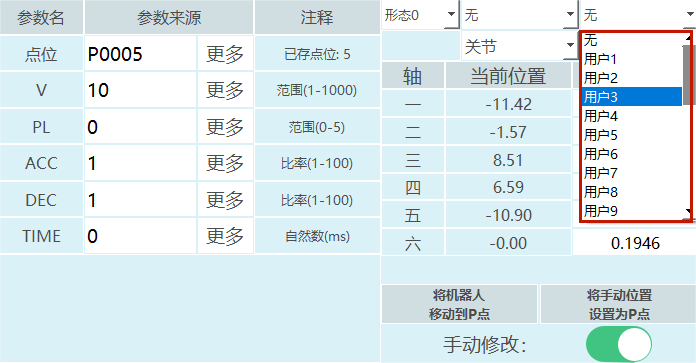
Note: When the target position coordinates are user coordinates, if you want to bind the target position to a user coordinate, select the corresponding user number. If not binding, select None. If the actual user during motion differs from the user bound to the position, the program will report an error during runtime.
Example: Target position binds user 1, but the actual user used is user 2. When running the instruction, the controller reports an error (Robot user coordinate usage error, position user is 1, actual user is 2).
Angle/Radian
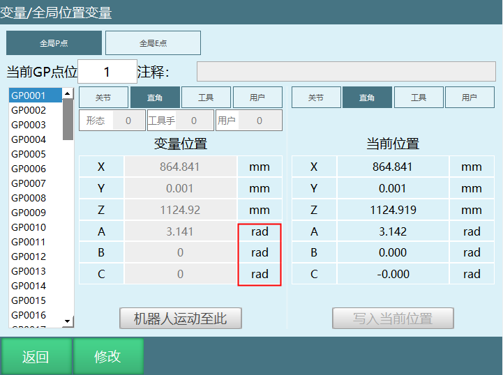
The robot has attitude axes A, B, C in Cartesian, tool, and user coordinate systems. The attitude values of the attitude axes can be manually modified.
How to modify angle/radian?
Click Settings - Operation Parameters to enter the operation parameter interface, click modify, and set the angle and radian systems in the attitude value column.
Example: After modifying the attitude value to angle value, the units of A, B, C axes in Cartesian, tool, and user coordinate systems change to degrees (°); after modifying to radian value, the units change to radians (rad).
Local P Point Position Information Description
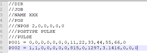
Example: P0002 = 1,1,0,0,0,0,0,815,0,1297,3.1416,0,0,0.
Position data breakdown:
| P0002 | Position Parameter | Parameter Description |
|---|---|---|
| 1 | Coordinate System | 0: Joint 1: Cartesian 2: Tool 3: User |
| 1 | Angle/Radian | 0: Angle (joint point) 1: Radian (Cartesian, tool, user point) |
| 0 | Configuration/Left-Right Hand | Configuration parameter for six-axis, left-right hand parameter for four-axis SCARA |
| 0 | Tool | Tool number |
| 0 | User | User coordinate number |
| 0 | Reserved | Reserved |
| 0 | Reserved | Reserved |
| 815 | Axis 1 | Position axis 1 coordinate |
| 0 | Axis 2 | Position axis 2 coordinate |
| 1297 | Axis 3 | Position axis 3 coordinate |
| 3.1416 | Axis 4 | Position axis 4 coordinate |
| 0 | Axis 5 | Position axis 5 coordinate |
| 0 | Axis 6 | Position axis 6 coordinate |
| 0 | Axis 7 | Position axis 7 coordinate |
Local E Point Position Information Description
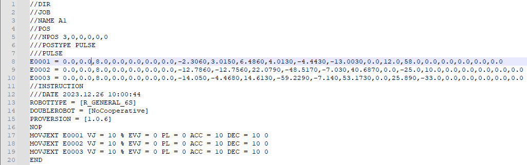
Example: E0001 position data breakdown:
| E0001 | Position Parameter | Parameter Description |
|---|---|---|
| 0 | Coordinate System | 0: Joint 1: Cartesian 2: Tool 3: User |
| 0 | Angle/Radian | 0: Angle (joint point) 1: Radian (Cartesian, tool, user point) |
| 8 | Configuration/Left-Right Hand | Configuration parameter for six-axis, left-right hand parameter for four-axis SCARA |
| 0 | Tool | Tool number |
| 0 | User | User coordinate number |
| 0 | Reserved | Reserved |
| 0 | Reserved | Reserved |
| -2.3060 | Axis 1 | Position axis 1 coordinate |
| 3.0150 | Axis 2 | Position axis 2 coordinate |
| 6.4860 | Axis 3 | Position axis 3 coordinate |
| 4.0130 | Axis 4 | Position axis 4 coordinate |
| -4.4430 | Axis 5 | Position axis 5 coordinate |
| -13.0030 | Axis 6 | Position axis 6 coordinate |
| 0 | Axis 7 | Position axis 7 coordinate |
| 12.0 | O1 | Position O1 axis coordinate |
| 58.0 | O2 | Position O2 axis coordinate |
| 0 | O3 | Position O3 axis coordinate |
| 0 | O4 | Position O4 axis coordinate |
| 0 | O5 | Position O5 axis coordinate |
Variable Instructions
"√" indicates support for this instruction.
| Instruction Type | Foreground | Global Background | Local Background |
|---|---|---|---|
| Assignment | √ | √ | √ |
| Write to File | √ | √ | √ |
SET - Assignment
Format: SET [Variable Name] I001 [Selected Target Variable] 3 [Value to Assign].
Function: Assign values to defined integer, float, boolean, and string variables.
Parameters: For detailed reference variable introduction, see the reference variables chapter.
| Parameter | Parameter Description |
|---|---|
| Variable | Click More to select the required variable type (integer, float, boolean, and string) |
| Variable Value | Assign a value to the above variable, can be manually entered or selected as a variable |
Example:
NOP
SET I001=12
SET D001=12.21
SET GI012=100
SET GI[GI012]=999
END
Example: Lines 1 and 2 directly assign values to the selected variables. Lines 4 and 5 assign values through variable form. After the program finishes running, I001=12, D001=12.21, GI100=999.
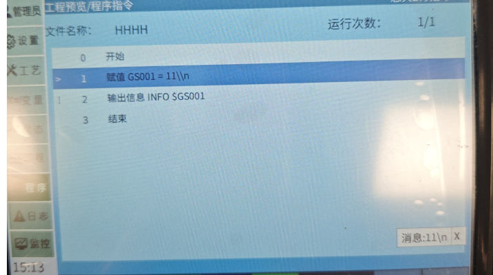
If the SET string type contains escape characters and you want to avoid the impact of escape characters on the string, you can add "" before the escape character. String types have similar issues.
Example:
SET GS001=11\n: Here "\n" is treated as an escape character.
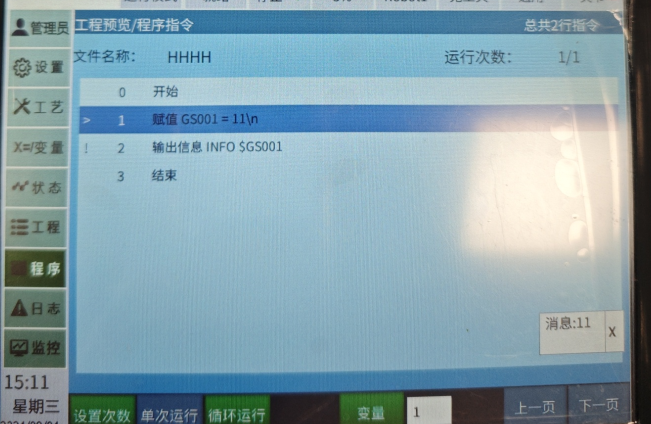
Can be modified to: SET GS001=11\n: This allows normal printing.
Escape Character Reference Table
FORCESET - Write to File
Format: FORCESET [Instruction Name] GI001 [Variable Name to Write to File].
Function: Store buffered data to disk.
During program execution, all calculation and assignment operations modify values in the buffer and do not save to system files. To forcefully write global numeric variables from memory to files, use the FORCESET instruction.
Parameters:
| Parameter | Parameter Description |
|---|---|
| Variable Name | Click More to select the variable name to forcefully write to file |
Example:
NOP
GI001=10
FORCESET GI001
END