Wafer Process
1. Process Introduction
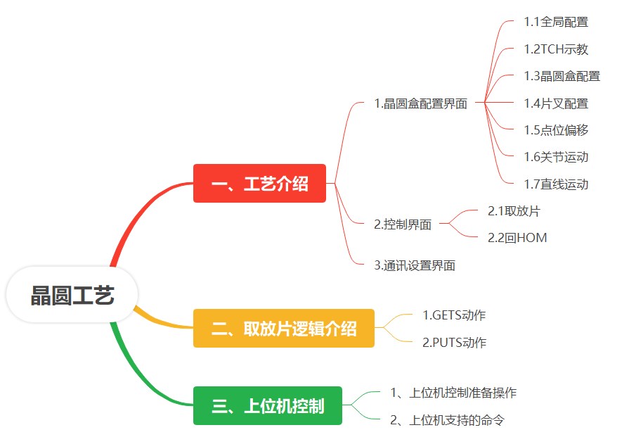
The wafer process is mainly used to enable wafer robots to transport and transfer wafers in semiconductor processing equipment. Its content mainly includes three modules: wafer cassette parameter configuration, manipulator control, and host computer control communication settings.
Under the wafer process, there are three interfaces: wafer cassette configuration interface, control interface, and communication settings interface.
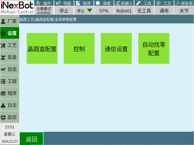
Wafer Cassette Configuration: Configures wafer cassette (FOUP) parameters including quantity, type, size, capacity, position, and pick/place operation parameters.
Control: Operates the manipulator and manually debugs the wafer process logic.
Communication Settings: Configures host computer communication parameters for controlling the manipulator.
1.1 Global Configuration Interface
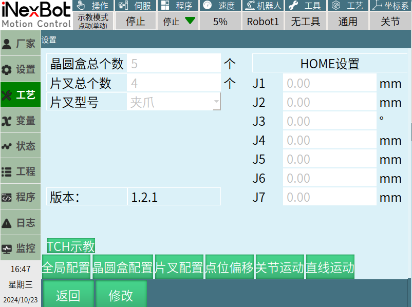
- Wafer Cassette Total Count: Range [1, 99], default 25.
- Fork Total Count: Range [1, 4], default 4.
- Fork Model: Gripper or Suction.
- HOM Settings: Safe starting position. Joint range: J1,J2,J4-J7 [-20000,20000]mm; J3 [-500,5000]°.
1.2 TCH Teaching Interface
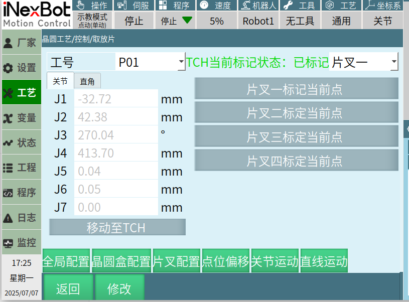
Marks wafer cassette position coordinates. TCH status: Unmarked/Marked.
1.3 Wafer Cassette Configuration Interface
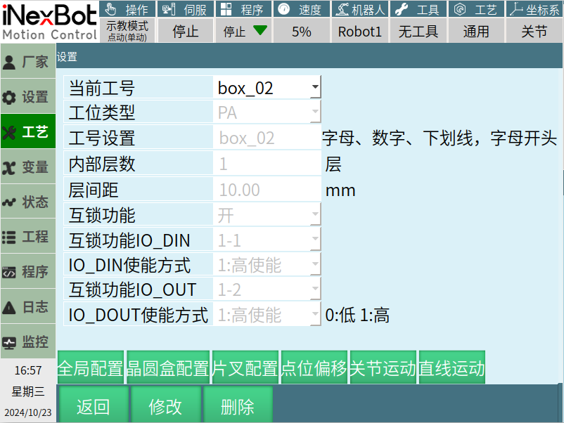
Configures station type (PA/Cassette), internal layers [1,99], layer spacing [1,1000]mm, interlock function with IO settings.
1.4 Fork Configuration Interface
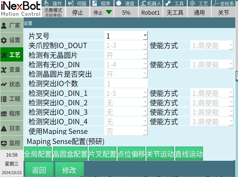
Configures gripper control IO, wafer presence detection, and wafer protrusion detection sensors.
1.5 Position Offset Interface
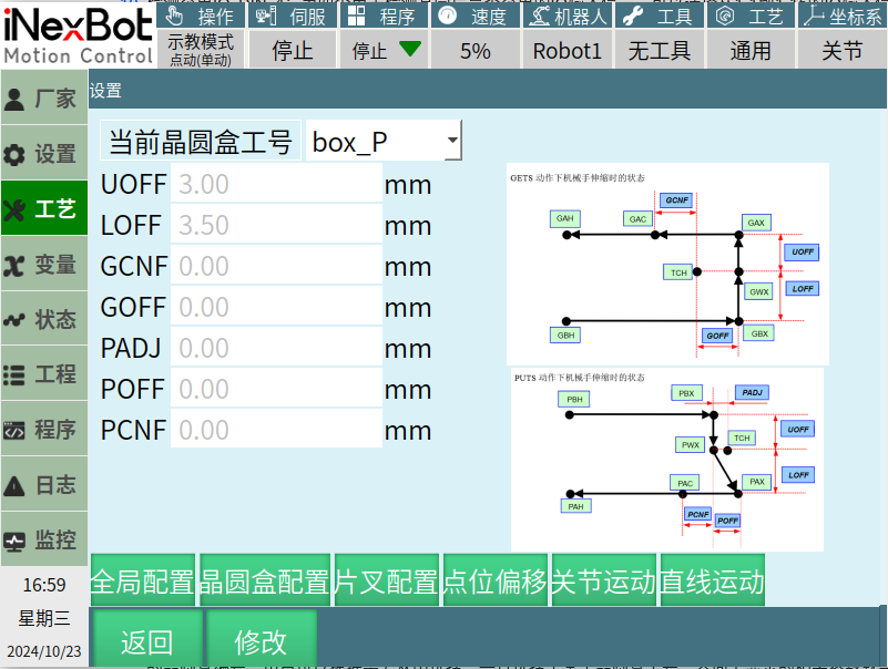
Configures UOFF, LOFF, GCNF, GOFF, PADJ, POFF, PCNF offsets (range [0,15]mm, default 3mm).
1.6 Joint Motion Interface
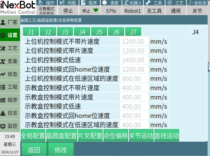
Configures maximum speed for each joint under various conditions (host/teach mode, with/without wafer, low speed, return to HOM).
1.7 Linear Motion Interface
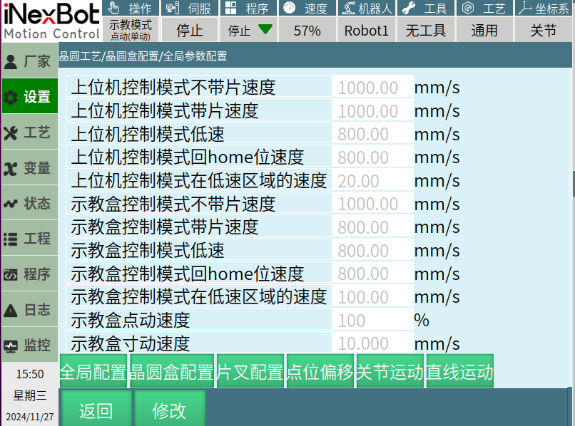
Configures maximum end-effector linear speed. Range [1,5000]mm/s.
2. Control Interface
2.1 Pick and Place Interface: Select wafer cassette, layer, action (GETS/PUTS/MOVP), and fork.
2.2 Return to HOM Interface: ALL or specific forks return to HOM.
3. Communication Settings
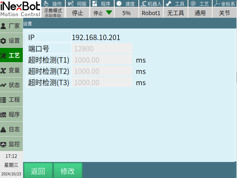
Configures IP, port [1,65535], timeout detection T1/T2/T3 [1,1000000]ms.
4. Auto Find Zero Configuration
Two retreats, two finds logic. One-key find zero, pause find zero, sequential return to zero supported.
2. Pick and Place Logic
GETS Action
TCH→GBH→Check wafer→Check interlock→GBX→GWX→Detect protrusion→GAX→GAC-GAH→Check wafer→Release interlock
PUTS Action
TCH→PBH→Check wafer→Check interlock→Detect protrusion→PBX→PWX→PAX→PAC-PAH→Check wafer→Release interlock
3. Host Computer Control
Supported commands: CSTA, GETS, PUTS, HOMH, HOMA, SENS, STAT, SERV, STOP, SSPD, RSPD, TCHP, SMOD, MOVP, MOVA, HOLD, RELS, RPOS, RXYZ, STCH, RTCH, CTCH, STXY, RTXY, RNST, CERR.
Appendix 7: Configuration Parameters
| Module | Parameter | Meaning |
|---|---|---|
| TCP | chars_time_out | Timeout |
| TCP | port | Port |
| IO | epsilon | Protrusion threshold (±0.3mm) |
| Grip | grip_type | 0:Forward, 1:Reverse |
| Hand | hand_sum | Hand count |
| Hand | hand_type | 0:Gripper, 1:Suction |
| Station | station_sum | Station count |
| Config | version | Version |