1 Safety Precautions and Product Assembly Instructions
1.1 Safety Precautions
The robot owner and operator must be responsible for their own safety. INEXBOT Technology is not responsible for the safety of robot usage. INEXBOT reminds users that safety equipment must be used when operating robots, and safety regulations must be followed.
Caution: Situations where the robot must NOT be used:
- Combustible environments;
- Environments with explosion risk;
- Environments with radio interference;
- In water or other liquids;
- Transporting people or animals;
- Do not cling to the robot;
- Other.
Safety Operating Procedures:
I. Manual and Jog Operation of the Robot
- Do not operate the teach pendant and control panel with gloves.
- Use a lower speed override when jogging the robot to increase control over the robot.
- Before pressing the jog button on the teach pendant, consider the robot's movement direction.
- Plan the path to avoid the robot's motion trajectory in advance, and confirm that the path is clear of interference.
- The area around the robot must be clean, free of oil, water, and debris.
II. Production Operation
- Before starting operation, you must know all the tasks the robot will execute according to the programmed instructions.
- You must know the positions and states of all switches, sensors, and control signals that affect robot movement.
- You must know the locations of emergency stop buttons on the robot control cabinet and peripheral control equipment, and be prepared to use these buttons in emergency situations.
WARNING
Never assume that the robot not moving means the program has finished, as the robot may be waiting for an input signal to continue moving!
Product Assembly
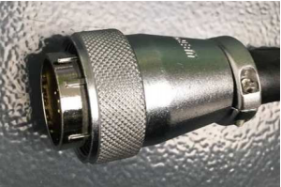
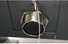
Teach Pendant Installation
The connector at the end of the teach pendant cable is shown in the figure, and the connection to the port below the control cabinet is shown in the figure:
1.2 Control Cabinet Installation
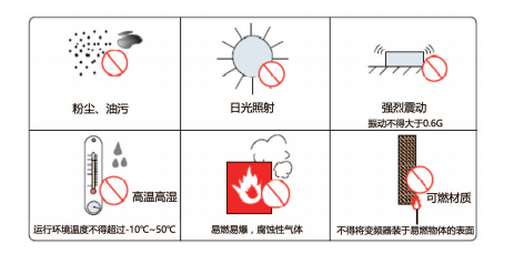
Installation Environment
- Ambient temperature: The surrounding ambient temperature has a significant impact on the controller lifespan. The operating environment temperature of the controller must not exceed the allowed temperature range (-10C to 50C).
- Install the controller vertically on a flame-retardant surface inside the installation cabinet, with sufficient space around it for heat dissipation.
- Install in a location that is not prone to vibration. Vibration should not exceed 0.6G. Pay special attention to keeping it away from equipment such as punch presses.
- Avoid installing in locations with direct sunlight, moisture, or water droplets.
- Avoid installing in locations with corrosive, flammable, or explosive gases in the air.
- Avoid installing in locations with oil stains or dust. The pollution level of the installation location should be PD2.
- NRC series products are designed for installation inside cabinets and need to be installed in the final system for use. The final system should provide corresponding fire protection enclosures, electrical protection enclosures, and mechanical protection enclosures, and comply with local laws, regulations, and relevant IEC standards, as shown in the figure:
1.3 Installation Location
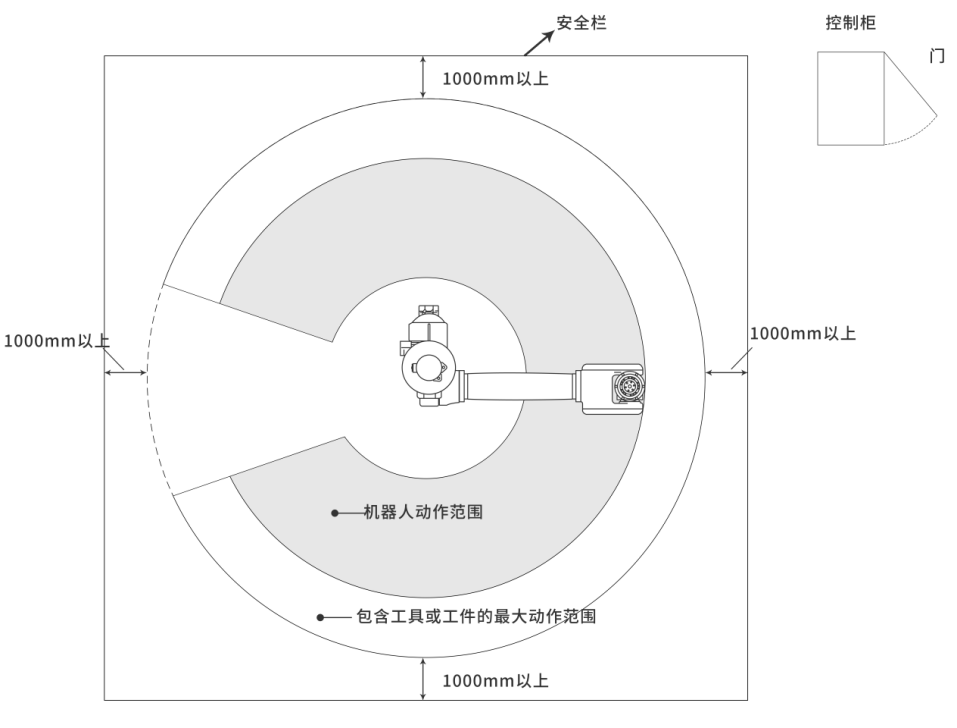
- The control cabinet should be installed outside the robot motion range (outside the safety fence).
- The control cabinet should be installed at a location where the robot movements can be clearly seen.
- The control cabinet should be installed at a location where the door can be opened for inspection.
- The control cabinet should be at least 500mm away from the wall to maintain a clear maintenance path.
1.4 Cable Requirements
Cable Classification:
Level 1: Sensitive signals (low-voltage analog signals, high-speed encoder signals, high-speed communication signals, +/-10V analog signals, low-speed 422/485 signals, digital input/output signals).
Level 2: Interference signals (low-voltage power supply, contactor control lines, motor cables with line filters, high-voltage AC power lines, motor cables without line filters).
For cable selection, symmetrically shielded cables are recommended for input/output main circuit cables. Compared with four-core cables, using symmetrically shielded cables can reduce the electromagnetic radiation of the entire conduction system.
Recommended power cable type -- Symmetrically shielded cable.
Recommended signal cable type -- Twisted pair shielded cable.
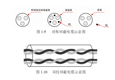
Note: Digital signal lines are recommended to use twisted pair shielded cables.
Recommended communication cable type -- Shielded communication cable, as shown in the figure:
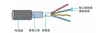
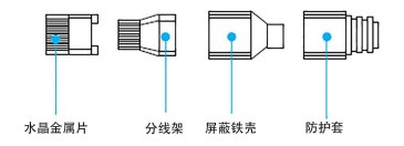
Note: The RJ45 connector used must have a shielded metal housing. The shield layer of the communication cable must be crimped together with the shielded iron housing of the RJ45 connector, as shown in the figure:
Wiring Requirements
- Power cables should be laid away from all signal cables.
- Motor cables, input power lines, and control circuit cables should not be routed in the same cable tray whenever possible.
- Avoid electromagnetic interference caused by coupling when motor cables and control circuits are routed in parallel over long distances.
- Maintain a minimum distance of 100mm between cables of different levels in the same cable tray.
Note:
- Cables of different levels should be routed separately. When routing long-distance cables in the same direction, maintain a minimum distance of 100mm between cables of different levels.
- Use a conductor as the backplane (use unplated zinc plate) and connect the metal parts of the controller directly to the backplane.
- Maintain cable separation according to levels. If cables of different levels must cross, they should cross at 90 degrees.
Grounding Requirements
WARNING
Please make sure to ground the grounding terminal, otherwise there is a risk of electric shock or malfunction due to interference!
I. Power line grounding requirements, as shown in the figure:
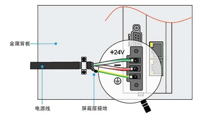
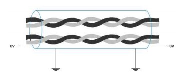
- Differential signal lines (CAN/RS485/RS422) use twisted pair shielded cables. The shield layer must be connected to 0V at both ends of the cable, as shown in the figure:
Wiring Precautions
- Personnel participating in wiring and inspection must be professional technicians with corresponding qualifications.
- The product must be reliably grounded. The grounding resistance should be less than 4 ohms. The neutral wire (zero line) must not be used as a substitute for the ground wire.
- Wiring must be correct and secure to avoid product failures or unexpected consequences.
- Surge absorption diodes connected to the product must be connected in the specified direction, otherwise the product may be damaged.
- Before unplugging connectors or opening the product chassis, the product power must be turned off.
- Avoid routing signal lines and power lines through the same conduit whenever possible. They should be separated by at least 30mm.
- Signal lines and encoder (PG) feedback lines should use multi-strand stranded wire and multi-core stranded shielded wire. For wiring length, command input lines should be a maximum of 3m, and PG feedback lines should be a maximum of 20m. The encoder signal wire is a group of twisted pairs, the power wire is a group of twisted pairs, and the battery wire is a group of twisted pairs.
- Do not frequently turn the power ON/OFF. When it is necessary to repeatedly turn the power ON/OFF, control it to less than once per minute. Because the power supply part of the servo unit contains capacitors, frequent ON/OFF will cause degradation of the main circuit components inside the servo unit.
- Confirm the power supply switching power supply power and voltage of the control system. Ensure that the power of the controller, teach pendant, and IO module is not less than 50W. For specific power requirements, refer to the IO module load.
- It is recommended to use separate switching power supplies for the servo and the controller system to prevent servo interference with the control system.
Note:
- The network cable connecting the control system and the servo must use Category 6A shielded network cable.
- If each axis corresponds to one servo, the network cable needs to be connected in the order of the axes.
- Please wire in the order of controller -- servo -- IO board.
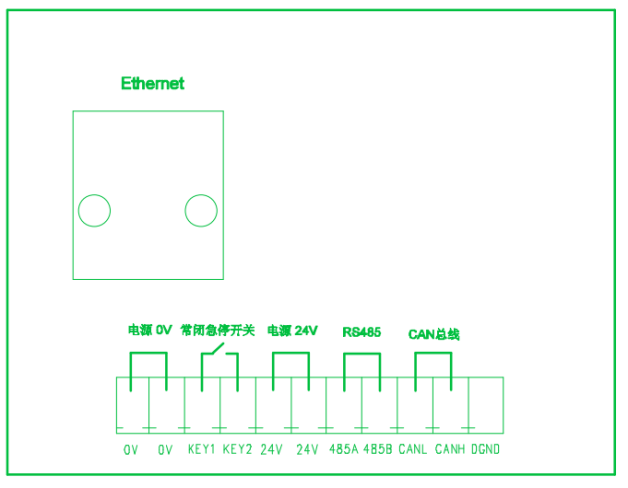
Teach Pendant Adapter Box Wiring Diagram
2 Teach Pendant Buttons and Interface Introduction
2.1 T30 Teach Pendant Physical Buttons
Left Side

Toggle current servo state

Switch current robot (only available in multi-robot mode)

Switch between current robot and external axis (only available when external axes exist)

Home return button

Return to safe point button

Clear servo error after alarm

Toggle drag mode (reserved)
Bottom Side

In teach mode, whether single-step program execution runs in forward or reverse order

Single-step program execution in teach mode

Decrease teach or run speed

Increase teach or run speed

Switch tool

Switch between four coordinate systems
Right Side

Pause program in run mode

Start program in run mode

Move corresponding axis in negative direction during teaching

Move corresponding axis in positive direction during teaching
Key Switch
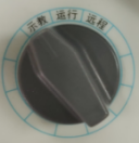
Left: Switch to teach mode
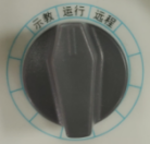
Middle: Switch to run mode
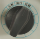
Right: Switch to remote mode
Emergency Stop Button
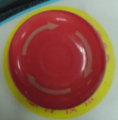
Press to activate emergency stop
Scroll Wheel Knob
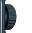
Rotate in program interface to switch to previous or next line
Deadman Switch
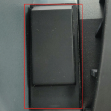
Three-position switch
Press to middle position to power on the robot
Press to bottom position to power off the robot
Release the switch to power off the robot
3 Operating System Introduction
3.1 Basic Description
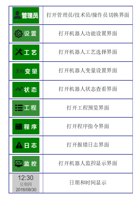
The left side of the interface shows function keys, as shown in the figure:
Permission Settings:
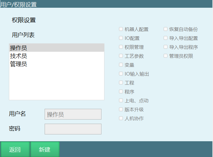
Switch user to administrator, select [Permission Settings], create a new user, and customize usage permissions:
3.2 Status Introduction
The top of the program shows the status bar, displaying various robot states;
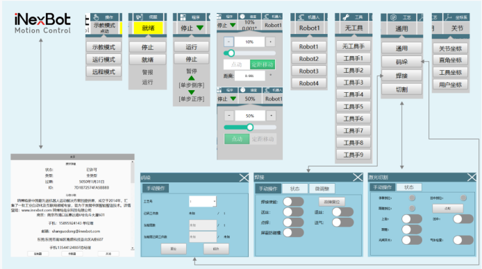
Mode State: Teach mode, Remote mode, Run mode. Can be switched by rotating the external knob.
Servo State: Stop, Ready, Running, Alarm
Switching between servo "Stop" and servo "Ready" states: Press the servo button on the left side.
- Switching servo "Ready" state to servo "Running" state:
In teach mode, press the enable button;
In run mode, press the start button;
In remote mode, send the start signal.
- When the emergency stop button on the control cabinet/teach pendant is pressed, the servo state switches to "Alarm" state
Note
The emergency stop button must be connected to the servo
Program State: Running, Stopped, Paused
Running state:
When running a program in single-step mode in "Teach Mode";
When running a program in "Run Mode" or "Remote Mode", the program state switches to "Running" state.
Jog Speed: 0.001deg, 0.01deg, 0.1deg, 1%, 5%, 10%, 15%, 20%, 25%, 30%, 35%, 40%, 45%, 50%, 55%, 60%, 65%, 70%, 75%, 80%, 85%, 90%, 95%, 100%
Adjust the teach or run speed by pressing the [V+] and [V-] buttons at the bottom of the teach pendant.
Note: For Cartesian coordinate system and tool coordinate system, the values are 0.01mm, 0.1mm, 1mm, 1%...100%.
Robot: "Robot 1", "Robot 2", "Robot 3", "Robot 4"
Switch robots by pressing the [Robot] button on the left side of the teach pendant.
Note: This system supports up to four robots.
Tool: "Tool 1", "Tool 2", "Tool 3", "Tool 4", "Tool 5", "Tool 6", "Tool 7", "Tool 8", "Tool 9", "No Tool"
Switch tools by pressing the [Tool] button at the bottom of the teach pendant.
Process Mode: "General", "Welding", "Palletizing", "Cutting", "Stamping Process"
"General", "Welding", "Palletizing", "Cutting": Invoked through the process popup in the upper right corner.
"Stamping Process": Switch through [Settings - Operation Parameters - Process Selection], which directly changes the operation interface.
Coordinate System: "Joint Coordinate System", "Cartesian Coordinate System", "Tool Coordinate System", "User Coordinate System"
Switch coordinate systems by pressing the [Coordinate] button at the bottom of the teach pendant.
4 Robot Coordinate Systems and Axis Operation
4.1 Control Group and Coordinate System
4.1.1 Coordinates
When performing axis operations on the robot body, the coordinate systems have the following forms
Joint Coordinate System:
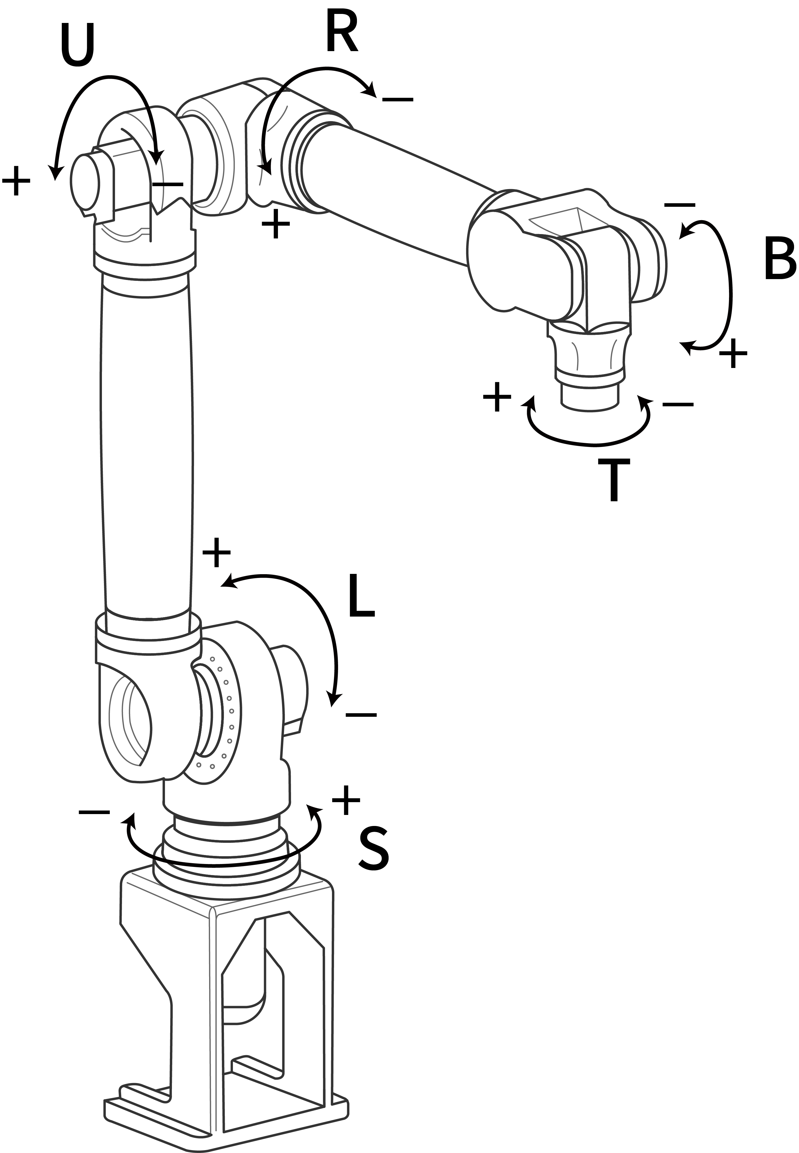
Operates each joint axis of the robot independently. When jogging a single axis in joint coordinates, the corresponding axis value of the robot's joint coordinates will change in the Monitor - Machine Coordinates interface.
Cartesian Coordinate System:
The robot end-effector TCP point moves parallel to the base X, Y, and Z axes. A, B, and C represent rotations around the X, Y, and Z axes respectively. The Euler angle order used in this system is X'Y'Z', and the fixed angle order is ZYX.
Tool Coordinate System:
The tool coordinate system uses the effective direction of the wrist tool as the Z axis, and defines the coordinate system origin at the tool tip TCP point. The robot body TCP point moves parallel according to the coordinates. TA, TB, and TC represent rotations around the TX, TY, and TZ axes respectively.
User Coordinate System:
XYZ Cartesian coordinates are defined at any position. The robot body TCP point moves parallel according to the coordinates.
Joint Coordinate System
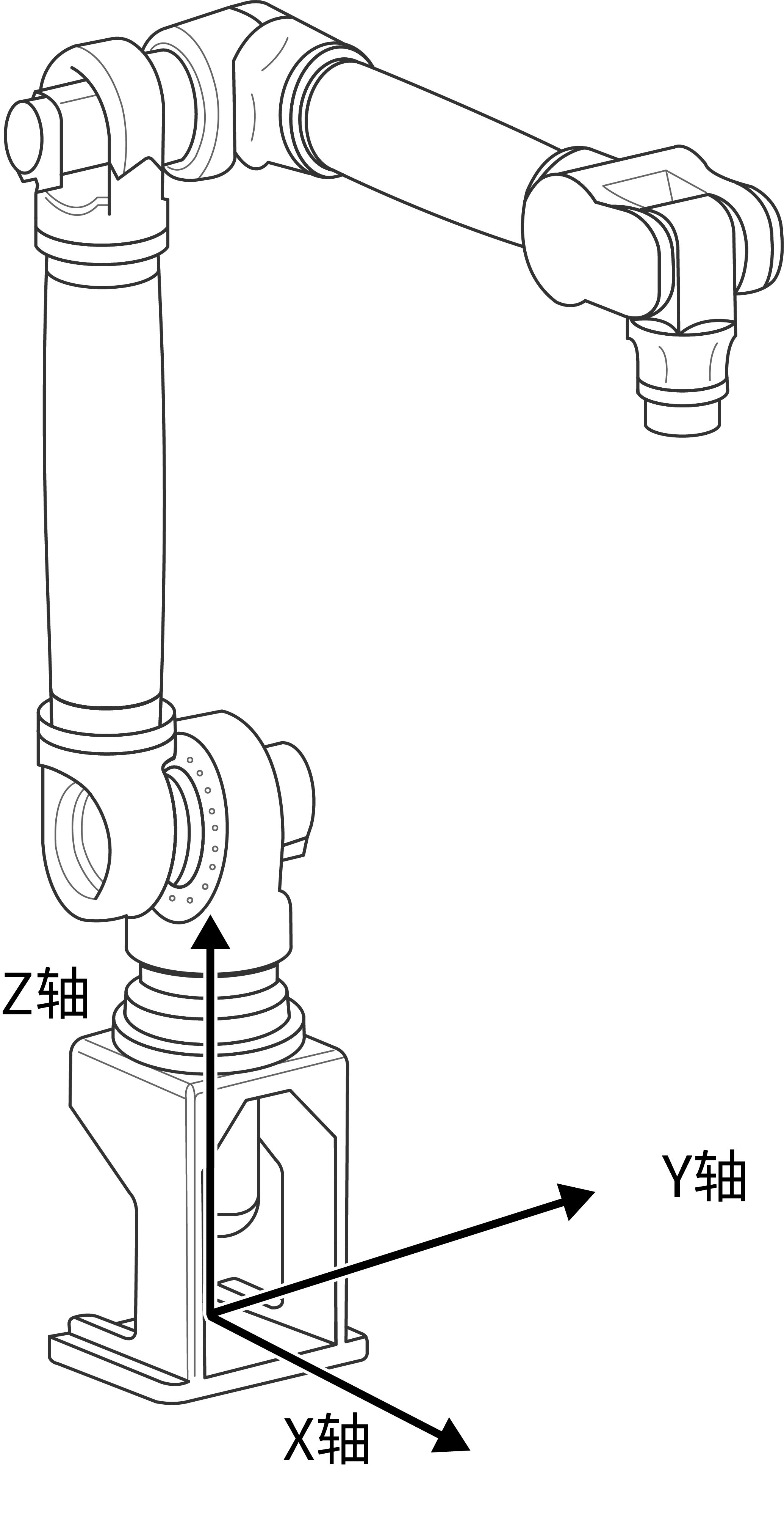
Cartesian Coordinate System
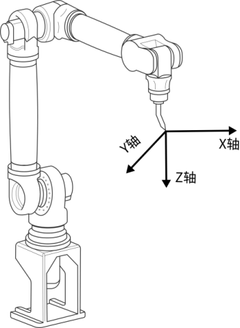
Tool Coordinate System
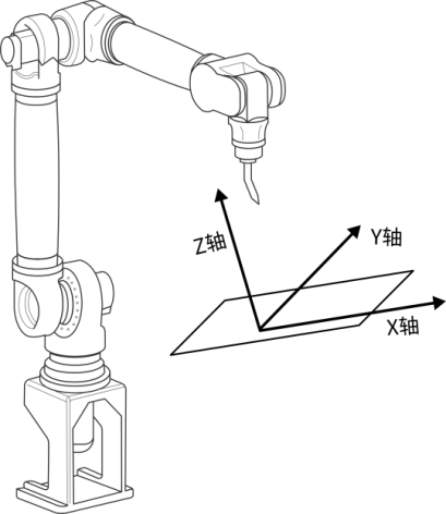
User Coordinate System
Coordinate Systems and Axis Operation
Joint Coordinate System
In the joint coordinate system, each axis of the robot can operate independently.
Axis Operation in Joint Coordinate System
| Axis Name | Axis Operation | Action |
|---|---|---|
| Basic Axes | ||
| S-axis | S+/S- | Rotate body left and right |
| L-axis | L+/L- | Lower arm moves forward and backward |
| U-axis | U+/U- | Upper arm moves up and down |
| Wrist Axes | ||
| R-axis | R+/R- | Wrist rotation |
| B-axis | B+/B- | Wrist moves up and down |
| T-axis | T+/T- | Wrist rotation |
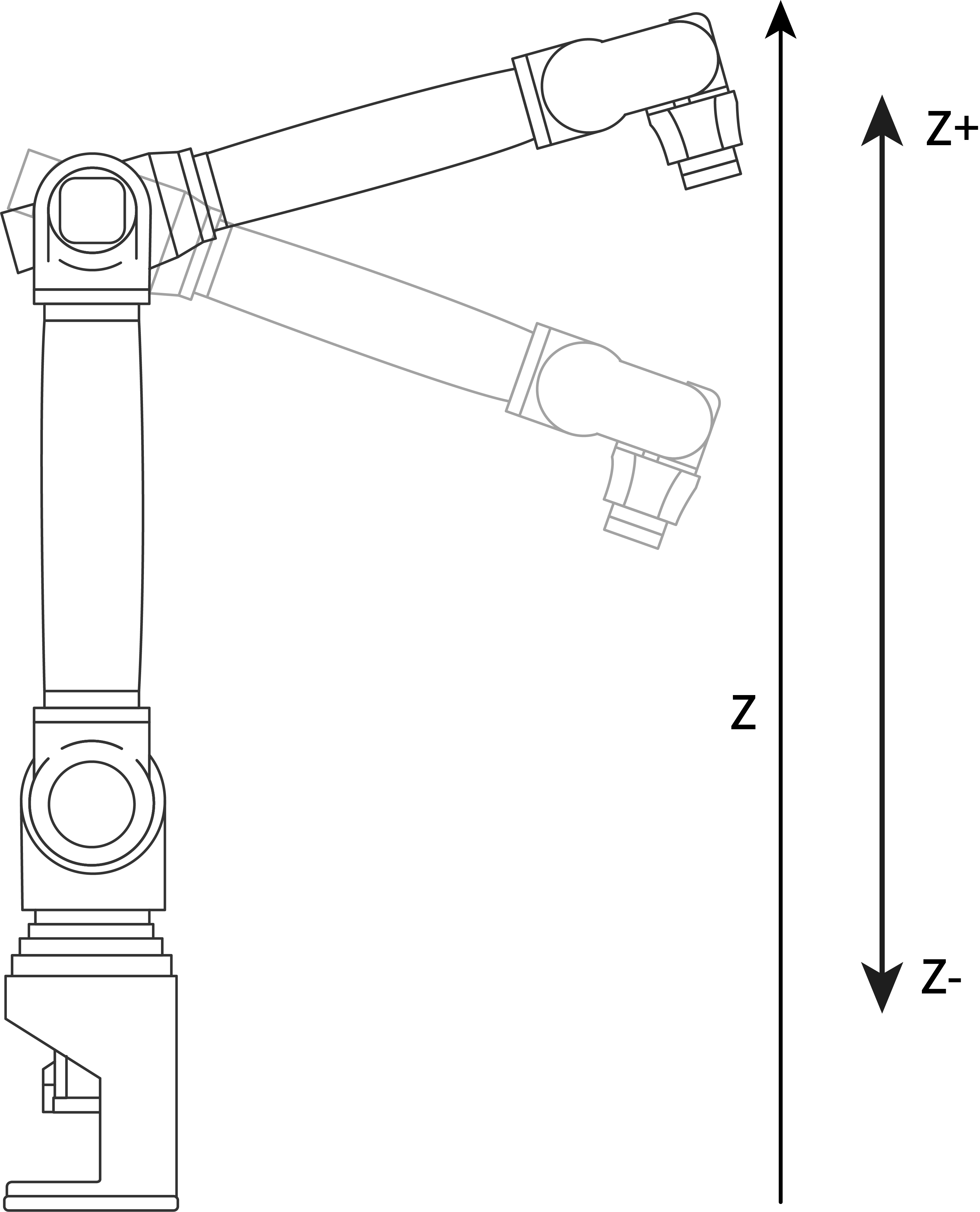
Cartesian Coordinate System
In the Cartesian coordinate system, the robot moves parallel to the body X, Y, and Z axes, as shown in the figure below.
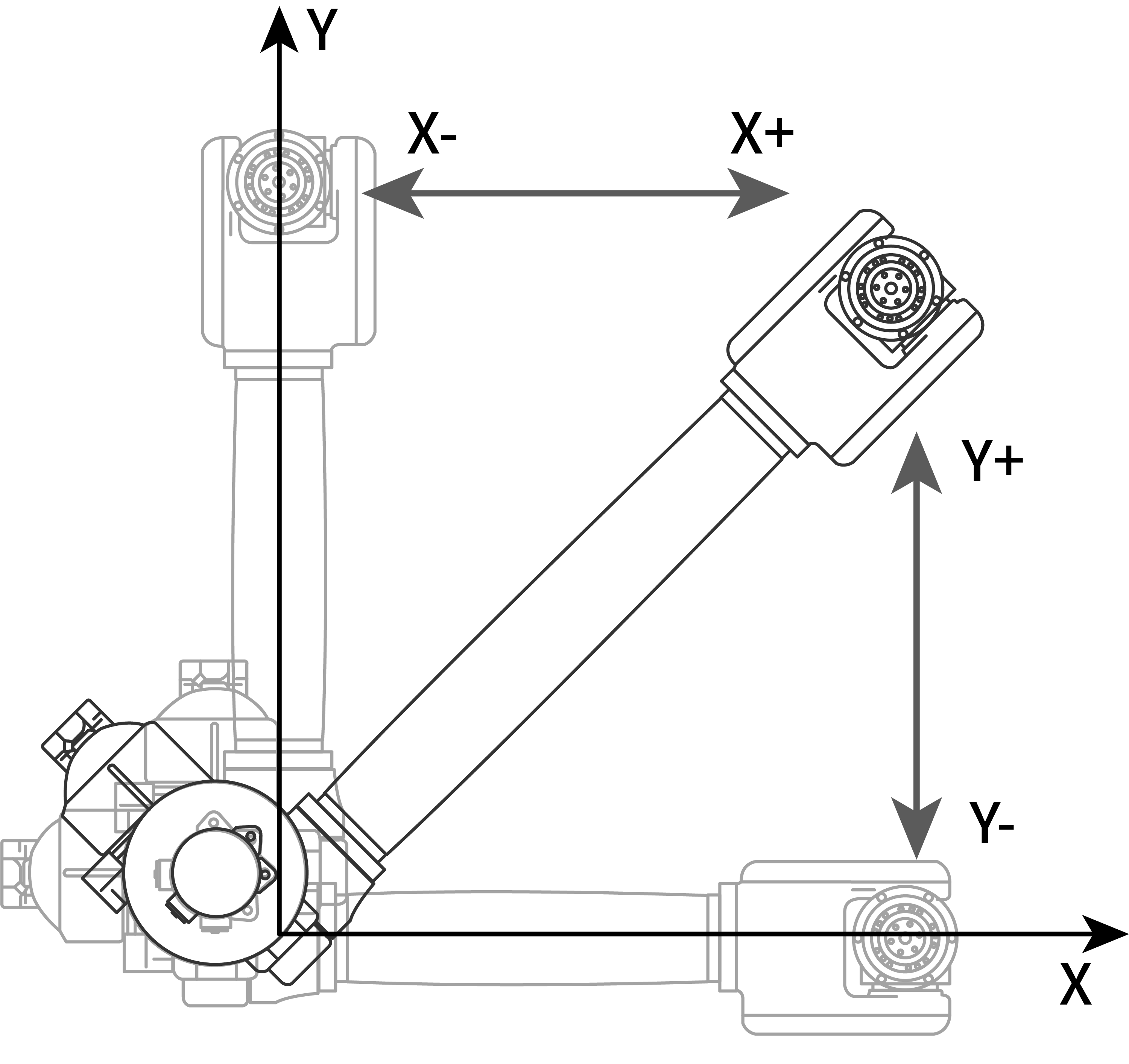
Axis Operation in Cartesian Coordinate System
| Axis Name | Axis Operation | Action |
|---|---|---|
| Basic Axes | ||
| X-axis | X+/X- | Move parallel along X-axis |
| Y-axis | Y+/Y- | Move parallel along Y-axis |
| Z-axis | Z+/Z- | Move parallel along Z-axis |
| Orientation Axes | ||
| A-axis | A+/A- | Rotate around X-axis |
| B-axis | B+/B- | Rotate around Y-axis |
| C-axis | C+/C- | Rotate around Z-axis |
Tool Coordinate System
In the tool coordinate system, the robot moves parallel to the X, Y, and Z axes defined at the tool tip point.
The tool coordinate system uses the effective direction of the tool mounted on the robot wrist flange as the Z axis, and defines the coordinates at the tool tip point. Therefore, the direction of the tool coordinate axes changes with wrist movement, as shown in the figure below.
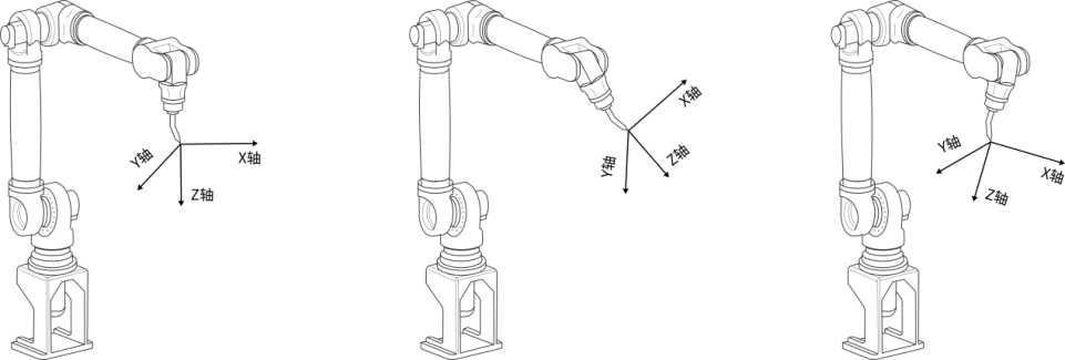
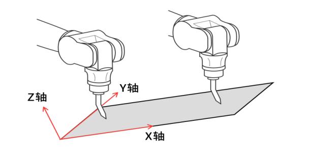
The motion in the tool coordinate system is not affected by changes in the robot's position or posture, and mainly uses the tool's effective direction as the reference for motion.
Therefore, tool coordinate motion is most suitable for applications where the tool posture remains constant relative to the workpiece and moves in parallel translation, as shown in the figure below.
Axis Operation in Tool Coordinate System
| Axis Name | Axis Operation | Action |
|---|---|---|
| Basic Axes | ||
| TX-axis | TX+/TX- | Move parallel along TX-axis |
| TY-axis | TY+/TY- | Move parallel along TY-axis |
| TZ-axis | TZ+/TZ- | Move parallel along TZ-axis |
| Orientation Axes | ||
| TA-axis | TA+/TA- | Rotate around TX-axis |
| TB-axis | TB+/TB- | Rotate around TY-axis |
| TC-axis | TC+/TC- | Rotate around TZ-axis |
User Coordinate System
In the user coordinate system, X, Y, and Z axes at any angle can be set at any position within the robot's motion range. The robot moves parallel to these set axes, as shown in the figure below.
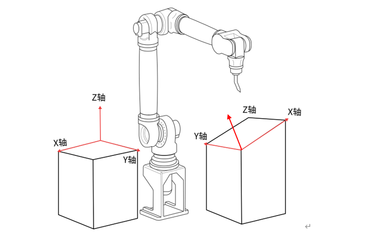
Axis Operation in User Coordinate System
| Axis Name | Axis Operation | Action |
|---|---|---|
| Basic Axes | ||
| UX-axis | UX+/UX- | Move parallel along UX-axis |
| UY-axis | UY+/UY- | Move parallel along UY-axis |
| UZ-axis | UZ+/UZ- | Move parallel along UZ-axis |
| Orientation Axes | ||
| UA-axis | UA+/UA- | Rotate around UX-axis |
| UB-axis | UB+/UB- | Rotate around UY-axis |
| UC-axis | UC+/UC- | Rotate around UZ-axis |
Examples of User Coordinate System Usage
Using user coordinates can make various teaching operations simpler.
The following examples illustrate this.
When there are multiple fixture tables:
Using user coordinates set for each fixture table can make manual operations simpler.
When performing arrangement and stacking operations:
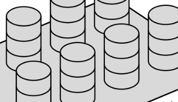
By calibrating the user coordinate system and setting the user coordinates on the pallet, it becomes simpler to set the displacement increment for parallel translation.
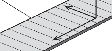
When synchronizing with a conveyor belt: In the conveyor belt process, you need to calibrate the user coordinate system to specify the direction of conveyor belt movement.
External Axes
After switching to external axes using the [External Axis] button, you can perform jog teaching of external axes; external axes only support joint jogging.
| Axis Name | Axis Operation | Action |
|---|---|---|
| O1-axis | O1+/O1- | External axis 1 movement |
| O2-axis | O2+/O2- | External axis 2 movement |
| O3-axis | O3+/O3- | External axis 3 movement |
| O4-axis | O4+/O4- | External axis 4 movement |
| O5-axis | O5+/O5- | External axis 5 movement |
4.2 Coordinate System Description and Switching
This product contains four coordinate systems: joint coordinate system, Cartesian coordinate system, tool coordinate system, and user coordinate system.
In the joint coordinate system, all positions are angle values of the robot's joint axes relative to the mechanical zero point.
The Cartesian coordinate system is also called the "base coordinate system". All positions are coordinate values of the robot tip (flange center) relative to the robot base center (unit: mm).
In the tool coordinate system, all positions are coordinate values of the robot tool tip (TCP point) relative to the robot base center (unit: mm). For its definition and usage, refer to the Tool and User Coordinate chapter.
The user coordinate system is also called the "workpiece coordinate system". All positions are coordinate values of the robot tool tip (or flange center when no tool is mounted) relative to the user coordinate system origin (unit: mm). For its definition and usage, refer to the Tool and User Coordinate chapter.
4.2.1 Teach Mode
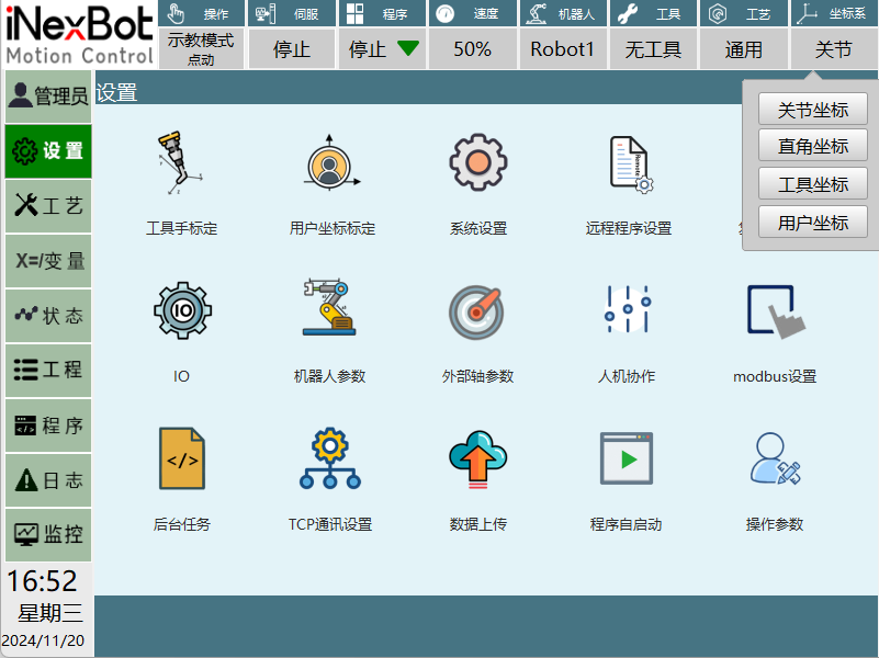
Press the [Coordinate] physical button at the bottom of the teach pendant. Each press switches the coordinate system in the following order. Confirm through the top status bar display, or click the coordinate system field in the status bar to open the coordinate system selection menu and click the corresponding coordinate system to switch: Joint -> Cartesian -> Tool -> User. As shown in the figure below:
5 Tool and User Coordinates
Tool hand calibration and tool coordinate system introduction:
Flange center: The origin of the default tool coordinate system. The +X direction is from the flange center toward the flange locating hole, the +Z direction is perpendicular to the flange outward, and the Y direction is determined by the right-hand rule. New tool coordinate systems are derived from changes relative to the default tool coordinate system.
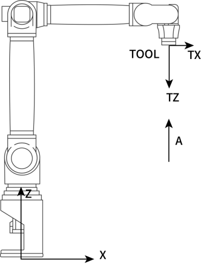
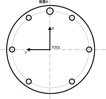
TCP: TOOL CENTER POINT, i.e., the tool center point.
Robot trajectory and speed: Refers to the trajectory and speed of the TCP point.
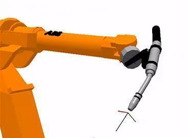
TCP is generally set at the center of the gripper, the tip of the welding wire, the front of the spot welding arm, etc.
To describe the position of an object in space, a coordinate system must be fixed to the object, and then the pose of that coordinate system (origin position and three coordinate axis orientations) must be determined, which requires 7 DOF (degrees of freedom) to fully describe the pose of the rigid body. For industrial robots, a tool (Tool) needs to be mounted on the end flange for operations. To determine the pose of the Tool, a tool coordinate TCS (Tool Coordinate System) is bound to the Tool, and the origin of the TCS is the TCP (Tool Center Point). When programming robot trajectories, the pose of the TCS in other coordinate systems needs to be recorded in the program for execution.
Industrial robots generally have a pre-defined TCP. The XY plane of the TCP is bound to the flange plane of the robot's sixth axis, and the origin of the TCP coincides with the flange center. Obviously, the TCP is at the flange center. ABB robots call the TCP tool0, while REIS robots call it _tnull. Although the default TCP can be used directly, in practical use, such as welding, users typically define the TCP point at the tip of the welding wire (actually the pose of the welding gun tool's coordinate system in the tool0 coordinate system). In this case, the position recorded in the program is the position of the welding wire tip, and the recorded orientation is the orientation of the welding gun rotating around the welding wire tip.
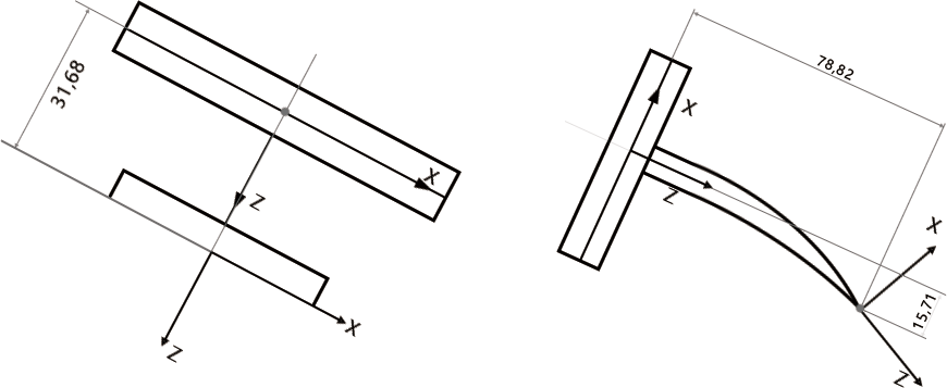
Think about it: We know that the tool coordinate system is a research object in motion, but what role does it play in actual debugging? Consider how the gripper posture and position in Figure 1 and Figure 2 below were adjusted?
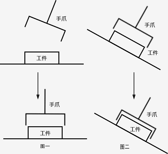
From this thought exercise, two inferences can be drawn:
Inference 1: If the gripper in Figure 1 has a rotation point, the gripper can simply rotate around this rotation point.
Inference 2: If there is a gripper advancement direction in Figure 2, it can simply move directly.
Conclusion: The purpose of establishing a tool coordinate system:
Establish the TCP point (tool center point) of the tool to facilitate adjusting the tool state.
Determine the tool feed direction to facilitate tool position adjustment.
Tool coordinate system characteristics:
A new tool coordinate system is obtained by changing relative to the default tool coordinate system. The position and orientation of the new tool coordinate system always maintain an absolute position and posture relationship with the flange, but they are constantly changing in space.
Tool hand parameter settings:
Click Settings - Tool Hand Calibration to enter the tool hand calibration interface, as shown in the figure below:
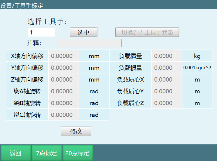
If you have detailed tool parameters, you can directly fill in the tool end-effector offset parameters on this interface without performing seven-point calibration.
When entering this interface, the tool hand size parameters saved in the controller are automatically read (default values are all 0). If you change the tool hand, please refill the parameters.
Detailed parameter setting steps are as follows:
Open the tool hand calibration interface. The following table describes each parameter:
| Parameter | Function |
|---|---|
| X-axis direction offset | Offset length of the tool end relative to the flange center along the Cartesian coordinate system X-axis direction (mm). |
| Y-axis direction offset | Offset length of the tool end relative to the flange center along the Cartesian coordinate system Y-axis direction (mm). |
| Z-axis direction offset | Offset length of the tool end relative to the flange center along the Cartesian coordinate system Z-axis direction (mm). |
| Rotation around A-axis | Rotation angle of the tool end relative to the flange center around the Cartesian coordinate system X-axis direction (deg) |
| Rotation around B-axis | Rotation angle of the tool end relative to the flange center around the Cartesian coordinate system Y-axis direction (deg) |
| Rotation around C-axis | Rotation angle of the tool end relative to the flange center around the Cartesian coordinate system Z-axis direction (deg) |
Click the [Modify] button.
Fill in the corresponding parameters for the tool, where each parameter's function is as shown in the table above;
After confirming correctness, click the [Save] button. Setup is successful.
WARNING

Please align the flange parallel to the horizontal plane before collecting data!
Click the [Clear] button to reset the filled parameters to zero.
If during the parameter setting process you click the [Return] or [Seven-Point Calibration] button at the bottom operation area, the interface will jump accordingly, and unsaved setting parameters will not be retained.
5.1 Seven-Point Calibration
Click the [Seven-Point Calibration] button at the bottom to enter the seven-point calibration interface, as shown:
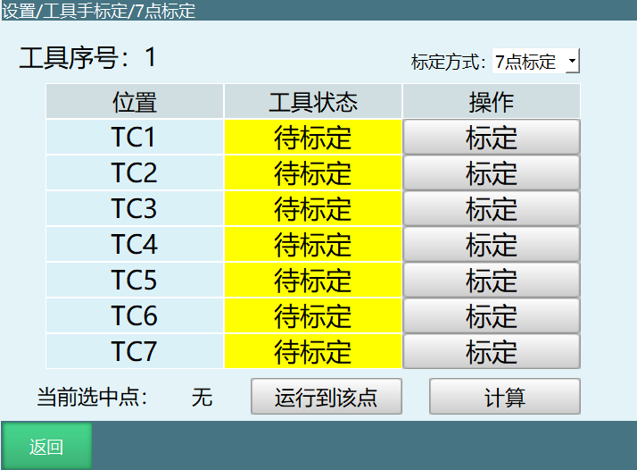
If you do not have detailed tool parameters, you can perform TCP calibration to automatically calculate the tool's various size parameters. The specific calibration steps are as follows:
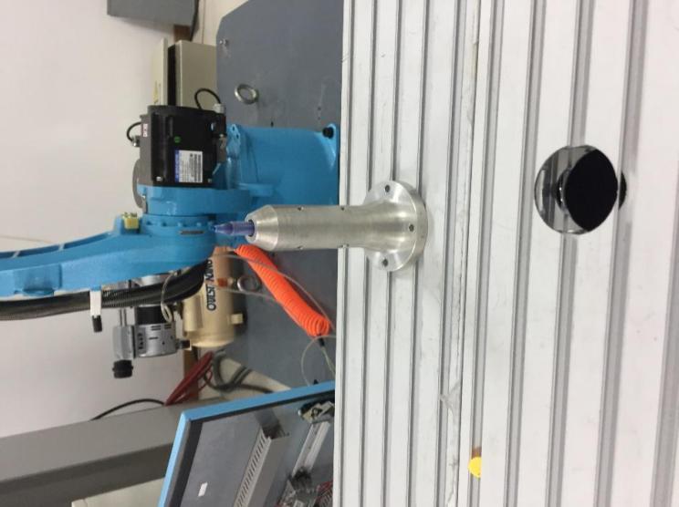
Use a pen tip as the reference point and ensure this reference point is fixed, as shown in the figure below:
Align the tool end vertically and directly at the reference point, click the [Calibrate] button corresponding to "TC1" on the interface, as shown below:
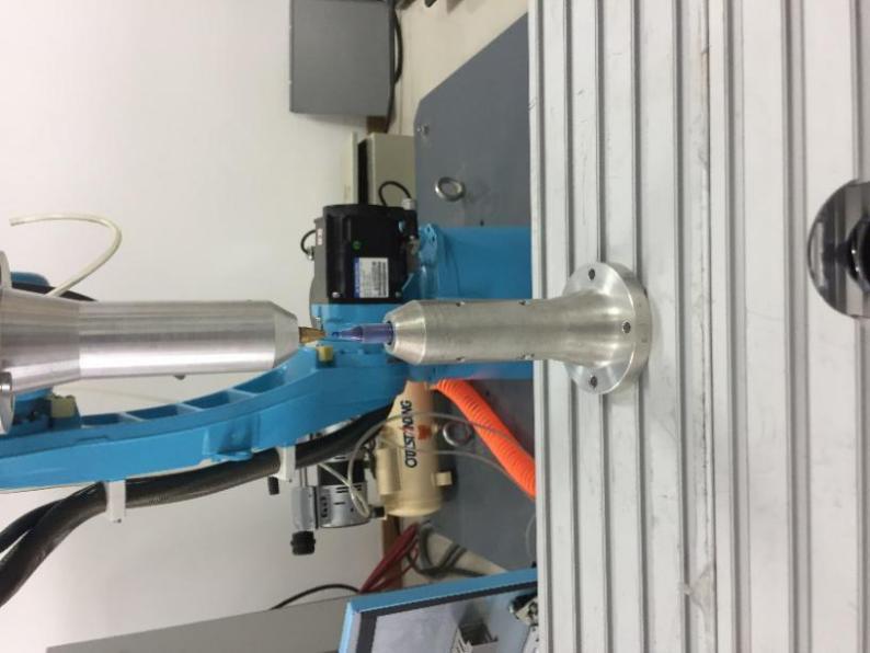
TC2 Calibration: Switch the robot to a different posture, align the end directly at the reference point, click the [Calibrate] button corresponding to this row, as shown below:
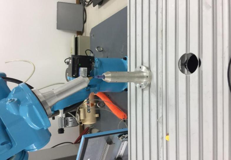
TC3 Calibration: Switch the robot to a different posture, align the end directly at the reference point, click the [Calibrate] button corresponding to this row, as shown below:
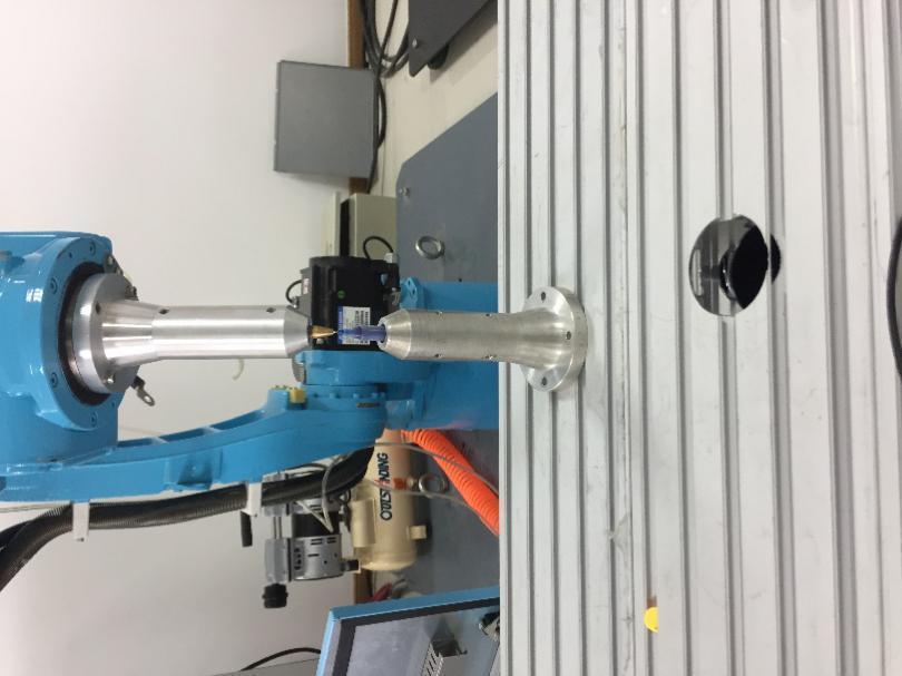
TC4 Calibration: Switch the robot to a different posture, align the end directly at the reference point, click the [Calibrate] button corresponding to this row, as shown below:
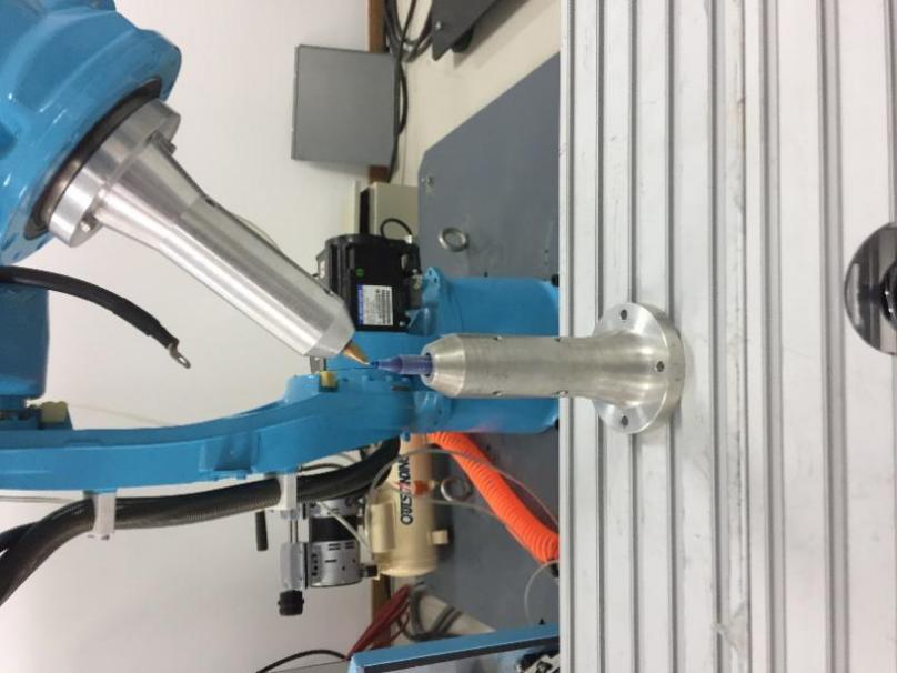
TC5 Calibration: Align the tool end vertically and directly at the reference point (same as TC1), click the [Calibrate] button corresponding to this row, as shown below:
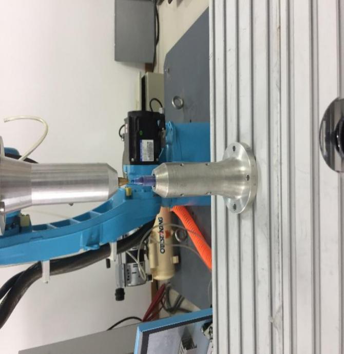
TC6 Calibration: Based on TC5, move any distance in the negative X-axis direction of the Cartesian coordinate system, click the [Calibrate] button corresponding to this row, as shown below:
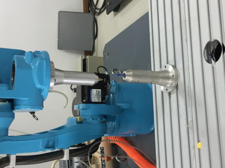
TC7 Calibration: Based on TC6, move any distance in the positive Y-axis direction of the Cartesian coordinate system, click the [Calibrate] button corresponding to this row, as shown below:
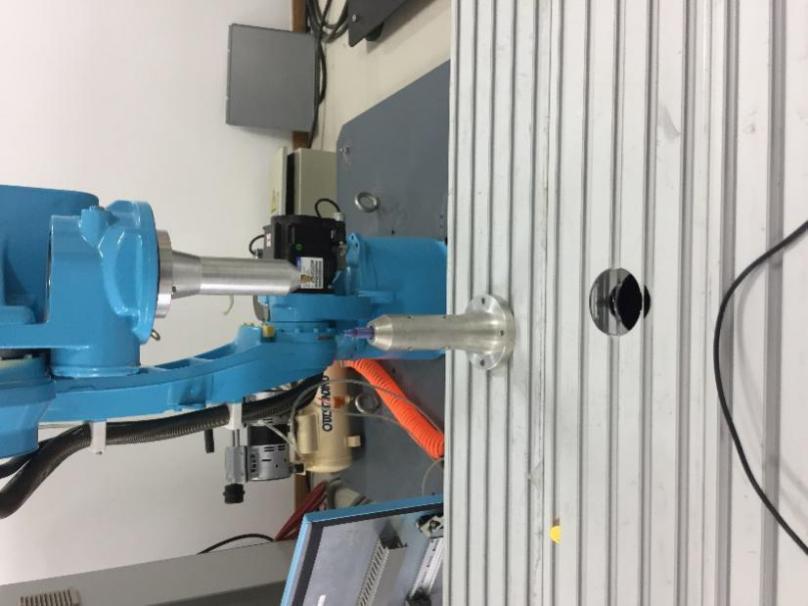
Click [Move to this point] to verify if the calibration is accurate;
Click the [Calculate] button. Calibration is successful.
If unsatisfied with a calibration point during the process, click the [Cancel Calibration] button corresponding to that row. After canceling, recalibrate the point.
Click the [Demo] button at the bottom to open the "Demo" interface explaining how to perform tool calibration.
Click the [Return] button at the bottom to return to the "Tool Hand Calibration" interface.
5.2 Six-Point Calibration
Enter Settings - Tool Hand Calibration - 7-Point Calibration interface, and the calibration method can be changed to 6-point calibration. As shown:
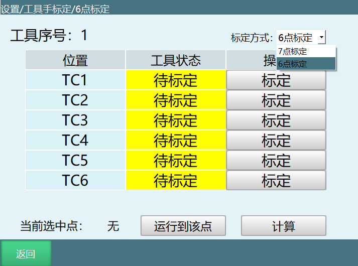
Calibration method:
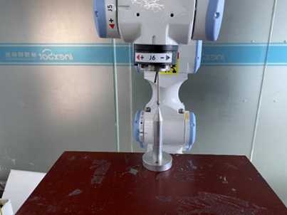
First point: Robot axis 5 is vertically downward, as shown below:
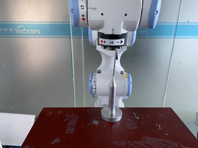
Second point: Based on the first point, the C-axis rotates 180 degrees, as shown:
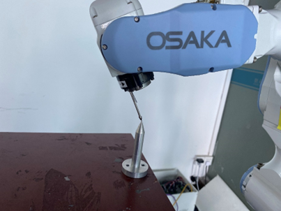
Third point: Based on the first point, the B-axis angle is at 35 degrees;
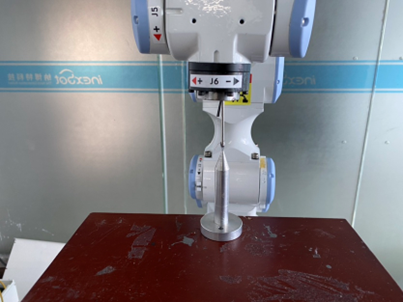
Fourth point: The robot returns to zero, then the tool hand tip is vertical;
Fifth point: Based on the fourth point, move X-;
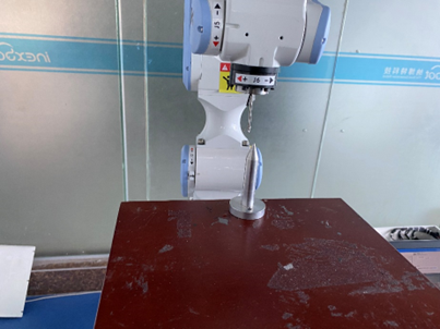
Sixth point: Based on the fifth point, move Y+;
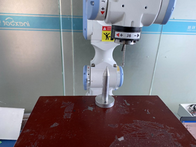
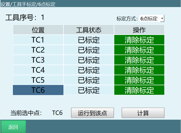
After 6-point calibration is complete, select any calibration point, click [Move to this point] to verify if the calibration is accurate;
Click the [Calculate] button. Calibration is successful. Click the [Return] button at the bottom to return to the "Tool Hand Calibration" interface. Rotating around ABC can verify the calibration error;
If unsatisfied with a calibration point during the process, click the [Cancel Calibration] button corresponding to that row. After canceling, recalibrate the point;
Click the [Return] button at the bottom to return to the "Tool Hand Calibration" interface.
5.3 12/15-Point Calibration
The 12-point/15-point/20-point calibration share the same calibration interface. Calibrating the first 15 points uses the 15-point calibration method.
12-point calibration means the 15-point calibration without the last three points (13-15). The calibration result only contains the tool hand XYZ axis direction offsets, without rotation values around ABC.
Click the [20-Point Calibration] button at the bottom of the "Tool Hand Calibration" interface to enter the calibration interface, as shown:
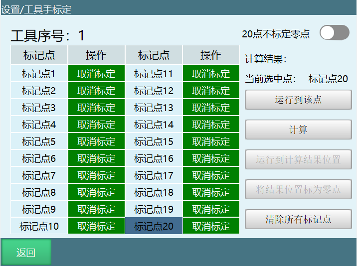
Find a reference point (the tip of the calibration cone is the reference point) and ensure this reference point is fixed.
Start inserting position points. For each point inserted, click [Mark this point]. Insert fifteen points.
The specific steps are as follows:
First point: The robot returns to zero. Through Cartesian coordinates, align the robot tip with the calibration cone tip, calibrate the first point;
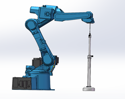
Second point: Based on the first point, rotate C 180 degrees through the Cartesian coordinate system; align the tip and calibrate the second point;
Third point: The robot returns to zero. Through the Cartesian coordinate system, align the robot tip with the calibration cone tip; calibrate the third point (same as the first point);
Fourth point: Based on the third point, perform B- through the Cartesian coordinate system, with the degree between 30-60 degrees. Align the tip and calibrate the fourth point;
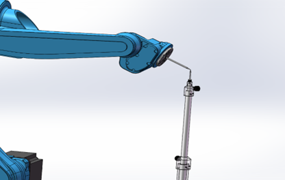
Fifth point: Based on the fourth point, perform B+ through the Cartesian coordinate system, J5>-90 degrees. Align the robot tip with the calibration cone tip, calibrate the fifth point;
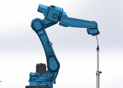
Sixth point: Select the first point and move the robot to the first point. Based on the first point, perform B+ through the Cartesian coordinate system, J5>-90 degrees. Align the tip and calibrate the sixth point;
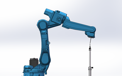
Seventh point: Based on the first point, perform B- through the Cartesian coordinate system, J5>-90 degrees. Align the tip and calibrate the seventh point;
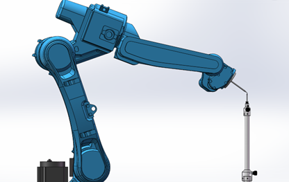
Eighth point: Based on the seventh point, perform A+ through the Cartesian coordinate system, rotate 90 degrees, J5>-90 degrees. Align the tip and calibrate the eighth point;
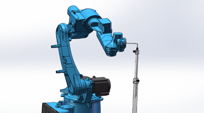
Ninth point: Based on the seventh point, perform A- through the Cartesian coordinate system, rotate 90 degrees, J5>-90 degrees. Align the tip and calibrate the ninth point;
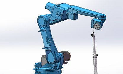
Tenth point: The robot returns to the first point. Through joint coordinate system, jog axis 5 upward, J5<-90 degrees. Align the tip and calibrate the tenth point;
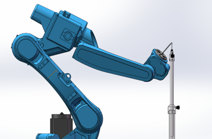
Eleventh point: Based on the tenth point, perform A+ through the Cartesian coordinate system, rotate 90 degrees, J5<-90 degrees. Align the tip and calibrate the eleventh point;
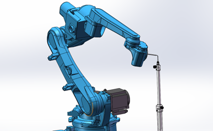
Twelfth point: Based on the tenth point, perform A- through the Cartesian coordinate system, rotate 90 degrees, J5<-90 degrees. Align the tip and calibrate the twelfth point;
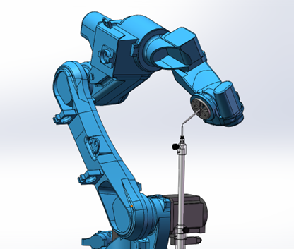
Thirteenth point: The robot returns to zero position. Adjust the robot posture so that the robot end tool tip points vertically downward. Align the calibration tip with the calibration cone, calibrate the thirteenth point;
Fourteenth point: Based on the thirteenth point, perform X- through the Cartesian coordinate system. The robot displaces a distance, directly click to calibrate the fourteenth point;
Fifteenth point: Based on the fourteenth point, perform Y+ through the Cartesian coordinate system. The robot displaces a distance, directly click to calibrate the fifteenth point;
After marking is complete, click [Calculate].
Button descriptions:
[Cancel Calibration]: If unsatisfied with a calibration point during the process, click the [Cancel Calibration] button corresponding to that row. After canceling, recalibrate the point.
[Move to this point]: After calibrating each point, click [Move to this point] and the robot will move to that point.
[Mark result position as zero]: Set the calibrated compensated position as the current robot zero position.
[Clear all marked points]: Calibration points are saved to the controller. The calibration results are only cleared when clicking Cancel Calibration, Clear All Marked Points, or switching the tool hand into the calibration interface.
Note
For each point's posture, please try to use multiple orientations. If the postures taken are all in a fixed direction, it may lead to reduced accuracy.
During the calibration process, please keep the reference point fixed, otherwise calibration error will increase.
Click the [Return] button at the bottom to return to the "Tool Hand Calibration" interface.
5.4 20-Point Calibration
The 12-point/15-point/20-point calibration share the same calibration interface. Calibrating all 20 points uses the 20-point calibration method.
Click the [Twenty-Point Calibration] button at the bottom of the "Tool Hand Calibration" interface to enter the "Twenty-Point Calibration" interface, as shown:
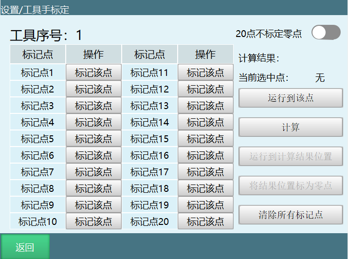
Find a reference point (pen tip as reference point) and ensure this reference point is fixed.
Start inserting position points. For each point inserted, click [Mark this point]. Insert 20 points. The greater the posture difference between each point, the better.
Manufacturer recommendation: For the calibration steps, the first point has the tool hand posture vertically downward, the second point moves A+, the third point moves A+, the fourth point moves A+, the fifth point moves A-, the sixth point moves A-, the seventh point moves A-, the eighth point moves B+, the ninth point moves B+, the tenth point moves B+, the eleventh point moves B-, the twelfth point moves B-, the thirteenth point moves B-, and the remaining points mainly move the C-axis in a star pattern for calibration.
Specific calibration steps are as follows:
First point: Robot tool hand end vertical to reference point
Second point: Based on the first point, move A+
Third point: Based on the first point, move A+ 40 degrees
Fourth point: Based on the first point, move A+ 60 degrees
Fifth point: Based on the first point, move A- 20 degrees
Sixth point: Based on the first point, move A- 40 degrees
Seventh point: Based on the first point, move A- 60 degrees
Eighth point: Based on the first point, move B+ 20 degrees
Ninth point: Based on the first point, move B+ 30 degrees
Tenth point: Based on the first point, move B+ 40 degrees
Eleventh point: Based on the first point, move B- 20 degrees
Twelfth point: Based on the first point, move B- 30 degrees
Thirteenth point: Based on the first point, move B- 40 degrees
Fourteenth point: Based on the first point, move C+ 30 degrees
Fifteenth point: Based on the first point, move C+ 50 degrees
Sixteenth point: Based on the first point, move C+ 70 degrees
Seventeenth point: Based on the first point, move C+ 90 degrees
Eighteenth point: Based on the first point, move C- 30 degrees
Nineteenth point: Based on the first point, move C- 60 degrees
Twentieth point: Based on the first point, move C- 90 degrees
After completing the 20-point marking, click [Calculate].
[Cancel Calibration]: If unsatisfied with a calibration point during the process, click the [Cancel Calibration] button corresponding to that row. After canceling, recalibrate the point.
[Move to this point]: After calibrating each point, click [Move to this point] and the robot will move to that point.
[Mark result position as zero]: Set the calibrated compensated position as the current robot zero position.
[Clear all calibration points]: Calibration points are saved to the controller. The calibration results are only cleared when clicking Cancel Calibration, Clear All Calibration Points, or switching the tool hand into the calibration interface.
[20-point without zero calibration] When this option is turned on, only size + posture are calibrated; Move to result position is always grayed out, and [Mark result position as zero] becomes [Save Calculation Result]. In this case, the calibration method is: the first point has the tool hand vertical to the calibration rod, the last two points are calibrated as X- and Y+, and other points are calibrated according to the original 20-point calibration method. When this button is turned off, the 20-point marking method follows the original 20-point calibration method, and the result position can be marked as zero.
Note
For each point's posture, please try to use any orientation. If the postures are rotated in a certain direction, the accuracy may sometimes be inaccurate.
During the calibration process, please keep the reference point fixed, otherwise calibration error will increase.
5.5 User Coordinate System Function
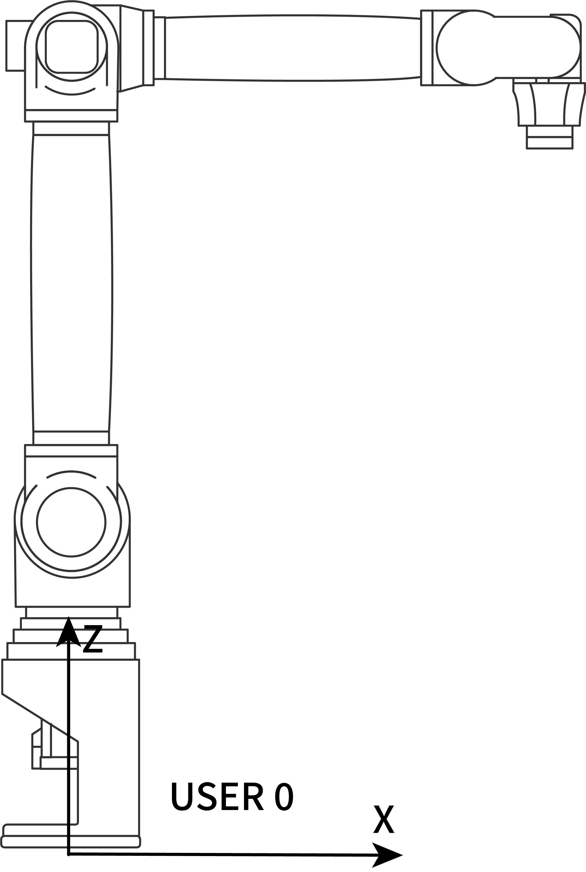
Definition: Default user coordinate system: The default user coordinate system User0 coincides with the Cartesian coordinate system. New user coordinate systems are obtained by changes based on the default user coordinate system.
Think about it: From Thought 1, we know that the user coordinate system is a reference object in motion, but what role does it play in actual debugging?
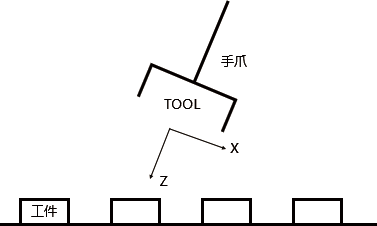
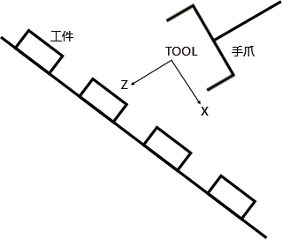
Inference: From the figures, we can see that using the default user coordinate system User 0 or the Cartesian coordinate system would make it very difficult to debug each workpiece position. But if there is a coordinate system whose two directions happen to be parallel to the worktable surface, it would be much more convenient.
User coordinate system function
Determine the reference coordinate system;
Determine the motion direction on the worktable to facilitate debugging.
User coordinate system characteristics
New user coordinate systems are derived from changes based on the default user coordinate system User 0. The position and orientation of the new user coordinate system do not change relative to space.
User coordinate parameter settings
Click the [User Coordinate Calibration] button in the "Settings" interface to enter the "User Coordinate" interface, as shown:
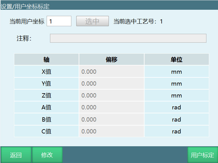
User coordinate parameters are as follows:
| Parameter | Function |
|---|---|
| X value | Offset of user coordinate origin relative to robot base origin in X-axis direction |
| Y value | Offset of user coordinate origin relative to robot base origin in Y-axis direction |
| Z value | Offset of user coordinate origin relative to robot base origin in Z-axis direction |
| A value | Rotation angle (radians) of user coordinate system relative to Cartesian coordinate system around X-axis direction |
| B value | Rotation angle (radians) of user coordinate system relative to Cartesian coordinate system around Y-axis direction |
| C value | Rotation angle (radians) of user coordinate system relative to Cartesian coordinate system around Z-axis direction |
If you have precise values, please fill them in directly. Note that the ABC values are in radians.
User coordinate system calibration:
Click the [User Calibration] button at the bottom of the "User Coordinate Calibration" interface to enter the "User Calibration" interface, as shown.
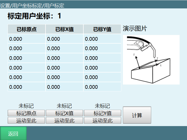
User coordinate system calibration should follow these steps:
Move the robot tip to the desired position as the user coordinate system origin, click the "Calibrate Origin" button;
Move the robot relative to the user coordinate system origin in the desired positive X-axis direction by any distance, click the "Calibrate X-Axis" button;
Move the robot relative to the user coordinate system origin in the desired positive Y-axis direction by any distance, click the "Calibrate Y-Axis" button.
Note
If the user coordinate system Y-axis is not calibrated accurately, the system will automatically compensate.
Click the [Return] button at the bottom of the interface to return to the user coordinate calibration interface.
6 Numeric Variables
This chapter mainly describes the variables of this control system.
| Type | Count | Example |
|---|---|---|
| Global Numeric Variables | ||
| Global Integer | GINT | 999 |
| Global Real | GDOUBLE | |
| Global Boolean | GBOOL | |
| Global String | GSTRING | |
| Local Numeric Variables | ||
| Local Integer | INT | 999 |
| Local Real | DOUBLE | |
| Local Boolean | BOOL | |
| Local String | STRING |
6.1 Global Numeric Variables
Global numeric variables can be used across all robots and all programs. For example, Robot 1's program AA and Robot 2's program BB can simultaneously use the same global numeric variable. This section mainly describes the usage of the global variable interface and the methods for using position and numeric variables.
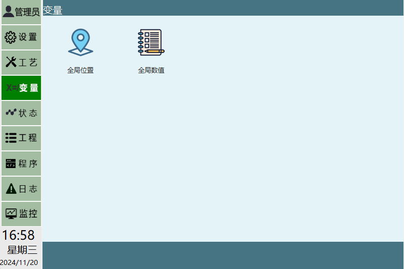
Completing a robot task requires many instructions. If we had to insert instructions and set variables each time, it would be extremely tedious. For this reason, we added numeric variables for easy invocation.
For example, instructions like "WHILE(INT I001=10)...END(WHILE)" are commonly found in programs for completing a certain task. We directly invoke the pre-set numeric variables.
At the same time, global numeric variables can be used to pass information between the main program, called subroutines, and background programs for logical judgment.
Numeric variables store values and include four types: integer variables, real variables, boolean variables, and string variables.
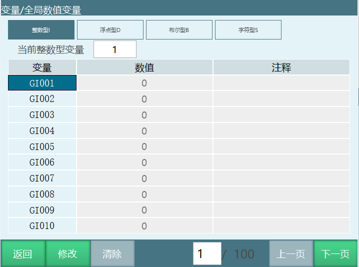
Note: Global variables are saved directly to parameters after being assigned.
6.1.1 Global Boolean Variable GBOOL
Global boolean variables store bytes. On this interface, you can modify each variable's value and comment. The parameters are as follows:
Variable name is the variable's number. Global boolean variable names are GBxxx.
Value is the variable's value. Boolean variable values range from "0/1".
Comment is the user-defined comment for the variable to help identify its function. The range is any value and can be in Chinese.
6.1.2 Global Integer Variable GINT
Global integer variables store integers. On this interface, you can modify each variable's value and comment. The parameters are as follows:
Variable name is the variable's number. Global integer variable names are GIxxx.
Value is the variable's value. Integer variable values are integers.
Comment is the user-defined comment for the variable to help identify its function. The range is any value and can be in Chinese.
6.1.3 Global Floating-Point Variable GDOUBLE
Global real variables store real numbers. On this interface, you can modify each variable's value, content, and comment. The parameters are as follows:
Variable name is the variable's number. Global real variable names are GDxxx.
Value is the variable's value. Floating-point variable values are real numbers.
Comment is the user-defined comment for the variable to help identify its function. The range is any value and can be in Chinese.
Click the data type you want to modify, then select the variable name, click [Modify] to change the value and comment, then click [Save]. Click [Clear] to clear the selected data.
6.1.4 Global String Variable GSTRING
Global string variables can store all variable types and non-variable types, such as: numbers, symbols, letters (including uppercase and lowercase), and Chinese characters.
Variable name is the variable's number. Global string variable names are GSxxx.
Value is the variable's value. String variable range includes all variable types and non-variable types.
6.1.5 Defining Global Numeric Variables
Before using variables, please define them. The method to define variables is as follows:
Click Variables - Global Numeric to enter the global numeric variable interface;
Click global numeric variable;
Select the corresponding variable number, click the "Modify" button;
Fill in the required value in the value and comment fields;
Variables that have not been manually defined default to 0.
6.1.6 Direct Variable Assignment
Using assignment instructions SET GB001, SET GD001, SET GS001, you can directly change variable values during program execution.
In the program, click the "Insert" button;
Select "Variable Class";
To change a global BOOL variable, select the SET GB001 instruction, click OK;
At the variable type, select "GBOOL"; at the variable name, select a previously defined global BOOL variable; at the variable value source, select "Custom"; in the new parameter field, fill in the desired value. For example, if you need to change the variable value to 1, enter 1 here.
For example, to change the GB001 variable value to 1 during program execution, you can insert the instruction GB001=1.
6.1.7 Using Global Numeric Variables for Counting
During program execution, all calculation and assignment operations modify values in the buffer and do not modify values in the "Variable - Global Numeric" interface. To count a certain loop process (such as an inner WHILE loop), you can use the SET instruction.
Use case:
Between WHILE and ENDWHILE instructions is one process. Inside there is an ADD GI001 1 instruction, meaning each time the program loops between WHILE and ENDWHILE, the GI001 variable value increases by one, i.e., the process execution count increases by one. After the program stops running, GI001's value resets to 0, and the process execution count cannot be viewed.
Solution: Insert a SET GI001 instruction after the ADD GI001 1 instruction. When the program finishes running, enter the "Variable - Global Numeric" interface to see that GI001's value represents the process execution count.
Insert method:
Click the [Insert] button in the "Program" interface;
Select "Variable Class" - "SET", click "OK";
Select the variable type. To change a global integer variable, select GINT, and select "GI001" as the variable name;
Click the [Insert] button to complete.
6.1.8 Local Numeric Variables
Local numeric variables can only be used in the program where they are defined. For example, Program A's variables cannot be used in Program B.
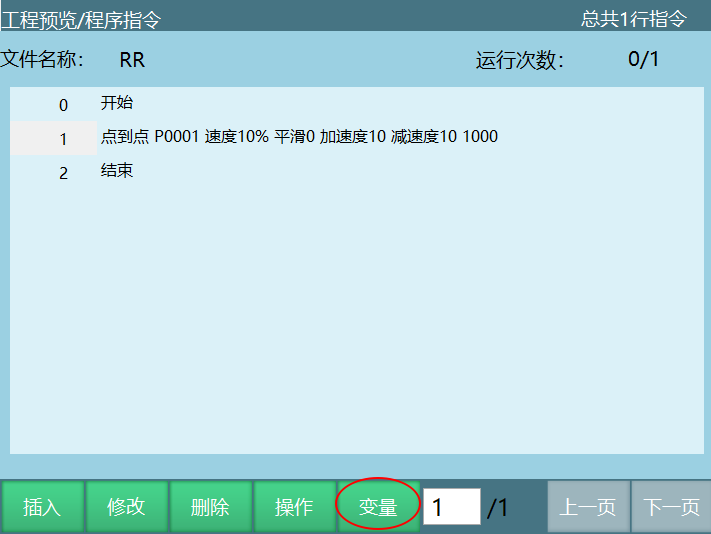
Numeric variables store values and include four types: integer variables, real variables, boolean variables, and string variables.
All defined local numeric variables can only be used in the current program. Other programs and background programs cannot use them.
Local Variable Usage
Defining Local Numeric Variables
Defining local variables differs from defining global variables. Local variables need to be defined by clicking the [Variable] page in the program interface.
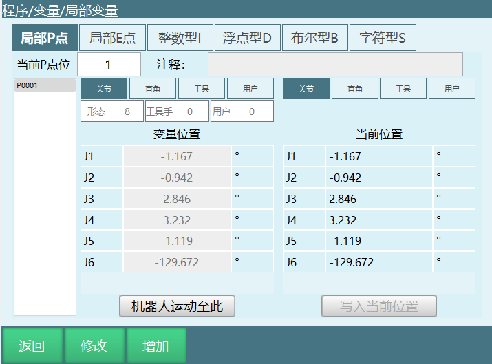
Integer INT
Local integer variables used to store integer values. Variable name is Ixxx.
Default is 0. Select the variable name to modify, click Modify, enter the value, and click Save.
Floating-Point DOUBLE
Local real variables used to store real values. Variable name is Dxxx.
Default is 0. Select the variable name to modify, click Modify, enter the value, and click Save.
Boolean BOOL
Local boolean variables used to store boolean values. Variable name is Bxxx.
Default is 0. Select the variable name to modify, click Modify, enter the value, and click Save.
String STRING
Local string variables can store all variable types and non-variable types, such as: numbers, symbols, letters (including uppercase and lowercase), and Chinese characters.
Local string variables used to store string values. Variable name is Sxxx.
Value is the variable's value. String variable range includes all variable types and non-variable types.
Using calculation instructions to assign local variables
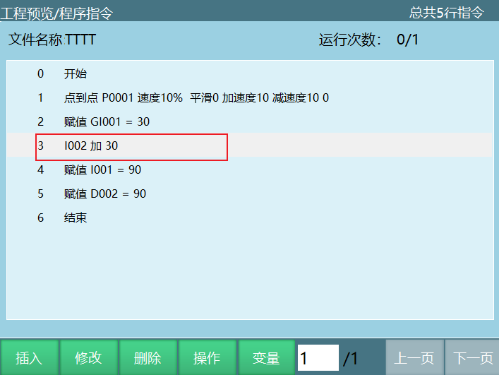
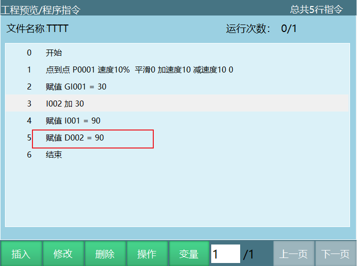
Using ADD, SUB, MUL, DIV, MOD instructions to calculate and assign local variables is the same as calculating global variables. For example, I003 plus 20, as shown in the figure:
Direct assignment to local variables
Using SET I001, SET D001, SET B001 instructions to directly assign local variables is the same as directly assigning global variables. For example: D002=90, as shown in the figure:
7 Position Variables
This chapter mainly describes the variable settings of this control system.
| Type | Count | Example |
|---|---|---|
| Global Position Variables | ||
| Global GP Point | 9999 | GP0001......GP9999 |
| Global GE Point | 9999 | GE0001......GE9999 |
| Local Position Variables | ||
| Local P Point | 9999 | P0001.........P9999 |
| Local E Point | 9999 | E0001.........E9999 |
7.1 Global Position Variables
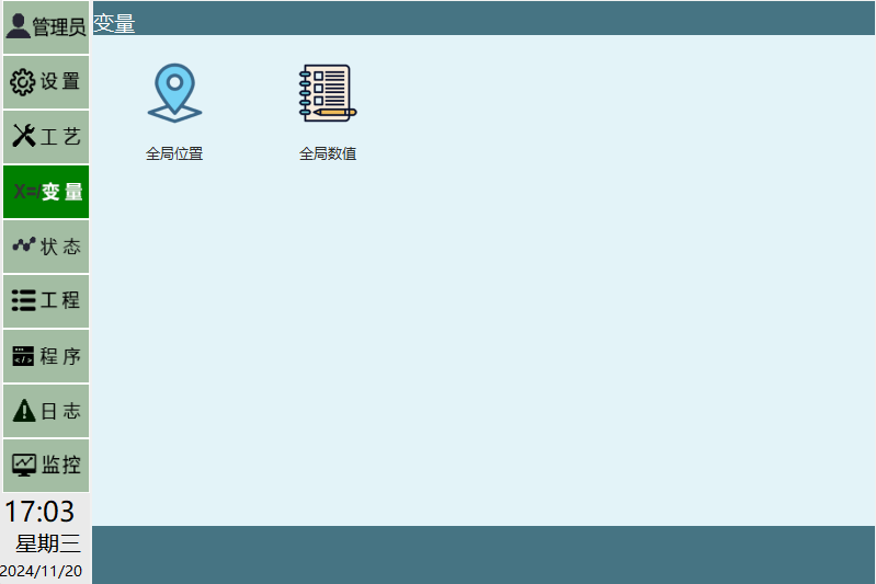
Global GP points can be used across all job files of one robot. Defining global position variables requires the "Variable - Global Position" interface.
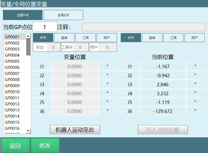
Global position variable definition method:
Enter the "Variable" - "Global Position" interface;
Select the variable to define, e.g., GP0001;
Teach the robot to the desired position, and switch to the desired coordinate system, e.g., Cartesian coordinate system;
Click the [Modify] button;
Click the [Record Current Point] button;
Click the [Save] button.
7.2 Local Position Variables
Local position variables (P000X) can only be used in a single job file and cannot be shared across all job files.
Local position variables can only be defined when inserting MOVJ, MOVL, MOVC, and other motion instructions, in the program instruction interface - Variable section.
Local Position Variable Setting Method 1
- Click Program - Variable - Local Variable to enter the local variable view interface;
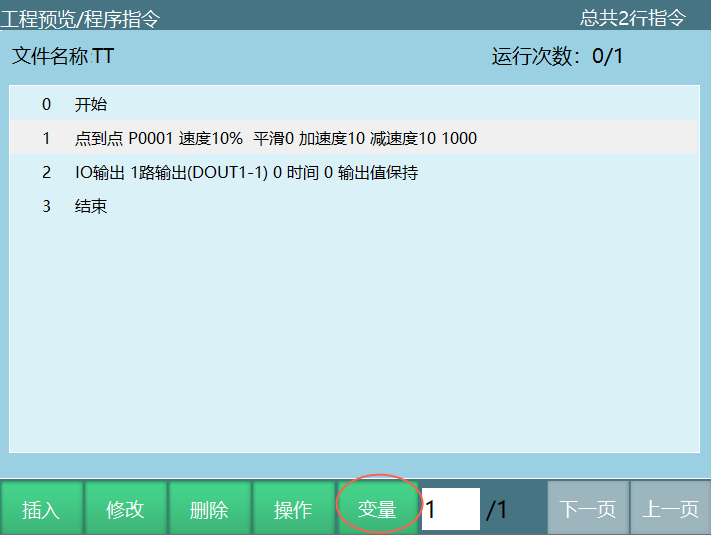
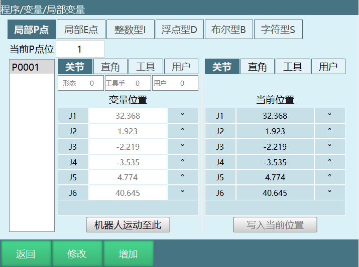
- You can perform functions such as modifying point positions, adding point positions, moving to the point, and writing current position on local position variables.
Local Position Variable Setting Method 2
Create or modify a MOVJ instruction, enter the instruction interface;
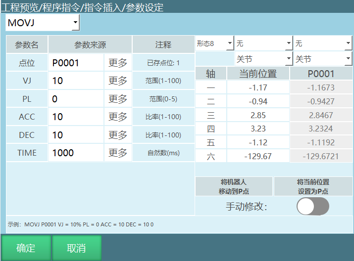
The Current Position column shows the robot position in the currently selected coordinate system; The P0001 column shows the robot position in the selected coordinate system for the P point;
Move the robot to the P point (requires teach mode power-on jog operation);
Set the current position as the P point. Click to save the current point to the local P point;
Manual modification: Open to manually enter P point coordinates.
7.3 Position Variable Parameters
Configuration Parameters
Configuration parameters are only available for six-axis serial multi-joint robots.
The configuration value is a binary conversion value of the robot's 1st, 3rd, and 5th axis positions.
Conversion Method
For example, a six-axis robot has axis 1 at 59 degrees, axis 2 at 69 degrees, axis 3 at 79 degrees, axis 4 at 89 degrees, axis 5 at 99 degrees, axis 6 at 109 degrees;
Take axes 1/3/5 from these. If the position range is between -90 and +90, the value is 1; otherwise, it is 0;
So the result is:
| Axis 1 | Axis 3 | Axis 5 |
|---|---|---|
| Binary value |
Binary 110 = decimal 6;
The configuration value is the decimal result plus 1, so this point's configuration value is 7.
When selecting "Current", the robot will automatically calculate which configuration the current point belongs to. The configuration value corresponds to which range the robot's 1/3/5 axes are in. For example: Configuration 3 = 010 (axis 1, axis 3, axis 5) + 1 = 011. Axis 1 is not within -90 to 90 degrees, axis 3 is within the range, and axis 5 is not within the range.
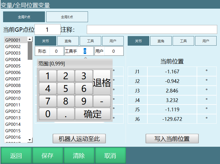
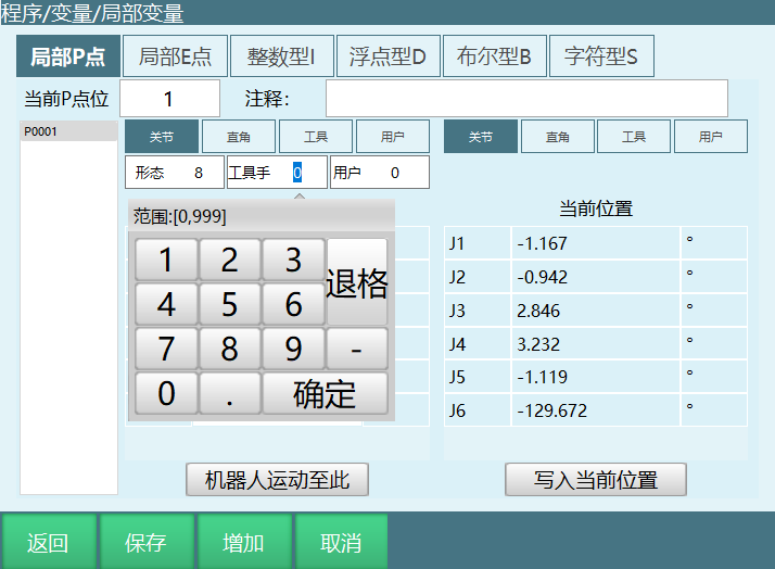
7.4 Tool Hand Parameters
If you want to bind a tool hand to a point, select the corresponding tool hand. To not bind, select "None". If the tool hand during motion differs from the one selected in the point parameters, it cannot run.
For example, binding tool hand 2, but using tool hand 1 to single-step run an instruction using this point.
Controller error (Robot 1 tool coordinate usage error, point user is 1, actual user is 2)
7.5 User Coordinate Parameters
Set user coordinate binding for point positions. To not bind, select "None". If the user coordinate during motion differs from the one bound in the point parameters, it cannot run.
Controller error (Robot 1 user coordinate usage error, point user is 1, actual user is 5)
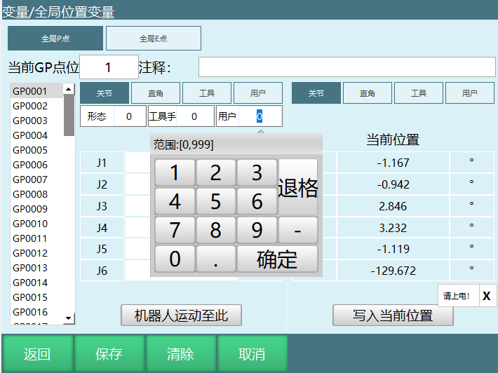
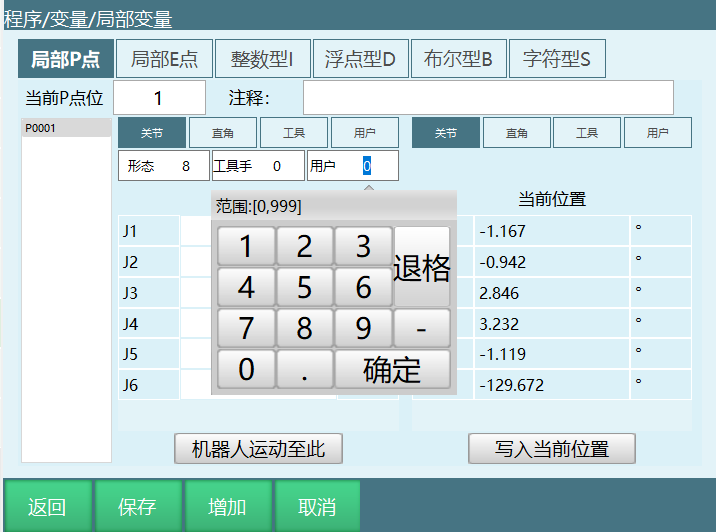
Program local point parameter description:
This function describes the format of point positions saved in programs.
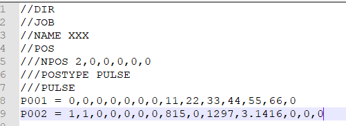
For example, P0002 = 1,1,0,0,0,0,0,815,0,1297,3.1416,0,0,0
Point data breakdown:
| Field | Description |
|---|---|
| P0002 | Point name P0001-P9999 |
| Coordinate system | 0: Joint 1: Cartesian 2: Tool 3: User |
| Angle/Radian | 0: Angle (joint point) 1: Radian (Cartesian, tool, user point) |
| Configuration/Left-right hand | Configuration parameter for six-axis, left-right hand parameter for four-axis SCARA |
| Tool | Tool hand number |
| User | User coordinate number |
| Reserved | Reserved |
| 815 | Axis 1 position value |
| Axis 2 position value | |
| 1297 | Axis 3 position value |
| 3.1416 | Axis 4 position value |
| Axis 5 position value | |
| Axis 6 position value | |
| Axis 7 position value |
8 Robot Teaching and Operation
8.1 Robot Preparation
Power-on and Safety Confirmation
Power-on procedure:
Check that all connection cables of the servo, controller, and teach pendant are properly connected;
Rotate the main power switch on the cabinet panel to the ON position to connect main power;
Press the green servo start button on the cabinet panel.
WARNING

Before teaching, please confirm the emergency stop button is working properly!
Emergency stop button usage verification:
Before using the robot, please verify the emergency stop buttons on the control cabinet and teach pendant respectively. Check whether the servo power is disconnected when pressed;
Press the emergency stop buttons on the control cabinet and teach pendant;
Confirm that the servo power is off, the teach pendant displays a servo error, and the control cabinet servo error light is on;
Switch the servo to ready state;
Clear the servo error, the control cabinet servo error light turns off, and the teach pendant displays "Servo Stopped";
Gently press the [DEADMAN] button on the teach pendant (the button on the back of the teach pendant). The robot powers on, and the teach pendant displays "Servo Running", indicating that the servo power has been successfully connected.
9 Teach Pendant Preparation
9.1 Checking Parameters
Selecting robot type:
Enter [Settings] - [Robot Parameters] - [Slave Configuration] - [Robot Settings];
Click Modify and select the robot type.
Adjusting servos:
Enter [Settings] - [Robot Parameters] - [Slave Configuration] - [Robot Settings];
Jog the robot. Check if J1 controls axis 1, J2 controls axis 2, and so on. If not, modify accordingly.
Note: Some servo slaves have multi-in-one configurations. The robot axes in the slave configuration may not be in the order 1234567.
Adjusting robot actual direction:
Enter [Settings] - [Robot Parameters] - [DH Parameters];
Compare with the robot example image (the marked direction is the positive direction of the jog joint axis). Jog the positive direction of the robot's joint axis. If it does not match, enter [Settings] - [Robot Parameters] - [Joint Parameters] to adjust the model direction.
Adjusting model direction:
When the actual direction of the jogged robot matches the robot example image direction, keep the model direction value unchanged;
When the actual direction of the jogged robot is opposite to the robot example image direction, negate the model direction value.
Adjusting zero position:
The scale on each axis of the robot body is the mechanical zero. Adjust each axis of the robot to the mechanical zero;
Enter [Settings] - [Robot Parameters] - [Zero Position];
Click [Set All Joints to Zero].
Note

If the actual jog of the robot joint axis shows 90 degrees but the teach pendant does not display 90 degrees, the reduction ratio needs to be adjusted or you should confirm with the manufacturer.
If in Cartesian coordinate system, jogging the coordinate axis causes the robot to not move in a straight line, the DH parameters need to be adjusted or you should contact the manufacturer.
9.2 Jogging the Robot
The teach pendant and controller are connected normally;
Servo and robot parameters are normal;
In teach mode, press the [Servo] button on the teach pendant to switch the servo from stopped state to ready state;
Gently press the [DEADMAN] button on the teach pendant (the button on the back of the teach pendant) and do not release it. You will hear the robot power-on sound, and the "Servo State" field displays green "Servo Running";
Control the robot movement by operating the physical buttons on the right side of the teach pendant.
10 Project Interface Basic Operations
Switch to administrator permissions;
Click [Project] on the left side.
10.1 Creating a New Program
To create a new foreground program, follow these steps:
- Enter the [Project] interface, click [New];
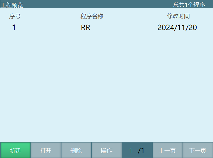
- In the "Program Creation" popup window, enter the program name;
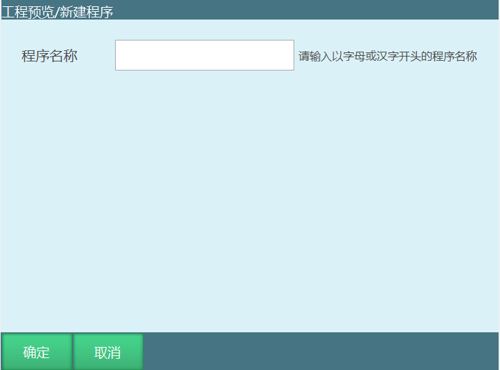
- Click the [OK] button at the bottom. The program is created successfully and the interface jumps to the new program. To cancel creating a new program, click the [Cancel] button.
Note
Program names must be a string of two or more characters starting with a letter or Chinese character.
New program names cannot be the same as existing program names.
10.2 Opening a Program
To open an existing program, follow these steps:
Enter the [Project] interface;
Select the program you want to open;
Click the [Open] button at the bottom. The program is opened successfully.
10.3 Copying a Program
To copy an existing program, follow these steps:
Enter the [Project] interface;
Select the program to copy;
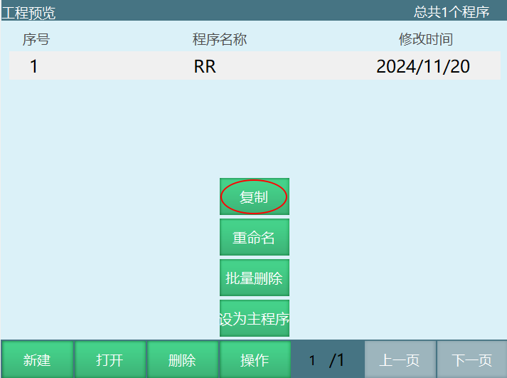
- Click the [Operation] button at the bottom, then click [Copy];
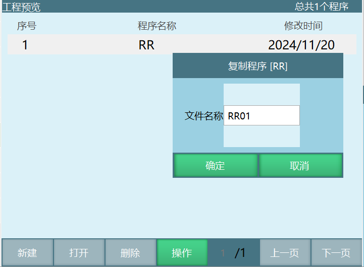
- Click [OK]. You can also modify the program; to cancel the copy, click [Cancel].
10.4 Renaming a Program
The rename operation can modify the name of a selected program.
Operating steps:
Click [Project], select the program you want to rename;
Click [Operation], then click [Rename];
In the popup window, enter the desired new name;
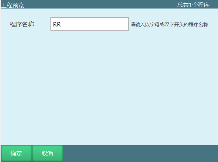
- Click the [OK] button; to cancel the rename operation, click the [Cancel] button.
Note
Renamed program names cannot be the same as existing program names.
Foreground and background program names cannot be duplicated.
10.5 Deleting a Program
The delete operation can delete the selected program.
Operating steps:
Click [Project], select the program you want to delete;
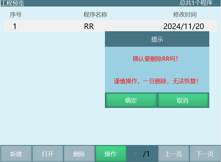
Click the [Delete] button at the bottom;
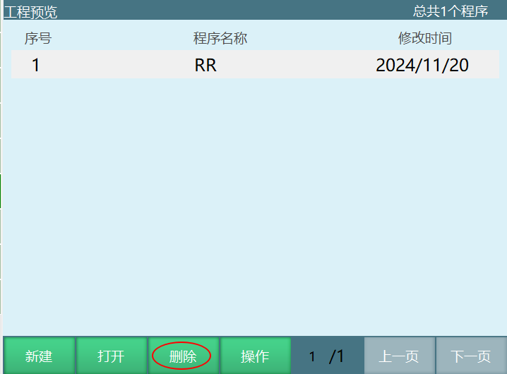
- In the popup window, click the [OK] button; to cancel the delete operation, click the [Cancel] button;
10.6 Batch Delete
The batch delete function can delete multiple programs at once. Usage:
Click [Project];
Click [Operation] in the bottom menu bar, select [Batch Delete];
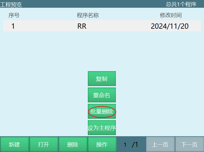
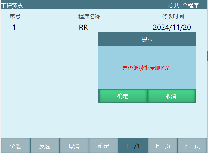
Select the programs to delete. Click the [Select All] button to select all programs on the current page;
After clicking the [OK] button, click [OK] in the confirmation popup to complete batch deletion.
Note
Batch selection can only select files on the current page, not the previous or next page.
11 Program Instruction Writing
11.1 Instruction Operations
To perform instruction-related operations such as insert/modify/delete, enter the program instruction interface and use the bottom buttons for related operations.
11.2 Inserting Instructions
Instructions are inserted using the [Insert] button at the bottom of the program instruction interface;
The inserted instruction appears below the selected instruction line. Up to 9999 points are supported.
Related steps:
Switch to administrator permissions;
Click [Project] on the left side;
Click [New];
Enter the program instruction interface.
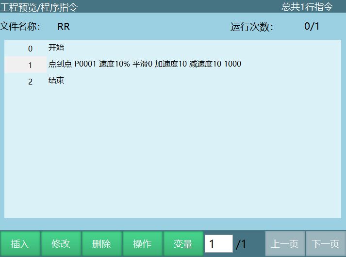
- Click the [Insert] button to open the instruction type menu;
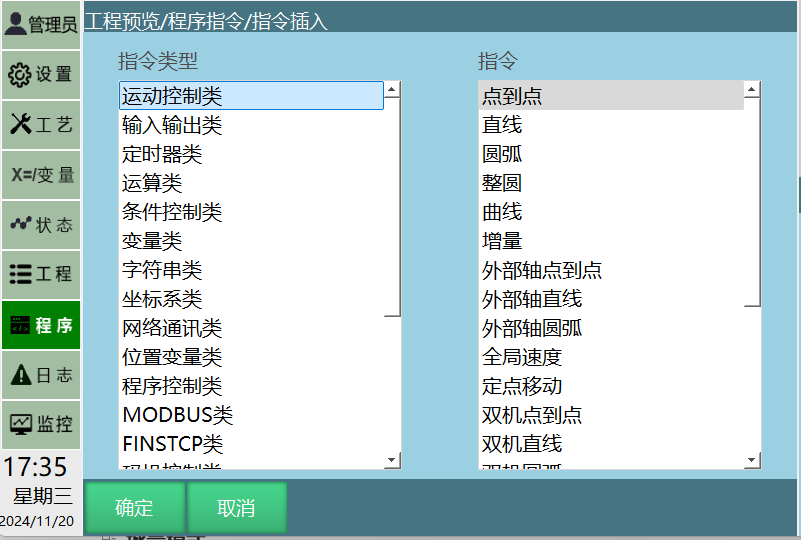
Click the desired instruction type, e.g., Motion Control;
Click the desired instruction, e.g., MOVL, as shown:
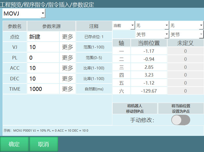
Set the related parameters for the inserted instruction;
Click the [Confirm] button at the bottom.
In batch mode or single-line mode: Modify instructions.
11.3 Batch Mode
You can simultaneously copy, paste, cut, delete, modify, comment out, move up, and move down multiple instructions.
I. If you want to batch copy, paste, cut, delete, modify, comment out, move up, or move down instructions within the current job file, here is the batch copy example:
Click [Operation] - [Batch Mode] at the bottom to enter batch mode;
Select one or more instructions to copy;
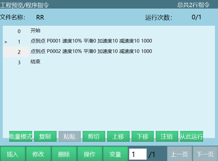
Select the [Copy] button;
Select the instruction above the target location;
Click the [Paste] button.
II. If you want to batch copy, paste, cut, delete, modify, comment out, move up, or move down instructions across job files, here is the batch copy example:
Enter the [Project] interface;
Open the program to copy from;
Click [Operation] - [Batch Mode] at the bottom to enter batch mode;
Select one or more instructions to copy.
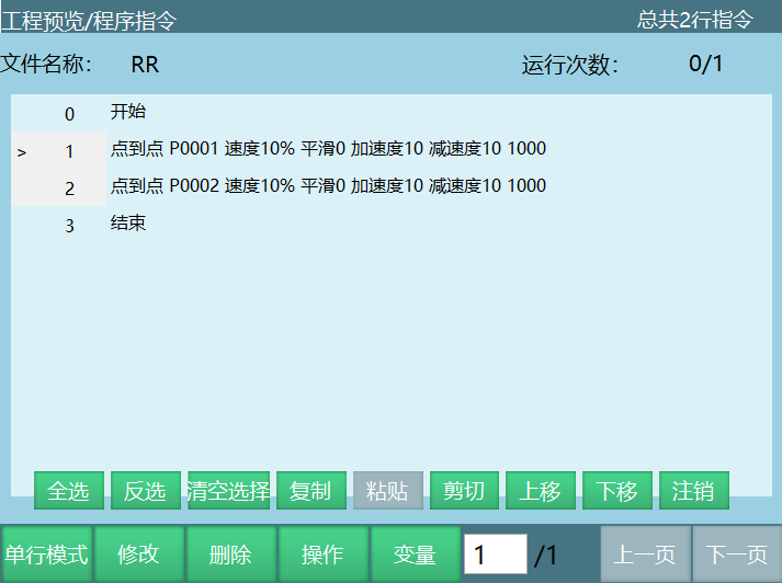
Select the [Copy] button;
Open the target job file to copy to;
Select the instruction above the target location;
Click [Paste].
Single-line mode: Exit batch mode.
Click [Operation] - [Batch Mode] - [Single-line Mode] at the bottom.
Note
Foreground program instructions cannot be copied to background programs!
12 Mode Switching
Users can switch between three modes ("Teach Mode", "Run Mode", "Remote Mode") using the [Mode Selection Key] in the upper right corner of the teach pendant. Programs can run in these three mode states:
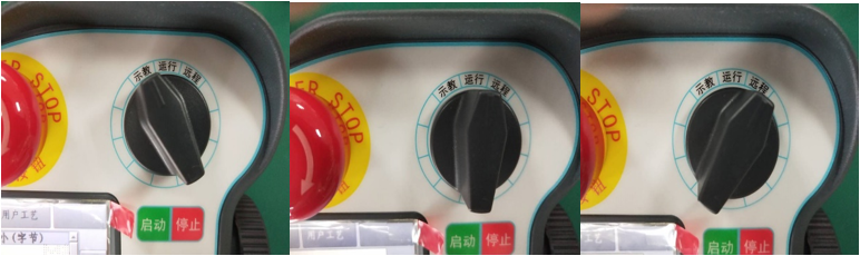
12.1 Teach Mode
In teach mode, you can perform various operations such as system parameter setting, jogging, and job file programming. During job file programming, you can use the [Single-Step] button to perform single-step operations on the job file;
Using the single-step button for trajectory verification

After selecting an inserted instruction line, by holding the [DEADMAN] button and clicking the [Single-Step] button in the physical button area at the bottom of the teach pendant, you can perform single-step operations on the job file being programmed (do not release the [DEADMAN] button during robot movement). Single-step operation only runs the selected instruction line.
Specific steps:
Select the instruction line to perform single-step operation;
Press the [DEADMAN] button to power on the robot;
Press the [Single-Step] button. The robot executes the selected line instruction and stops after execution;
The selected line automatically moves down. To single-step run the next instruction, press the [Single-Step] button again.
12.1.1 Teach Mode Speed
- In teach mode, the robot's actual jog speed calculation is as follows:
| Robot Actual Jog Speed | Max Speed Limit |
|---|---|
| Jogging robot in joint coordinate system | Max joint axis jog speed * teach speed |
| Jogging robot in Cartesian coordinate system | Max Cartesian jog speed * teach speed |
| Home return | Rated speed * teach speed |
| Joint mode safe point return speed | Rated speed * teach speed |
| Linear mode safe point return speed | 100mm/s * teach speed |
| Move to point speed | Rated speed * teach speed |
| Single-step joint speed | Rated speed * (teach speed * instruction speed) |
| Single-step Cartesian speed | Teach speed * instruction speed |
- Example: Calculating robot actual jog speed in joint coordinate system:
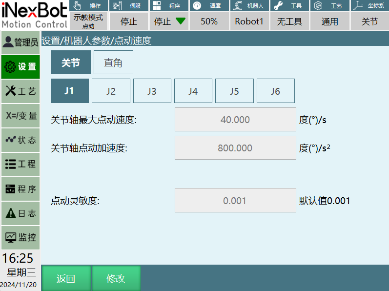
The robot actual jog speed is: {VJ}=40deg/s * 50% = 20deg/s.
Robot max speed limit: With the max joint axis jog speed at 40deg/s, regardless of the teach speed, according to the max speed limit formula (max joint axis jog speed * 50%), the robot actual jog speed is not greater than 20deg/s.
- Max Cartesian speed limit method in joint coordinate system: Adjust "stepMaxDecareSpeed" in the controller configuration file Robot_A.json: 300 (300 is the default speed value, unit is mm/s).
12.1.2 Trial Run Function
The trial run function uses the [Start] button as a trial run button in teach mode. Power on and hold the [Start] button to keep running; release to stop;
Trial run mode supports all instructions;
Trial run does not support reverse order or background programs.
12.2 Run Mode
In run mode, click the [Run Count] button in the lower left corner to set the program run count. Default is [Single Run];
Click the [Loop Run] button in the lower left corner to make the program run in an infinite loop;
In run mode, the number of completed runs and total set runs are displayed above the program, in the format "completed runs/total set runs";
During operation, you can modify the run count. After modification, the robot stops after running the set number of times. For example, if the original setting was 200 runs with 156 completed, and you set the run count to 3, the robot will stop after running three more times.
12.2.1 Run Mode Speed
Run speed = instruction speed * speed ratio in the top status bar.
The default startup speed in run mode can be set by the user in [Operation Parameters].
Note
The instruction speed set during welding is the actual speed. If the linear speed is set to 50mm/s, it means moving 50mm per second.
The run speed after using global speed is: teach speed * instruction speed * global speed.
12.2.2 Run from Current Line
I. In teach mode, open the job file, select a line, click the [Operation] button, click [Run from here]. The job file will display a > symbol, as shown:
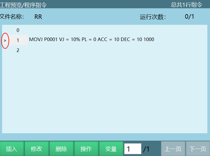
- Switch to run mode, click [Start]. A prompt popup will appear during operation;
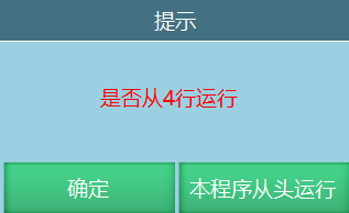
- Click [Confirm] to run from the selected line. Click [Run this program from beginning] to run from the first line of the program;
II. In run mode, when the program runs into a subroutine, switch to teach mode, select a line, click the [Operation] button, click [Run from here]. The job file will display a > symbol.
- Switch to run mode, click [Start]. A prompt popup will appear during operation.
- Click [Confirm] to run from the selected line. After the subroutine finishes, it will return to the main program and continue executing the next instruction.
Click [Run this program from beginning] to run from the first line of the subroutine and it will not return to the main program.
12.3 Breakpoint Execution
12.3.1 Teach Mode Breakpoint
Teach mode also has "breakpoints". During single-step execution, if there are instructions that change local variables, powering off and on again allows you to view the local variable values at the "breakpoint".
Operations such as home return, reset, powering off during single-step instruction, running other programs, running to a point, modifying local numeric/local position variables and single-step instruction, restarting controller, modifying robot parameters, etc., will clear the "breakpoint".
12.3.2 Run Mode Breakpoint
During operation (except the first instruction), switching to another mode causes the run to interrupt. The variable state and program position at the time of interruption are saved as a breakpoint. When running again, a prompt will ask "Continue running current program?" Select "Breakpoint execution" to continue from the breakpoint, or "Restart run" to clear the breakpoint and restart from the first instruction.
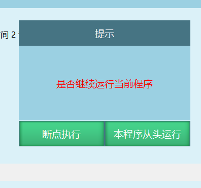
Situations that do NOT clear breakpoints:
IO emergency stop/servo alarm/output message instruction.
Exit the current program, re-enter, and run again.
Jog the robot.
Enter other pages to modify non-robot parameters.
Switch to run mode, select loop run, or modify run count.
Situations that DO create breakpoints:
- Select "Run this program from beginning" in the popup.
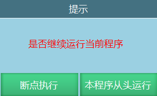
Perform instruction insert/delete/move/cut/copy operations.
Modify local numeric/local position variables/program instructions.
Program instruction error and power off during execution.
Restart controller, modify robot parameters.
Breakpoint status viewing: After a breakpoint, switching to teach mode allows you to view the position/numeric variable state at the breakpoint by powering on.
Example: P0001 and I001 initial states are shown. During operation, P0001 J1+1 and I001+1 change.
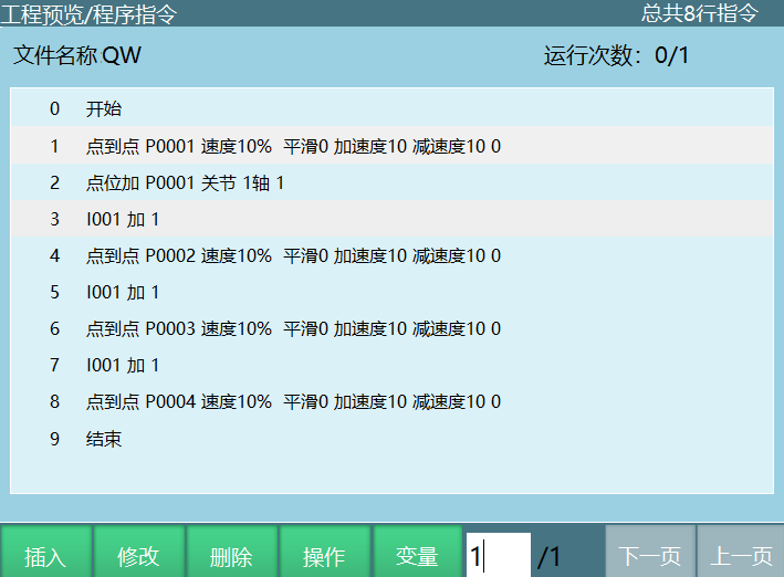
When running to line 6, P0001 J1=1 and I001=2. Switching to teach mode creates a breakpoint. After switching to teach mode, viewing P0001 and I001 shows initial values. Pressing [DEADMAN] to power on shows P0001 J1=1 and I001=2. Powering off restores initial values.
Pre-execution function:
Effective when the motion instruction time parameter is set. Parameter unit is ms.
As shown in the figures:
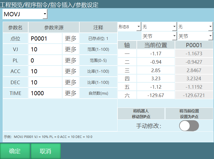
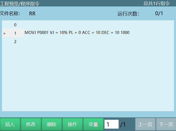
A DOUT instruction is inserted after a MOVJ instruction; The MOVJ instruction TIME parameter is set to 1000ms. During execution, the next instruction will be executed 1 second early. For example, if the MOVJ instruction takes 3 seconds to execute, the DOUT will be executed after 2 seconds of MOVJ execution and then MOVJ continues to P0001.
12.4 Remote Mode
Remote mode supports two control methods: digital IO and Modbus slave.
Device priority: Modbus > digital IO. When both external devices are connected, Modbus touch screen can control the enable of digital IO.
When the teach pendant is unplugged, triggering a remote IO signal will automatically enter remote mode.
Modbus and digital IO can be used simultaneously.
How to enable:
Open the modbusAddr.json file in the config folder
Change "false" after coexistIOControl to "true"
Note
When using Modbus and digital IO simultaneously: Modbus controls program start and stop.
When using Modbus and digital IO simultaneously: Program settings need to be configured in the remote program settings interface.
When using Modbus and digital IO simultaneously: Whether the program supports current line or breakpoint execution needs to be set in the operation parameters page under [Remote IO Breakpoint Execution] and [Remote IO Current Line Execution].
12.4.1 Remote Mode Speed
Remote point-to-point speed = rated speed * remote speed * instruction speed.
Remote linear speed = remote speed * instruction speed.
Remote IO speed modification:
- Enter [Settings] - [Remote Program Settings] - remote parameters interface;
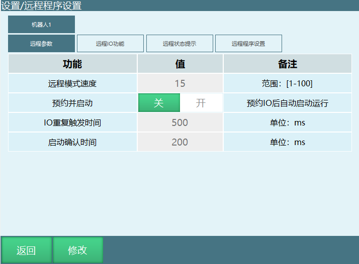
Click [Modify] to change remote mode speed;
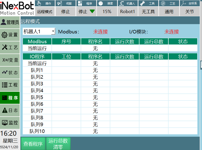
Click [Save], switch to remote mode to view;
12.4.2 Remote Mode Breakpoint
IO reservation programs execute breakpoints by default. If remote breakpoints are not needed, configure in [Settings] - [Operation Parameters] - Remote IO Breakpoint Execution.
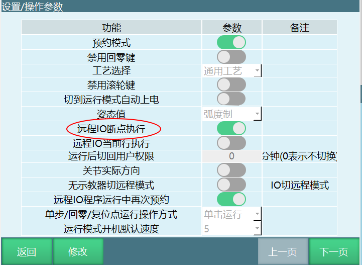
Note
In remote mode, the teach pendant prohibits speed modification. Set it in advance in teach mode. Default remote speed is 15%.
13 Acceleration Adjustment
Function: Improve robot work efficiency. The higher the acceleration multiplier, the faster the robot reaches maximum speed.
Enter [Settings - Robot Parameters - Joint Parameters] to adjust the acceleration multiplier;
When the acceleration multiplier is set to 1, the robot takes 1 second to reach the maximum rated forward speed. If the acceleration multiplier is set to 2, the robot takes 0.5 seconds to reach the maximum rated forward speed, reducing the time by half.
- Time to reach rated speed = (run speed * instruction speed) / (acceleration multiplier * instruction acceleration * run speed)
Example 1: Run speed is 50%, instruction speed is 40%, instruction acceleration is 10%, rated forward speed is 4000 rpm, maximum acceleration is 4x (point-to-point instruction).
- Max instruction speed = rated speed * run speed * instruction speed = 4000rpm * 50% * 40% = 800rpm. Time for robot to go from 0-800rpm = (rated speed * run speed * instruction speed) / (rated speed * acceleration multiplier * run speed * instruction acceleration) = (4000rpm * 40% * 50%) / (4000rpm * 4 * 50% * 10%) = 1s.
Example 2: Run speed is 30%, instruction speed is 1000mm/s, instruction acceleration is 50%, max Cartesian speed is 2000mm/s, max Cartesian acceleration is 2x (linear instruction).
- Max instruction speed = run speed * instruction speed = 1000mm/s * 30% = 300mm/s. Time for robot to go from 0-300mm/s = (run speed * instruction speed) / (max Cartesian speed * Cartesian acceleration multiplier * instruction acceleration * run speed) = (1000mm/s * 30%) / (2000mm/s * 2 * 50% * 30%) = 0.5s.
14 Motion Instructions
14.1 MOVJ - Point-to-Point
Format: MOVJ [instruction name] P/GP [variable] VJ [speed] PL [smoothing] ACC [acceleration ratio] DEC [deceleration ratio] TIME [pre-execution time, displays 0 if not set].
Function: Used in areas where the robot moves to the target point without trajectory constraints. The robot moves from one point to another at the fastest speed in space.
Parameters:
| Parameter | Description |
|---|---|
| Point | Use local position variable (P) or global position variable (GP). When the value is "New", inserting this instruction creates a new P variable and records the robot's current position to that P variable |
| VJ | Joint interpolation speed, range: [1,100] |
| PL | Smoothing transition level, range [0,5] |
| ACC | Acceleration ratio, range [1,100] |
| DEC | Deceleration ratio, range [1,100] |
| TIME | Pre-execution time, unit ms |
Usage example:
1.NOP
2.MOVJ P0001 VJ = 10 % PL =1 ACC = 5 DEC = 5 0
3.MOVJ P0002 VJ = 10 % PL =1 ACC = 5 DEC = 5 0
4.END
14.2 MOVL - Linear
Format: MOVL [instruction name] P/GP [variable] V [speed] PL [smoothing] ACC [acceleration ratio] DEC [deceleration ratio] TIME [pre-execution time, displays 0 if not set].
Function: When the robot moves to the target point, the end-effector trajectory is a straight line.
Parameters:
| Parameter | Description |
|---|---|
| Point | Use local position variable (P) or global position variable (GP). When the value is "New", inserting this instruction creates a new P variable and records the robot's current position to that P variable |
| V | Linear interpolation speed, range 1-1000 (default Cartesian parameter max speed is 1000, range varies based on actual Cartesian parameters), unit mm/s |
| PL | Smoothing transition level, range [0,5] |
| ACC | Acceleration ratio, range [1,100] |
| DEC | Deceleration ratio, range [1,100] |
| TIME | Pre-execution time, unit ms |
Usage example:
1.NOP
2.MOVL P0001 V = 200 mm/s PL = 0 ACC = 20 DEC=20 0
3.MOVL P0002 V = 200 mm/s PL = 0 ACC = 20 DEC=20 0
4.MOVL P0003 V = 200 mm/s PL = 0 ACC = 20 DEC=20 0
5.MOVL P0004 V = 200 mm/s PL = 0 ACC = 20 DEC=20 0
6.END
14.3 MOVC - Circular Arc
Format: MOVC [instruction name] P/GP [variable] V [speed] PL [smoothing] ACC [acceleration ratio] DEC [deceleration ratio] TIME [pre-execution time, displays 0 if not set].
Function: Move to three taught points using circular arc interpolation.
Parameters:
| Parameter | Description |
|---|---|
| Point | Use local position variable (P) or global position variable (GP). When the value is "New", inserting this instruction creates a new P variable and records the robot's current position to that P variable |
| V | Linear interpolation speed, range 1-1000 (default Cartesian parameter max speed is 1000, range varies based on actual Cartesian parameters), unit mm/s |
| PL | Smoothing transition level, range [0,5] |
| ACC | Acceleration ratio, range [1,100] |
| DEC | Deceleration ratio, range [1,100] |
| TIME | Pre-execution time, unit ms |
| SPIN | Taught posture: Posture runs directly from the first point to the third point. Constant inclination: Maintains the inclination of the first point throughout the entire trajectory (regardless of the posture of the second and third points). Variable representation: 0 = taught posture, 1 = constant inclination |
Note: To complete a full circular arc trajectory, you need to insert one MOVJ or MOVL instruction followed by two MOVC instructions, otherwise the program will report an error (Robot 1 instruction error, isolated MOVC instruction).
Usage example:
NOP
MOVL P0001 V=100mm/s PL=0 ACC=1 DEC=1 0
MOVL P0002 V=100mm/s PL=0 ACC=1 DEC=1 0          Arc start point
MOVC P0003 V=100mm/s PL=0 ACC=10 DEC=10 0     Arc midpoint
MOVC P0004 V=100mm/s PL=0 ACC=10 DEC=10 0     Arc end point
END
14.4 MOVCA - Full Circle
Format: MOVCA [instruction name] P/GP [variable] V [speed] PL [smoothing] ACC [acceleration ratio] DEC [deceleration ratio] TIME [pre-execution time, displays 0 if not set].
Function: The robot moves in a full circle trajectory through three taught points.
Parameters:
| Parameter | Description |
|---|---|
| Point | Use local position variable (P) or global position variable (GP). When the value is "New", inserting this instruction creates a new P variable and records the robot's current position to that P variable |
| V | Linear interpolation speed, range 1-1000 (default Cartesian parameter max speed is 1000, range varies based on actual Cartesian parameters), unit mm/s |
| PL | Smoothing transition level, range [0,5] |
| ACC | Acceleration ratio, range [1,100] |
| DEC | Deceleration ratio, range [1,100] |
| TIME | Pre-execution time, unit ms |
| SPIN | Constant posture: The full circle posture is the same as the first point's taught posture (MOVJ, MOVL calibration posture) and maintains this posture throughout the full circle. Axis 6 fixed: The full circle runs according to each point's taught posture, while axis 6 remains fixed. Axis 6 rotating: The full circle runs according to each point's taught posture |
Note: To complete a full circle trajectory, you need to insert one MOVJ or MOVL instruction followed by two MOVCA instructions, otherwise the program will report an error (Robot 1 instruction error, isolated MOVCA instruction).
Usage example:
NOP
MOVL P0001 V=50mm/s PL=0 ACC=1 DEC=1 0
MOVL P0002 V=50mm/s PL=0 ACC=1 DEC=1 0               Full circle start point
MOVC P0003 V=100mm/s PL=0 ACC=10 DEC=10 0        Full circle transition point
MOVC P0004 V=100mm/s PL=0 ACC=10 DEC=10 0        Full circle end point
END
14.5 MOVS - Curve
Format: MOVS [instruction name] P/GP [variable] V [speed] PL [smoothing] ACC [acceleration ratio] DEC [deceleration ratio] TIME [pre-execution time, displays 0 if not set].
Function: For welding, cutting, fusion, priming, and other operations, using free curve interpolation makes teaching operations for irregular curve workpieces easier.
Parameters:
| Parameter | Description |
|---|---|
| Point | Use local position variable (P) or global position variable (GP). When the value is "New", inserting this instruction creates a new P variable and records the robot's current position to that P variable |
| V | Linear interpolation speed, range 1-1000 (default Cartesian parameter max speed is 1000, range varies based on actual Cartesian parameters), unit mm/s |
| PL | Smoothing transition level, range [0,5] |
| ACC | Acceleration ratio, range [1,100] |
| DEC | Deceleration ratio, range [1,100] |
| TIME | Pre-execution time, unit ms |
Note: Curve trajectories require at least four taught curve points, otherwise the program will report an error (Robot 1 instruction error, MOVS instructions cannot be less than 4).
Example: Use curve interpolation to teach four points, forming a curve trajectory.
Usage example:
NOP
MOVL P0001 V = 100mm/s  PL = 0 ACC = 10 DEC = 10 0        Safe point
MOVS P0002 V = 100 mm/s PL = 0 ACC = 10 DEC = 10 0        Curve start point
MOVS P0003 V = 100mm/s  PL = 0 ACC = 10 DEC = 10 0        Curve midpoint
MOVS P0004 V = 100 mm/s PL = 0 ACC = 10 DEC = 10 0        Curve midpoint
MOVS P0005 V = 100 mm/s PL = 0 ACC = 10 DEC = 10 0        Curve midpoint
MOVS P0006 V = 100mm/s  PL = 0 ACC = 10 DEC = 10 0        Curve end point
MOVL P0007 V = 100mm/s  PL = 0 ACC = 10 DEC = 10 0        End point of entire trajectory
END
14.6 IMOV - Incremental
Format: IMOV [instruction name] RP [variable] V/VJ [speed] RF BF TF UF [coordinate system] PL [smoothing] ACC [acceleration ratio] DEC [deceleration ratio] TIME [pre-execution time, displays 0 if not set].
Function: Move from the current position by a set increment value using joint or linear interpolation.
Parameters:
| Parameter | Description |
|---|---|
| RP | Increment variable, records incremental position data |
| V/VJ | V: Linear interpolation speed; VJ: Joint interpolation speed |
| PL | Smoothing transition level, range [0,5] |
| Coordinate system | Joint, Cartesian, tool, user |
| ACC | Acceleration ratio, range [1,100] |
| DEC | Deceleration ratio, range [1,100] |
| TIME | Pre-execution time, unit ms |
Note: Error handling: When inserting an incremental instruction, if the coordinate system selected is tool coordinate, the point tool must match the actual tool in use, otherwise the program will report an error (e.g., Robot 1 tool hand usage error, point tool is 1, actual tool is 2).
Example:
The coordinate system can be joint, Cartesian, tool, or user. Fill positive values for positive direction, negative for reverse, and 0 for no movement.
| Coordinate System | Position Parameter | Example |
|---|---|---|
| Joint (RF) | J1-(10) J2-(-5) J3-0 J4-0 J5-0 J6-0 | IMOV RP0001 VJ=10% RF PL=0 ACC=1 DEC=1 0 - Robot axis J1 increases by 10, J2 decreases by 5, other axes unchanged |
| Cartesian (BF) | X-(-20) Y-(35) Z-(50) A-0 B-0 C-0 | IMOV RP0002 V=10mm/s BF PL=0 ACC=1 DEC=1 0 - X-axis decreases 20mm, Y-axis increases 35mm, Z-axis increases 50mm, others unchanged |
| Tool (TF) | TX-(10) TY-(20) TZ-(-30) TA-(1) TB-0 TC-0 | IMOV RP0003 V=10mm/s TF PL=0 ACC=1 DEC=1 0 - TX increases 10mm, TY increases 20mm, TZ decreases 30mm, TA increases 1rad, others unchanged |
| User (UF) | UX-(0) UY-(-20) UZ-(30) UA-(0) UB-(-1) UC-0 | IMOV RP0004 V=10mm/s UF PL=0 ACC=1 DEC=1 0 - UY decreases 20mm, UZ increases 30mm, UB decreases 1rad, others unchanged |
14.7 MOVJEXT - External Axis Point-to-Point
Format: MOVJEXT [instruction name] E/GE [variable] VJ [speed] PL [smoothing] ACC [acceleration ratio] DEC [deceleration ratio] TIME [pre-execution time, displays 0 if not set].
Function: The robot moves to the taught position using joint interpolation. When the external axis rotates, the robot moves on the external axis through the taught points.
Parameters:
| Parameter | Description |
|---|---|
| E/GE | Variable recording robot and external axis position data. When "New", inserts a new E variable and records current positions |
| VJ | Joint interpolation speed, range [1,100] |
| EVJ | External axis speed, range [1,100] |
| PL | Smoothing transition level, range [0,5] |
| ACC | Acceleration ratio, range [1,100] |
| DEC | Deceleration ratio, range [1,100] |
| TIME | Pre-execution time, unit ms |
Usage example:
NOP
MOVJEXT E0001 VJ = 10 % PL = 0 ACC= 10 DEC = 10 0
MOVJEXT E0002 VJ = 20 % PL = 0 ACC= 10 DEC = 10 0
END
14.8 MOVLEXT - External Axis Linear
Format: MOVLEXT [instruction name] E/GE [variable] V [speed] PL [smoothing] ACC [acceleration ratio] DEC [deceleration ratio] SYNC [positioner sync, "0" = no sync, "1" = sync enabled] TIME [pre-execution time, displays 0 if not set].
Function: The robot moves to the taught position using linear interpolation. When the external axis rotates, the robot moves in a straight line on the external axis.
Parameters:
| Parameter | Description |
|---|---|
| E/GE | Variable recording robot and external axis position data |
| V | Linear interpolation speed, range 1-1000, unit mm/s |
| EVJ | External axis speed, range [1,100] |
| PL | Smoothing transition level, range [0,5] |
| ACC | Acceleration ratio, range [1,100] |
| DEC | Deceleration ratio, range [1,100] |
| TIME | Pre-execution time, unit ms |
| SYNC | Positioner sync: On = robot and external axis move linearly together; Off = robot moves linearly in space while external axis moves independently to target |
Usage example:
NOP
MOVLEXT E0001 V = 50 mm/s PL = 0 ACC = 1 DEC = 1 SYNC = 1 0
MOVLEXT E0002 V = 50 mm/s PL = 0 ACC = 1 DEC = 1 SYNC = 1 0
END
14.9 MOVCEXT - External Axis Circular Arc
Format: MOVCEXT [instruction name] E/GE [variable] V [speed] PL [smoothing] ACC [acceleration ratio] DEC [deceleration ratio] SYNC [positioner sync, "0" = no sync, "1" = sync enabled] TIME [pre-execution time, displays 0 if not set].
Function: The robot moves to the taught position using circular arc interpolation, while the external axis uses joint interpolation. The robot end-effector moves in a circular arc from E0001-E0003, and the external axis rotates during the arc.
Parameters: Same as MOVLEXT.
Usage example:
NOP
MOVL E0001 V = 100 mm/s PL = 0 ACC = 1 DEC = 1 0                       Safe point
MOVLEXT E0002 V = 50 mm/s PL = 0 ACC = 1 DEC = 1 SYNC = 1 0  Arc start point
MOVCEXT E0003 V = 50 mm/s PL = 0 ACC = 1 DEC = 1 SYNC = 1 0  Arc midpoint
MOVCEXT E0004 V = 50 mm/s PL = 0 ACC = 1 DEC = 1 SYNC = 1 0  Arc end point
END
14.10 SPEED - Global Speed
Format: SPEED [instruction name] 10% [speed parameter].
Function: Globally modify the speed of motion instructions below the SPEED instruction.
Parameters:
| Parameter | Description |
|---|---|
| SPEED | Range [1,200]% |
| Manual | Directly input speed parameter |
| Variable | Set speed parameter by assigning to a variable |
Note: Speed calculation for motion instructions below the SPEED instruction:
Linear speed: instruction speed * status bar speed * SPEED global speed percentage.
Axis speed: joint rated forward speed * instruction speed * status bar speed * SPEED global speed percentage.
During program execution, you can view current speed and maximum speed in the Monitor - Axis Speed interface.
Usage example:
NOP
MOVL GP0001 V = 200 mm/s PL = 2 ACC = 20 DEC=20 0
MOVL GP0002 V = 200 mm/s PL = 2 ACC = 20 DEC=20 0
SPEED= 80%
MOVL GP0003 V = 100 mm/s PL = 2 ACC = 20 DEC=20 0
MOVL GP0004 V = 100 mm/s PL = 2 ACC = 20 DEC=20 0
MOVL GP0005 V = 100 mm/s PL = 2 ACC = 20 DEC=20 0
END
14.11 SAMOV - Fixed-Point Move
Format: SAMOV [instruction name] AP [variable] V/VJ [speed] RF BF TF UF [coordinate system] PL [smoothing] ACC [acceleration ratio] DEC [deceleration ratio] TIME [pre-execution time, displays 0 if not set].
Function: Robot moves to the set position using fixed-point movement.
Parameters: AP (fixed-point move variable), V/VJ (speed), PL (smoothing), coordinate system, ACC/DEC (acceleration/deceleration), TIME (pre-execution time).
Usage example: SAMOV AP0001 VJ= 10 % PL= 2 ACC= 10 DEC= 10
14.12 MOVJDOUBLE - Dual Robot Point-to-Point
Format: MOVJDOUBLE [instruction name] E/GE [variable] VJ [speed] ACC [acceleration ratio] DEC [deceleration ratio] TIME [pre-execution time, displays 0 if not set].
Function: Two robots move from one point to another using joint interpolation.
Usage example:
NOP
MOVJDOUBLE E0001 VJ = 10 % PL = 0 ACC= 10 DEC = 10 0
MOVJDOUBLE E0002 VJ = 15 % PL = 0 ACC= 10 DEC = 10 0
END
Example description: When the program starts, both robots move from E0001 to E0002 using joint interpolation based on taught points.
14.13 MOVLDOUBLE - Dual Robot Linear
Format: MOVLDOUBLE [instruction name] E/GE [variable] V [speed] ACC [acceleration ratio] DEC [deceleration ratio] TIME [pre-execution time, displays 0 if not set].
Function: Controls two robots to run to the target position using linear interpolation. The end-effector trajectory is a straight line.
Usage example:
NOP
MOVLDOUBLE E0001 V = 100 mm/s PL = 0 ACC= 10 DEC = 10 0
MOVLDOUBLE E0002 V = 50 mm/s PL = 0 ACC= 10 DEC = 10 0
MOVLDOUBLE E0003 V = 50 mm/s PL = 0 ACC= 10 DEC = 10 0
MOVLDOUBLE E0004 V = 50 mm/s PL = 0 ACC= 10 DEC = 10 0
END
14.14 MOVCDOUBLE - Dual Robot Circular Arc
Format: MOVCDOUBLE [instruction name] E/GE [variable] V [speed] ACC [acceleration ratio] DEC [deceleration ratio] TIME [pre-execution time, displays 0 if not set].
Function: Two robots move in a circular arc trajectory when the program starts.
Usage example:
NOP
MOVLDOUBLE E0001 V = 10 % PL = 0 ACC= 10 DEC = 10 0
MOVLDOUBLE E0002 V = 10 % PL = 0 ACC= 10 DEC = 10 0              Arc start point
MOVCDOUBLE E0003 V = 100 mm/s PL = 0 ACC= 10 DEC = 10 0    Arc transition point
MOVCDOUBLE E0004 V = 100mm/s PL = 0 ACC= 10 DEC = 10 0     Arc end point
END
14.15 MOVCADOUBLE - Dual Robot Full Circle
Format: MOVCADOUBLE [instruction name] E/GE [variable] V [speed] ACC [acceleration ratio] DEC [deceleration ratio] TIME [pre-execution time, displays 0 if not set].
Function: The robot performs a full circle trajectory through dual-robot collaboration.
SPIN: End-effector rotation. Same options as MOVCA.
Usage example:
NOP
MOVLDOUBLE E0001 V = 10 % PL = 0 ACC= 10 DEC = 10 0
MOVLDOUBLE E0002 V = 10 % PL = 0 ACC= 10 DEC = 10 0               Full circle start point
MOVCADOUBLE E0003 V = 25 mm/s PL = 0 ACC= 10 DEC = 10 0      Full circle transition point
MOVCADOUBLE E0004 V = 25 mm/s PL = 0 ACC= 10 DEC = 10 0      Full circle end point
END
14.16 MOVCOMM - External Point
Format: MOCOMM [instruction name] MOVJ/MOVL/MOVS/MOVC [interpolation method] V/VJ [speed] PL [smoothing] ACC [acceleration ratio] DEC [deceleration ratio] TIME [pre-execution time, displays 0 if not set].
Function: Move to the target position using the specified interpolation method through the external point instruction. External point positions can be sent via 6000/7000 ports and vision processes.
Example 1:
NOP
VISION_RUN ID =1                                                        Vision start
VISION_TRG ID =1                                                         Vision trigger
VISION_TRACE ID =1                                                     Get vision trajectory position
MOCOMM MOVJ VJ=10% PL=0 ACC=10 DEC=10 0    External point
VISION_END ID =1                                                        Vision end
END
14.17 EXTMOV - External Axis Following
Format: EXTMOV [instruction name] O1 [following external axis] COMST_T [following type] 10 [multiplier].
Function: External axis follows the robot at a speed that is a multiple of the robot's linear speed or at a constant speed.
Parameters:
| Parameter | Description |
|---|---|
| External axis | Select O1-O5 axis for following |
| Type | Following: Speed changes with robot's real-time speed; Constant: Runs at a constant speed |
| Speed value | When type is constant, speed value can be manually entered or via variable; When type is following, a K (multiplier) value can be entered. External axis speed (deg/s) = K * linear speed (mm/s) |
Note: External axis motion instructions cannot be inserted between external axis following instructions!
14.18 GEARIN - Electronic Gear
Format: GEARIN [instruction name] J1 [master axis] O1 [following axis] K=2 [ratio].
Function: An external axis follows a robot axis to move together. The following external axis speed equals the selected master axis speed multiplied by the ratio K.
Usage example:
NOP
GEARIN J1 O1 2                                                                  Electronic gear start
MOVL P0001 V=10mm/s PL=0 ACC=1 DEC=1 0                       Linear instruction
ENDGEARIN                                                                        Electronic gear stop
END
14.19 MRESET - Reset External Axis Multi-Turn Rotation
Format: MRESET [instruction name] 1 [external axis to reset].
Function: After an external axis exceeds its limit, this instruction resets the external axis coordinates so it won't error due to limit exceeded.
14.20 DRAG_TRAJECTORY - Drag Teaching
Format: DRAG_TRAJECTORY [instruction name] Track [trajectory name] 20% [playback speed].
Function: Run the recorded drag trajectory through an instruction.
Usage example:
NOP
DRAG_TRAJECTORY ##Track1$$ 20%               Run recorded trajectory 1
END
14.21 SWITCHPAYLOAD - Switch Payload Parameters
Format: SWITCHPAYLOAD [instruction name] 1 [payload number].
Function: Used to switch payload parameters.
14.22 MOVARCH - Arch Motion
Format: MOVARCH [instruction name] P/GP [variable] V [speed] PL [smoothing] ACC [acceleration ratio] DEC [deceleration ratio] X/Y/Z [displacement axis] 150 [displacement distance] 100 [linear distance] TIME [pre-execution time, displays 0 if not set].
Function: Robot moves in an arch trajectory.
Standard arch trajectory: height 25mm, width 300mm.
Note: Linear distance cannot be greater than displacement distance.
Usage example:
NOP
MOVARCH P0001 V=10 PL=0 ACC=10 DEC=10 Z 25 0
MOVARCH P0002 V=10 PL=0 ACC=10 DEC=10 Z 25 0
END
15 Input/Output Instructions
15.1 DIN - IO Input
Format: DIN [instruction name] I001 [variable to store port value] IGH [input channels] 1 [input group number].
Function: Digital input converts external signals to high or low voltage/current levels and passes them to the control system. Used to receive external digital signals, typically for detecting switch states, sensor signals, etc.
15.2 DOUT - IO Output
Format: DOUT [instruction name] OT [output channels] (DOUT1-1) [output group number] 1 [output port] T=1 [time] 1 [error stop handling, "0" = output value hold, "1" = timer end stop].
Function: Digital output is used to control external devices and does not accept feedback signals, such as relays, switches, etc.
15.3 AIN - Analog Input
Format: AIN [instruction name] D001 [variable value] AIN1-1 [analog input port].
Function: Can receive continuously varying signals. Common analog input signals include voltage, current, etc.
Usage example:
NOP
AIN D001 AIN1-1
END
15.4 AOUT - Analog Output
Format: AOUT [instruction name] AOUT1-1 [analog output port] GD001/D001 [variable value source].
Function: Can output continuously varying signals. Common analog output signals include voltage, current, etc.
Usage example:
NOP
GD001=5
AOUT AOUT1-1 GD001
END
15.5 PULSEOUT - Pulse Output
Format: PULSEOUT [instruction name] RATE [frequency] SUM [count].
Function: Outputs pulses at the set frequency and count on pin 4 (PWM+) of the DB9 terminal on the R1 PWMIO board.
15.6 READ_DOUT - Read Output
Format: READ_DOUT [instruction name] GI001 [variable type] OT [output channels] (DOUT1-1) [output group number].
Function: Reads the digital output port status through a variable, then converts binary to decimal and stores it in the target variable.
16 Timer Instructions
16.1 TIMER - Delay
Function: Delays program execution for the set value. After reaching the set value, the program continues running.
Usage example: TIMER T= 10 (delay 10 seconds).
17 Arithmetic Instructions
17.1 ADD - Addition
Function: Addition operation (+), A=A+B.
Usage example: ADD GI001 22; meaning: variable GI001 plus 22.
17.2 SUB - Subtraction
Function: Subtraction operation (-), A=A-B.
Usage example: SUB GI001 22; meaning: variable GI001 minus 22.
17.3 MUL - Multiplication
Function: Multiplication operation (), A=AB.
Usage example: MUL GI001 22; meaning: variable GI001 times 22.
17.4 DIV - Division
Function: Division operation (/), A=A/B.
Usage example: DIV GI001 22; meaning: variable GI001 divided by 22.
17.5 MOD - Modulo
Format: MOD [instruction name] I001 [result variable] I002 [parameter].
Function: Performs modulo operation and stores the result in the selected result variable.
Usage example:
NOP
SET GI001=11
MOD GI001 7
TIMER T=2
END
17.6 SIN - Sine
Format: SIN [instruction name] I001 [result variable] I002 [parameter].
Function: Sine operation (sin), A=sin(B), B is in radians.
17.7 COS - Cosine
Format: COS [instruction name] I001 [result variable] I002 [parameter].
Function: Cosine operation (cos), A=cos(B), B is in radians.
17.8 ATAN - Arctangent
Format: ATAN [instruction name] I001 [result variable] I002 [parameter].
Function: Arctangent operation (arctan), A=arctan(B), B is in radians.
17.9 LOGICAL_OP - Logical Operation
Format: LOGICAL_OP [instruction name] B001 [result variable] = I001 [parameter 1] AND/OR/NOT [operation type] GI001 [parameter 2].
Function: Logical operations (AND, OR, NOT).
Operation types: AND (&&), OR (||), NOT (!).
18 Condition Control Instructions
Current judgment instructions support multi-condition sequential judgment. Parenthesized conditions are evaluated first, then conditions outside parentheses. Maximum of 5 judgment conditions supported.
Note: When condition judgment requires string comparison, the actual comparison uses the ASCII code values of the characters.
18.1 CALL - Call Subroutine
Format: CALL [instruction name] [$subroutine$] [program filename] IN(12) [input parameters] OUT(GI001) [output parameters].
Function: Calls another program.
Note: Main program A calling program B, and program B calling program A will cause an infinite loop.
18.2 CALL_LUAFILE - Call LUA File
Format: RETURN [instruction name].
Function: Exits the currently running job file, such as subroutine or background program.
18.3 IF - If
Format: IF [instruction name] I001 [parameter 1] = [comparison method] D001 [parameter 2].
Function: Executes the next target instruction based on whether the condition is true.
Comparison methods: == (equal), < (less than), > (greater than), <= (less than or equal), >= (greater than or equal), != (not equal).
Note: IF can be used alone or with ELSEIF and ELSE. ELSEIF and ELSE cannot be used independently without IF.
When the program starts with IF and ends with ENDIF, insert a 0.1-second TIMER instruction above IF or below ENDIF, otherwise the program may freeze when the IF condition is not met.
Usage example:
NOP
MOVL P0001 V=10mm/s PL=0 ACC=1 DEC=1 0
IF (GI001>5)AND{(GI002=5)OR(D001!=3)}
TIMER T=2
ENDIF
END
18.4 ELSEIF - Else If
Format: ELSEIF [instruction name] I001 [parameter 1] = [comparison method] D001 [parameter 2].
Function: When the IF condition is not met, the ELSEIF statement is executed.
18.5 ELSE - Else
Function: ELSE must be inserted between IF and ENDIF. Only one ELSE instruction can be embedded in an IF instruction.
18.6 WAIT - Wait
Format: WAIT [instruction name] GI001 [parameter 1] == [comparison method] 2 [parameter 2] T = 2 [wait time] F = 1 [filter time] Return=B001 [wait result stored in variable].
Function: The program waits until the condition is met, then continues executing instructions after the WAIT instruction.
18.7 WHILE - Loop
Format: WHILE [instruction name] I001 [parameter 1] = [comparison method] D001 [parameter 2].
Function: When the condition is true, repeatedly executes instructions inside the loop.
Note: Inserting a WHILE instruction also inserts an ENDWHILE instruction. When deleting a WHILE instruction, also delete the corresponding ENDWHILE.
Usage example:
NOP
CALL[$Z Subroutine$]
WHILE(DIN1-1=1)OR(GI001=1)
MOVL P0001 V=10mm/s PL=0 ACC=1 DEC=1 0
MOVL P0002 V=10mm/s PL=0 ACC=1 DEC=1 0
ENDWHILE
TIMER T=1
END
18.8 LABEL - Label
Format: LABEL [instruction name] [$name$] [label name].
Function: Specifies the target line label for jumps.
Note: Two label instructions with the same name cannot be inserted in the same program.
18.9 JUMP - Jump
Format: JUMP [instruction name] [$TIP$] [label name] WHEN(I001=0) [condition].
Function: Jumps to the instruction line with the specified label.
Note: JUMP instructions must be used with LABEL instructions. JUMP cannot jump across programs.
Usage example:
NOP
MOVL P0001 V=10mm/s PL=0 ACC=1 DEC=1 0
LABEL [$Q1$]
MOVL P0002 V=10mm/s PL=0 ACC=1 DEC=1 0
MOVL P0003 V=10mm/s PL=0 ACC=1 DEC=1 0
JUMP [$Q1$] WHEN(GI001!=10)AND(GI002>5)
TIMER T=1
END
18.10 UNTIL - Until
Format: UNTIL [instruction name] I001 [variable 1] = [comparison method] I002 [variable 2].
Function: Repeats instructions between UNTIL and ENDUNTIL when the condition is not met. Jumps to instructions after ENDUNTIL when the condition is met.
18.11 CMDNOTE - Comment Instruction
Format: ##comment content$$.
Function: Adds comments at appropriate positions in the program for easier debugging.
18.12 POS_REACHABLE - Reachability Check
Format: POS_REACHABLE [instruction name] MOVL/MOVJ [motion type] B001 [status variable].
Function: Determines whether a target point can be reached. If reachable, the status variable is set to 1; if not, set to 0.
18.13 CLKSTART - Timer Start
Format: CLKSTART [instruction name] ID=1 [timer number] D001 [variable to store time].
Function: Starts timing and records the time to a local or global DOUBLE variable.
18.14 CLKSTOP - Timer Stop
Format: CLKSTOP [instruction name] ID=1 [timer number to stop].
Function: Stops the corresponding timer. The value already stored in the variable is not reset.
18.15 CLKRESET - Timer Reset
Format: CLKRESET [instruction name] ID=1 [timer number to reset].
Function: Resets the corresponding timer to zero.
18.16 READLINEAR - Read Linear Speed
Format: READLINEAR [instruction name] GI001 [variable to store value].
Function: Reads the robot's linear speed in real-time during operation and stores the read speed in a variable.
18.17 CALL_LUASTRING - Call LUA Statement
Format: CALL_LUASTRING [instruction name] [$statement$] [Lua input].
Function: Implements functions or operations by calling Lua statements, such as modifying variables, obtaining global/local positions.
Usage example:
NOP
SET GS005=#nex.GI[5]=12#
CALL_LUASTRING GS005
CALL_LUASTRING #nex.dout[1,1]#
END
18.18 WAIT_POS - Wait for Position Reached
Format: WAIT_POS [instruction name] SPEED/POS [speed/position] ACCURACY [accuracy] MINTIME [minimum wait time] MAXTIME [maximum wait time].
Function: The MOV instruction finishing does not mean the servo has finished running - it only means the position has been sent. This instruction waits for the servo motor to reach the precise position before executing the next instruction.
Note: This instruction must be executed after a motion instruction. It only supports foreground programs. It does not support pre-execution.
19 Variable Instructions
19.1 SET - Assignment
Format: SET [variable name] I001 [target variable] 3 [value].
Function: Assigns values to defined integer, floating-point, boolean, and string variables.
Usage example:
NOP
SET I001=12
SET D001=12.21
SET GI012=100
SET GI[GI012]=999
END
Note: When setting string types, if the string contains escape characters, add "\" before the escape character to avoid its effect.
19.2 FORCESET - Write to File
Format: FORCESET [instruction name] GI001 [variable name to write].
Function: Saves buffered data to disk.
During program execution, all calculation and assignment operations modify values in the buffer and are not saved to system files. To force writing global numeric variables from memory to files, use the FORCESET instruction.
20 String Instructions
20.1 STRING_SPELL - String Append
Format: STRING_SPELL [instruction name] S001 [target variable] S002 [value to append].
Function: Appends desired characters to an existing string variable or new string variable to form a new string variable.
Usage example:
NOP
SET S001=#@QWE123#
STRING_SPELL(S001+#!ASD234@#)
STRING_SPELL(GS001+#INEXBOT#)
END
20.2 STRING_SLICE - String Index Slice
Format: STRING_SLICE [instruction name] S001 [target variable] (I001,I002) [start index, end index] S002 [output variable].
Function: Extracts a portion of a string variable and stores the extracted part in a specified variable.
20.3 STRING_SPLIT - String Delimiter Split
Format: STRING_SPLIT [instruction name] S001 [variable to split] , [delimiter] S002 [first output variable] I001 [count variable, "0" = not used].
Function: Splits a string variable by a delimiter character and stores the split parts sequentially in specified variables.
20.4 STRING_LOCATE - String Locate Query
Format: STRING_LOCATE [instruction name] GS001 [variable to query] #T# [search character] GI001 [first output variable] GI005 [count variable].
Function: Queries the position of a character within a string variable and stores the position and count in specified variables.
20.5 STRING_LENGTH - String Length
Format: STRING_LENGTH [instruction name] S001 [variable to measure] I001 [output variable].
Function: Calculates the length of a string variable and stores the length in a variable.
20.6 STRING_TO - String to Non-String
Format: STRING_TO [instruction name] S001 [string to convert] I001 [target variable].
Function: Converts a string variable to a non-string variable.
Note: Only the numeric portion of the string is converted. Conversion starts from the first character and stops when a non-numeric character is detected.
20.7 TO_STRING - Non-String to String
Format: TO_STRING [instruction name] I001 [variable to convert] S001 [target string variable].
Function: Converts a non-string variable to a string variable.
Note: For floating-point variables, to convert only N decimal places, use the format $.ND001 in the parameter setting interface.
21 Coordinate Switching Instructions
21.1 SWITCHTOOL - Switch Tool
Format: SWITCHTOOL [instruction name] (1) [tool number to switch to].
Function: Switches to the parameters of the corresponding tool number (tool parameters, payload parameters).
Note: After switching tools, verify that the robot point tool matches the actual tool in use.
Usage example:
NOP
SET GI001 = 5
SWITCHTOOL (GI001)
END
21.2 SWITCHUSER - Switch User Coordinate
Format: SWITCHUSER [instruction name] (1) [user coordinate number to switch to].
Function: Switches to the parameters of the corresponding user number.
Note: After switching user coordinates, verify that the robot point user matches the actual user.
Usage example:
NOP
SET I010 = 2
SWITCHUSER (I010)
END
21.3 USERCOORD_TRANS - User Coordinate Transform
Format: USERCOORD_TRANS [instruction name] 1 [user coordinate A number] 2 [user coordinate B number] 3 [user coordinate C number].
Function: Combines user A and user B to calculate user C.
For example: In a conveyor belt and camera combined scenario, the pallet is user A, the workpiece coordinate from the camera relative to the pallet is user B, and the final calculated workpiece coordinate relative to the robot is user C.
Usage example:
NOP
USERCOORD_TRANS (1)(2)(3)
END
21.4 SWITCHSYNC - Switch External Axis
Format: SWITCHSYNC [instruction name] 1,2,3 [external axis group numbers].
Function: Switches external axis type by setting external axis group numbers.
22 Network Communication Instructions
22.1 SENDMSG - Send Data
Format: SENDMSG [instruction name] ID=1 [process number] #DATA# [data to send].
Function: Sends string information or variable values to network devices.
Usage example:
NOP
OPENMSG ID= 1
SET D001 = 12.23
SENDMSG ID = 1 #$D001#
CLOSEMSG ID = 1
END
22.2 PARSEMSG - Parse Data
Format: PARSEMSG [instruction name] ID=1 [process number] I001 [first output variable] CLEARCACHE=0 [clear cache, "0" = no, "1" = yes] 0 [extract count, "0" = not recorded, "1" = recorded].
Function: Parses a set of data from external devices and stores the data into multiple variables.
22.3 READCOMM - Read Data
Format: READCOMM [instruction name] ID=1 [process number] ETHERNET/MODBUS [communication method] P001 [position variable] I001 [position count].
Function: Reads positions sent via Ethernet or Modbus communication and stores them in variables.
22.4 OPENMSG - Open Data
Format: OPENMSG [instruction name] ID = 1 [process number].
Function: Opens network communication.
22.5 CLOSEMSG - Close Data
Format: CLOSEMSG [instruction name] ID = 1 [process number].
Function: Closes network communication.
22.6 PRINTMSG - Print Message
Format: PRINTMSG [instruction name] 0,1,2 [type: message, warning, error] #content# [output text].
Function: Outputs defined information content through a printed notification bar.
Types: 0 = Message (white bar), 1 = Warning (yellow bar), 2 = Error (red bar, servo powers off).
Usage example:
NOP
PRINTMSG 0 #This is a message#
PRINTMSG 1 #This is a warning#
PRINTMSG 2 #This is an error#
END
22.7 MSG_CONN_ST - Get Connection Status
Format: MSG_CONN_ST [instruction name] 1 [process number] GB001 [status variable, "0" = not connected, "1" = connected].
Function: Gets the connection status of a process number in network settings.
23 Position Variable Instructions
23.1 USERFRAME_SET - Modify User Coordinate
Format: USERFRAME_SET [instruction name] MODE [read/write] ID=1 [user coordinate number] UX/UY/UZ/UA/UB/UC/Custom [parameters] I001 [variable].
Function: Modifies or reads the value of a specific axis in the user coordinate system.
23.2 TOOLFRAME_SET - Modify Tool Coordinate
Format: TOOLFRAME_SET [instruction name] MODE [read/write] ID=1 [tool coordinate number] TX/TY/TZ/TA/TB/TC/Custom [parameters] I001 [variable].
Function: Modifies or reads the parameters of a specific axis of the tool hand.
23.3 READPOS - Read Position
Format: READPOS [instruction name] D001 [variable name] Current/P/GP/E/GE [position variable name] RF/BF/TF/UF [coordinate system] 1/2/3/4/5/6 [axis].
Function: Reads the value of a specific axis of a position variable into a floating-point variable.
Usage example:
NOP
READPOS D001 P0001 RF J1
READPOS D002 CURPOS BF J2
READPOS GD001 GP0001 TF J3
READPOS GD002 GE0001 RF O1
END
23.4 POSADD - Position Add
Format: POSADD [instruction name] GP/P/GE/E [position variable] RF/BF/TF/UF [coordinate system] 1/2/3/4/5/6 [axis] manual/I/GI/D/GD [value variable].
Function: Adds a value to a specific axis of a position variable in different coordinate systems.
23.5 POSSUB - Position Subtract
Format: POSSUB [instruction name] GP/P/GE/E [position variable] RF/BF/TF/UF [coordinate system] 1/2/3/4/5/6 [axis] manual/I/GI/D/GD [value variable].
Function: Subtracts a value from a specific axis of a position variable in different coordinate systems.
23.6 POSSET - Position Set
Format: POSSET [instruction name] GP/P/GE/E [position variable] RF/BF/TF/UF [coordinate system] 1/2/3/4/5/6 [axis] manual/I/GI/D/GD [value variable].
Function: Directly modifies the coordinate value of a specific axis of a position variable in different coordinate systems.
23.7 COPYPOS - Copy Position
Format: COPYPOS [instruction name] Current/GP/P/GE/E [source position variable] GP/P/GE/E [target position].
Function: Copies position data from one position variable to another.

23.8 POSADDALL - Position Add All
Format: POSADDALL [instruction name] GP/P/GE/E [position variable] RF BF TF UF [coordinate system] 1 2 3 4 5 I001 0 [values to add to each axis].
Function: Adds values to multiple axes of a position variable in different coordinate systems.
23.9 POSSUBALL - Position Subtract All
Format: POSSUBALL [instruction name] GP/P/GE/E [position variable] RF BF TF UF [coordinate system] 1 2 3 4 5 6 0 [values to subtract from each axis].
Function: Subtracts values from multiple axes of a position variable in different coordinate systems.
23.10 POSSETALL - Position Set All
Format: POSSETALL [instruction name] GP/P/GE/E [position variable] RF BF TF UF [coordinate system] 1 2 3 4 5 6 0 [values to set for each axis].
Function: Directly modifies coordinate values of multiple axes of a position variable in different coordinate systems.
23.11 TOFFSETON - Trajectory Offset Start
Format: TOFFSETON [instruction name] RF BF TF UF [coordinate system] 1 2 3 4 5 6 7 [offset values] TOOL [tool number] USER [user number].
Function: Performs real-time offset of the robot's motion trajectory.
Note: The first instruction in the job file cannot be an offset instruction.
Usage example:
NOP
TIMER T=1
TOFFSETON RF 12 13 0 0 0 0 0
MOVL GP0001 V=10mm/s PL=0 ACC=10 DEC=10 0
MOVL GP0002 V=10mm/s PL=0 ACC=10 DEC=10 0
TOFFSETOFF
END
23.12 TOFFSETOFF - Trajectory Offset End
Function: Trajectory offset ends. Subsequent motion trajectories are no longer offset.
23.13 READPOSMSG - Read Position Info
Format: READPOSMSG [instruction name] P/GP [target position] Tool/User/Coordinate/Orientation/Configuration [info type] I/GI [output variable].
Function: Reads the tool number, user coordinate number, coordinate system, orientation angle/radian, or configuration information of the target position into an integer variable.
23.14 POS_STRETCH - Position Stretch
Format: POS_STRETCH [instruction name] Line/Arc [stretch type] P/GP [start position] P/GP [end position] 10 [start offset] 10 [end offset] P/GP [output start] P/GP [output end].
Function: Stretches or shortens the trajectory length and arc trajectory shape by setting start and end offsets.
23.15 SETPOSMSG - Set Position Info
Format: SETPOSMSG [instruction name] P/GP/E/GE [position variable] 1 [coordinate system] 1 [orientation] 2 [configuration] 8 [tool number] 9 [user coordinate number].
Function: Sets the coordinate system, angle/radian, configuration, tool number, and user coordinate number of the target position.
24 Program Control Instructions
24.1 PTHREAD_START - Start Thread
Format: PTHREAD_START [instruction name] [$name$] [background job file] GLOBAL/LOCAL [global/local background].
Function: Starts a global or local background task.
Usage example:
NOP
TIMER T=1
PTHREAD_START[TEST]GLOBAL
MOVL P0001 V=10mm/s PL=0 ACC=10 DEC=10 0
END
24.2 PTHREAD_END - End Thread
Format: PTHREAD_END [instruction name] [$name$] [background job file to exit] GLOBAL/LOCAL [global/local background].
Function: Closes an already started background task.
Note: The end thread instruction can only exit job files that have been started in the foreground.
24.3 PAUSERUN - Pause Run
Format: PAUSERUN [instruction name] ALL/MAIN [pause type].
Function: Pauses the main program and local background program execution.
Types: All (pauses local background and main program, not global background), Main (pauses main program only), Local Background (pauses local background tasks only).
24.4 CONTINUERUN - Continue Run
Format: CONTINUERUN [instruction name] MAIN/LOCAL [program type to continue].
Function: Continues running a paused main program or local background program.
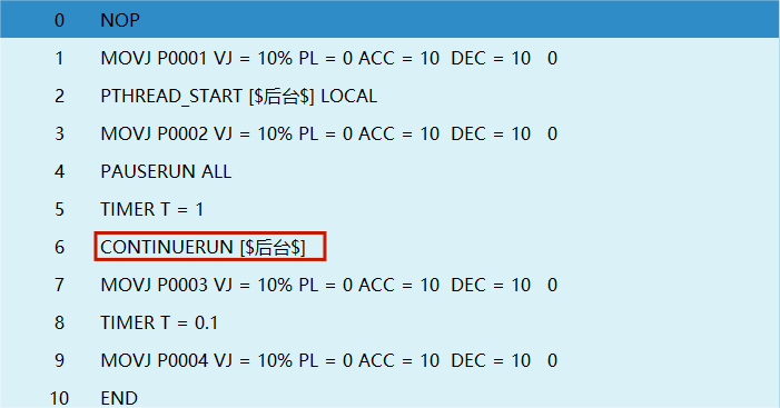
24.5 STOPRUN - Stop Run
Function: Stops all running programs.
24.6 RESTARTRUN - Restart Run
Function: Restarts a stopped program.
24.7 WINDOW - Popup Window
Function: Displays a popup window with the specified prompt content. The number of displayed buttons equals the number of options. The clicked button (option) value is saved to a local integer variable.
24.8 PTHREAD_STATE - Thread State
Function: The thread instruction can check the current state of the thread program. Stopped = 1, Paused = 2, Running = 3.
Usage example: PTHREAD_STATE [program filename] GINT GI001=0.
Q&A
Safety and Installation Related
Q: What are the environmental requirements for robot usage? A: The ambient temperature should be between -10C and 50C. Avoid direct sunlight, moisture, corrosive gases, and dusty/oily locations. Vibration should not exceed 0.6G.
Q: What are the requirements for control cabinet installation? A: The control cabinet should be installed outside the robot motion range (outside the safety fence), at least 500mm from the wall, vertically on a flame-retardant surface, with sufficient heat dissipation space.
Q: What are the cable wiring requirements? A: Cables of different levels should be routed separately, with at least 100mm spacing when running in parallel over long distances, and 90-degree crossings. Use symmetrically shielded cables and twisted pair shielded cables.
Teach Pendant Operation Related
Q: How to switch between teach mode, run mode, and remote mode? A: Use the mode selection key in the upper right corner of the teach pendant: left is teach mode, middle is run mode, right is remote mode.
Q: What is the Deadman switch function? A: Three-position switch. Press to middle to power on the robot, press to bottom to power off, release to power off.
Q: How to perform jog operation? A: In teach mode, press [Servo] to switch to ready, hold [DEADMAN] button, use right-side physical buttons (X+/X-, Y+/Y-, Z+/Z-, etc.) to control robot movement.
Coordinate System Related
Q: What coordinate systems are available? How to switch? A: Four coordinate systems: joint, Cartesian, tool, user. Press [Coordinate] button to cycle through, or click the coordinate system field in the status bar to select.
Q: What are the differences between joint, Cartesian, tool, and user coordinate systems? A: Joint controls each joint independently; Cartesian moves parallel to base XYZ axes; tool uses tool tip as origin; user can be defined at any position.
Programming Related
Q: How to create a new program? A: Enter [Project], click [New], enter program name (starting with letter or Chinese character), click [OK].
Q: How to insert motion instructions (MOVJ, MOVL, etc.)? A: In the program instruction interface, select the instruction line, click [Insert], select "Motion Control", choose the instruction (e.g., MOVJ point-to-point), set parameters, and confirm.
Q: What is the difference between MOVJ and MOVL? A: MOVJ (point-to-point) uses joint interpolation, path is not unique, speed is fast; MOVL (linear) uses linear interpolation, trajectory is a straight line, path is determined.
Tool Calibration Related
Q: How to perform 7-point tool calibration? A: Align tool end to fixed reference point, calibrate in 4 different postures (TC1-TC4), then calibrate TC5 vertically, based on this move in negative X direction to calibrate TC6, positive Y direction to calibrate TC7, finally click [Calculate].
Q: How to calibrate the user coordinate system? A: Move robot to desired user coordinate system origin, click "Calibrate Origin"; move any distance in positive X direction, click "Calibrate X-Axis"; move any distance in positive Y direction, click "Calibrate Y-Axis".
Variable Related
Q: What is the difference between global and local variables? A: Global variables (GINT, GD001, etc.) can be used across all robots and programs; local variables (I001, D001, etc.) can only be used in the program where they are defined.
Q: How to modify variable values in a program? A: Use the SET instruction, e.g., SET GI001=10, SET GD001=5.5, SET GB001=1, etc.
Run Mode Related
Q: What is the difference between teach mode and run mode? A: Teach mode is used for programming, jogging, and parameter setting; run mode is used for automatic program execution.
Q: How to set program run count? A: In run mode, click the [Run Count] button in the lower left corner. Default is single run, can be set to loop run.
Q: What is single-step execution? How to use it? A: Single-step execution runs one instruction at a time. In teach mode, select the instruction line, hold the [DEADMAN] button, click the [Single-Step] button to execute the current line.