1 Digital Quantity Settings
Turn on the controller, enter the "Process" screen, and select "Spraying Process" - "Digital Quantity Settings". At this time, it cannot be modified. Click the "Modify" button before it can be edited. After modification, click Save, as shown below:
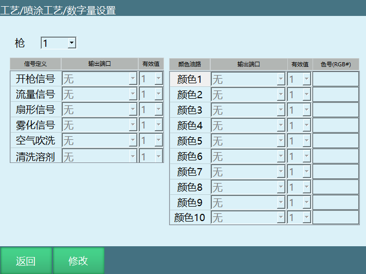
After clicking Modify, the Modify button changes to Save and the selection boxes turn white. At this point, the gun number can be selected, and the port, valid value and color number can be selected after each function. Use 16-bit RGB format for the color number. After filling in the color number, the corresponding "Color Oil Circuit" box changes to the corresponding color.
2 Analog Quantity Settings
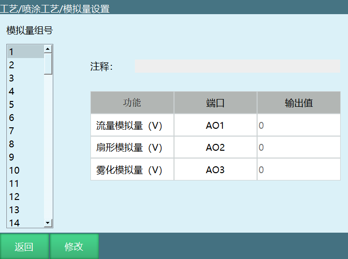
Select the group number to modify, and click the "Modify" button before the analog quantity group number can be modified and remarks filled in. A total of 99 groups of timing and their corresponding remarks can be set. Each group of timing includes the flow analog quantity, fan-shaped analog quantity and atomization analog quantity. This screen is for modification only; the corresponding instructions are required to invoke the relevant group number. After modification, click Save, as shown below:
3 Timing
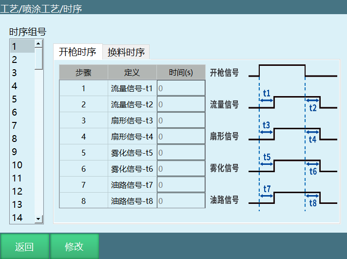
Select the group number to modify, and click the "Modify" button before the timing group number can be modified. A total of 99 groups of timing can be set. Each group of timing includes the gun-open timing and material-change timing. This screen is for modification only; the corresponding instructions are required to invoke the relevant group number. After modification, click Save, as shown:
3.1 Gun-Open Timing
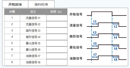
This is the timing when the gun opens. The times to be set for each signal on the left correspond to the timing diagram on the right. The flow, fan-shaped and atomization signals correspond to the ports set in the digital quantity settings; the oil circuit signal corresponds to the port set for the current color in the digital quantity settings, as shown below.
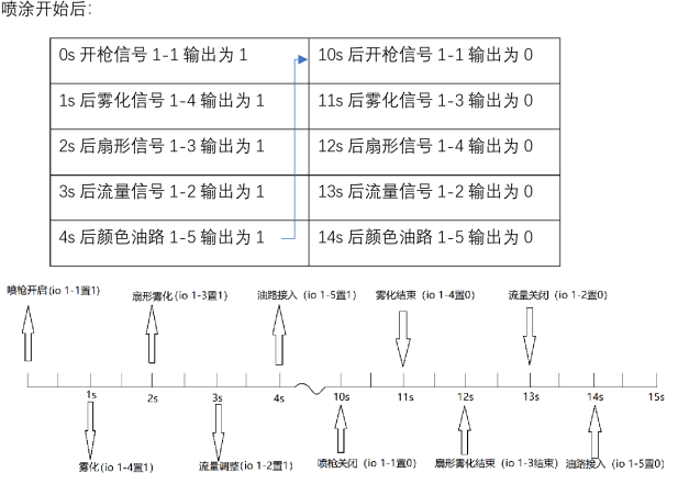
Example (for illustration only; set according to actual requirements): IO sets the gun-open signal to 1-1, flow signal 1-2, fan-shaped signal 1-3, atomization signal 1-4, color oil circuit 1-5. The spraying time is 10 s (i.e., the gun-open time is 10 s), t1=1, t2=1, t3=3, t4=3, t5=2, t6=2, t7=4, t8=4.
3.2 Material-Change Timing
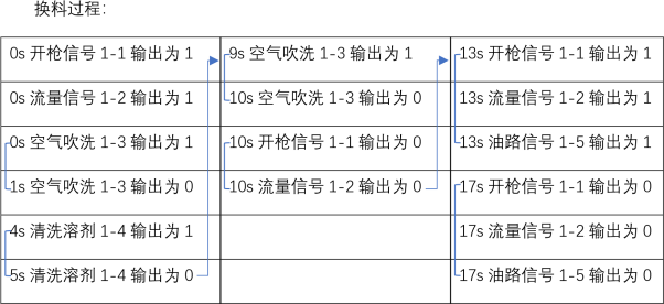
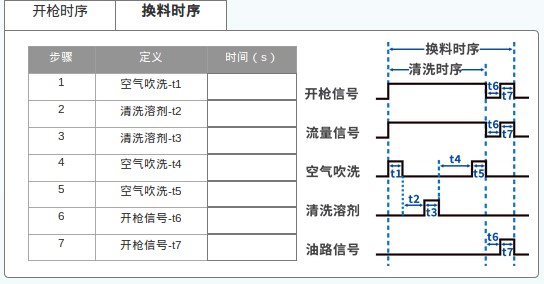
This is the timing during material change. The times to be set for each signal on the left correspond to the timing diagram on the right. The air blow, cleaning solvent and gun-open signals correspond to the ports set in the digital quantity settings. (As shown below)
Example: (The example is for illustration only; set according to actual requirements) The IO board sets the gun-open signal to 1-1, flow signal 1-2, air blow 1-3, cleaning solvent 1-4, color oil circuit 1-5. The gun-open signal is 10 s, t1=1, t2=3, t3=1, t4=4, t5=1, t6=3, t7=4.
4 Trajectory Parameters
A total of 99 trajectory group numbers can be set. Each trajectory group number includes trajectory type, trajectory kind, number of spray layers, number of additional passes, marked points. Click the "Modify" button before it can be set. After modification, click Save. (As shown below)
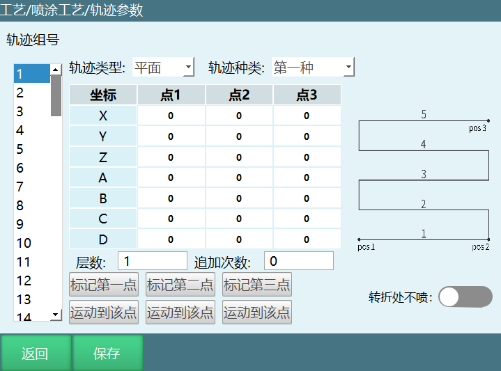
Trajectory type: Divided into plane, solid and custom, set as needed.
Trajectory kind: There are four kinds for plane and two kinds for solid, set as needed.
Number of layers: The number inside the red box in the figure below is the number of layers. Fill in a number to spray the corresponding number of layers.
Number of additional passes: The number of additional spraying passes per layer. For example, with 3 additional passes, each layer is sprayed back and forth 3 times before entering the next layer.
Marked points: The number of marked points corresponds to the points on the right side of the figure. Among them, the first/second kind of the plane type requires marking three points, and the third/fourth kind of the plane type and the first/second kind of the solid type require marking four points.
Example (for illustration only; set according to actual requirements):
With the number of layers set to 1 and 0 additional passes, the spray gun sprays from point A to point B;
With the number of layers set to 1 and 1 additional pass, the spray gun sprays from point A to point B and then back to point A;
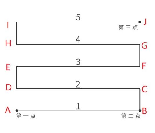
With the number of layers set to 2 and 1 additional pass, the spray gun runs through points A→B→A→D→C→D;
With the number of layers set to 3 and 3 additional passes, the spray gun runs through points A→B→A→B→C→D→C→D→E→F→E→F.
5 Manual Operation
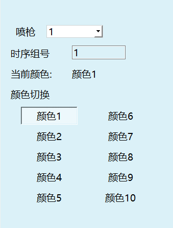
On the manual operation screen, the spray gun number and timing group number to be used can be selected. At the color switch, clicking the corresponding color changes the current color (the corresponding IO is set according to the timing - material-change timing). (As shown below)
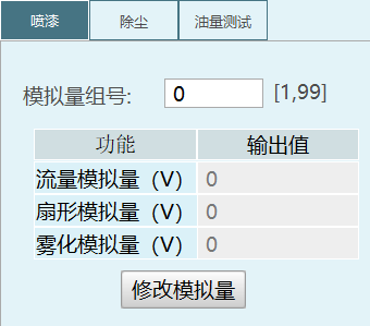
When the value of the "Analog Quantity Group No." input box is 0, the Modify Analog Quantities button is valid and clickable for manual modification. When it is not 0, the Modify Analog Quantities buttons in paint spraying, dust removal and oil quantity test are invalid and grayed out, and the three values below change to the values in the entered analog quantity group number. The analog quantities in paint spraying, dust removal and oil quantity test all use the 3 analog quantities set in paint spraying. As shown below:
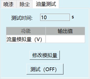
The Test button of the oil quantity test is OFF by default. After setting the test time, pressing it performs the oil quantity test for the corresponding time. At this time, the IO port of the current color oil circuit becomes a valid value. (As shown below)
Dust removal enable and paint spraying enable are OFF by default; pressing them switches to the ON state (as shown below).
Pressing dust removal enable sets the IO port corresponding to Air Blow in the digital quantity settings to a valid value; pressing paint spraying enable sets the corresponding IO ports according to the gun-open timing; pressing cleaning outputs the corresponding IO according to the cleaning timing.
Note: Color switch, dust removal enable, paint spraying enable, cleaning and oil quantity test are interlocked; only one function can be used at a time. For example, if paint spraying enable is ON and cleaning is pressed, spraying stops immediately and cleaning starts.
6 Spraying Instructions
6.1 SPRAY_ON - Start Spraying
The instruction marking the start of spraying. After running this instruction, the spraying process starts.
Function: Start of the spraying process.
Gun: Gun 1-2.
Timing group no.: Fill in the timing group.
Analog quantity group no.: Fill in the analog quantity group number.
Flow analog quantity, fan-shaped analog quantity, atomization analog quantity: Modify by filling in 0 for the analog quantity group number.
Example: SPRAY_ON G=1 T=1 AO=1
6.2 SPRAY_OFF - End Spraying
The instruction marking the end of spraying. After running this instruction, the spraying process ends.
Function: End of the spraying process.
Gun: Spray gun number 1-2.
Example: SPRAY_OFF G=1
6.3 SPRAY_CHANGE - Spraying Color Change
The instruction for changing the spray gun color. After running, the corresponding spray gun changes to the corresponding color according to the instruction parameters.
Function: Change color.
Gun: Spray gun number 1-2.
Timing group no.: Timing group number 1-99.
Color: Gun color number 1-10.
Example: SPRAY_CHANGE G=1 T=2 COLOR=1
6.4 SPRAY_MOVE - Spraying Trajectory
The spraying action instruction. Spraying is performed according to the set trajectory group number, speed, PL and acceleration.
Function: Move the robot according to the spraying trajectory.
Trajectory group no.: Trajectory group number 1-99.
Spraying speed: Speed 2-9999 mm/s.
Spraying PL: Smoothness 0-5.
Spraying acceleration: Acceleration 1-100%.
Spraying deceleration: Deceleration 1-100%.
Example: SPRAY_MOVE ID=1 V=10mm/s PL=0 ACC=1 DEC=1
6.5 SPRAY_POSE - Spraying Start Pose
Change the pose at the start of spraying. If this instruction is not used, spraying starts with the pose of the first calibrated point during spraying.
Function: Switch the robot pose.
Trajectory group no.: Trajectory group number 1-99.
Point state: Absolute marked point / pose only.
Speed: Pose-change speed.
Acceleration: Pose-change acceleration.
Deceleration: Pose-change deceleration.
TIME: Advance execution time.
Example: SPRAY_POSE ID=2 V=40mm/s ACC=4 DEC=4
6.6 Instruction Example
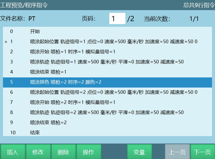
Description:
Move to the start point of the spraying trajectory;
Start invoking the spraying process parameters and open the spray gun;
Start the spraying trajectory movement;
End spraying and close the spray gun;
Switch spray gun / change spray gun color.
The following is the start of a new round of spraying trajectory, same as the previous flow.
Q&A
Q: What is the color number format in the digital quantity settings?
A: Use 16-bit RGB format for the color number. After filling it in, the corresponding "Color Oil Circuit" box automatically changes to the corresponding color.
Q: How many groups of analog quantities and timing can be set?
A: A total of 99 groups of analog quantities can be set, and a total of 99 groups of timing can also be set.
Q: What is the relationship between color switch, dust removal enable, paint spraying enable, cleaning and oil quantity test?
A: They are interlocked; only one function can be used at a time. For example, if cleaning is pressed while paint spraying enable is ON, spraying stops immediately and cleaning starts.
Q: How do I modify the digital quantity/analog quantity/timing settings?
A: After entering the corresponding screen, click the "Modify" button to edit, and after modification, click the "Save" button.
Q: What is the range of the spraying speed in the SPRAY_MOVE instruction?
A: The spraying speed range is 2-9999 mm/s.
Q: How many points do the plane type and the solid type need to be marked respectively in the trajectory parameters?
A: The first/second kind of the plane type requires marking three points, and the third/fourth kind of the plane type and the first/second kind of the solid type require marking four points.
Q: What is the difference in spray gun operation when the number of additional passes is 0 and 1?
A: With 0 additional passes, the spray gun sprays from point A to point B to complete one layer; with 1 additional pass, the spray gun sprays from point A to point B and then back to point A, i.e., one round trip.
Q: What is the difference in manual operation when the analog quantity group number is 0 and not 0?
A: When the analog quantity group number is 0, the analog quantity values can be modified manually; when it is not 0, the Modify Analog Quantities buttons in paint spraying, dust removal and oil quantity test are invalid and grayed out, and the three analog quantity values automatically change to the values in the entered group number.