1. Document Overview
1.1 Document Purpose
A detailed operation manual for robot welding process operation and programming personnel, mainly used to answer questions in welding-related process usage and provide programming examples.
1.2 Document Structure
Welder Setup: Analog welding and digital welder selection, digital welder manufacturer, communication method, and model selection
Welding IO: Setup of IO required for welding
Current/Voltage Matching: Analog welding current/voltage matching setup
Welding Parameters: Current/voltage parameter settings from arc start, welding, to arc end
Welding Equipment: Arc start, arc break, and collision prevention function settings
Weaving Parameters: Different weaving type parameter settings
Intersection Line: Intersection line workpiece calibration and setup
Manual Operation: Manual testing of welder current/voltage and manual welding current/voltage settings
Multi-layer Multi-pass Welding: Multi-layer multi-pass welding related offset settings and simple weld calculation
1.3 Terminology Definition
1.3.1 Welder and Control Method
Analog Control: Control welder output current/voltage through analog signals (e.g., 0-10V).
Digital Control: Control welder through digital communication protocols, supporting multiple fieldbuses.
CAN Communication: An industrial fieldbus.
ModBus RTU: Serial communication protocol based on RS485, commonly used in industrial equipment.
EtherCAT: Ethernet Control Automation Technology, real-time industrial Ethernet protocol.
ModBus TCP: ModBus protocol based on Ethernet.
Synergic Mode: Only need to set current, voltage automatically matched by welder.
Separate Mode: Current and voltage can be independently set.
Voltage Curve: Mapping relationship between welder output voltage and given signal (e.g., 10-50V or 0-50V).
1.3.2 IO Signals and Interfaces
Arc Start Success Signal: Digital input signal from welder feedback indicating arc start success.
Seek Position Success Signal: Feedback signal after welding wire touches workpiece, used for arc seeking.
Remote Welding Enable: Enable welding remotely through input signal.
Remote Wire Feed/Retract: Control wire feed or retract remotely through input signal.
Arc Start Signal: Digital output from system to welder, commanding to start arc.
Jog Wire Feed Signal: Output signal for manual wire feed control.
Reverse Wire Feed Signal: Output signal for controlling wire retract.
Gas Detection Signal: Signal controlling shielding gas output.
Seek Position Mode: Enable welder to enter seek position state, detecting wire contact with workpiece.
Welding Current/Voltage Signal: Analog input, collecting actual welder current/voltage.
Given Current/Voltage Signal: Analog output, current/voltage command sent to welder.
1.3.3 Welding Parameters and Process
Process Number: 1-99 numbers, corresponding to a set of welding parameters (e.g., different wire types).
Arc Start Current/Voltage: Current and voltage applied during arc initiation.
Arc Start Time: Time to maintain welding with arc start parameters after successful arc start.
Welding Current/Voltage: Current and voltage during normal welding.
Arc End Current/Voltage: Current and voltage gradually reduced to at welding end.
Arc End Time: Time to maintain welding with arc end parameters after reaching arc end point.
Gradient Enable: Allow current/voltage to smoothly transition from arc start value to welding value, or from welding value to arc end value.
Time Gradient: One of the gradient methods, linearly changing over set time.
Current/Voltage Matching: Calibrate the proportional relationship between analog output and actual welder output.
1.3.4 Welding Equipment and Auxiliary Functions
Multi-segment Matching: Fit current/voltage mapping curve in multiple segments (1-8 segments) for improved precision.
Arc Detection Time: Maximum time waiting for arc start success after sending arc start signal. Timeout triggers error.
Arc Detection Confirmation Time: Stable time for continuously detecting arc start success signal, preventing jitter.
Arc Exhaustion Detection Time: Allowed time from arc extinguish start to actual end. Timeout triggers error.
Delayed Gas Off Time: Time shielding gas continues output after welding ends, for cooling the welding gun.
Early Gas Off Time: Time to close gas before arc end.
Flying Arc Start: Robot starts arc while moving toward the welding start point.
Early Gas Delivery Time: Time to output shielding gas before arc start, preventing oxidation.
Restart: Function to automatically or manually resume welding after arc break.
Auto Restart: System automatically re-arcs and continues program after arc break.
Semi-auto Restart: Program pauses after arc break, manual click start to resume.
Stop (Restart Mode): Servo ready after arc break, program stops. Need to clear error and manual start.
Restart Distance: Distance welder retracts after arc break, for re-arcing.
Restart Speed: Speed of retract motion.
Re-arc: Retry arc start in place after arc start failure.
Re-arc Count: Maximum allowed retry count.
Collision Prevention: Detect welder collision through IO signal, trigger emergency stop.
Shield Collision Prevention: Temporarily close collision detection after collision, for moving welder away.
Welding Complete Retract: Auto retract wire after welding ends, preventing wire adhesion to workpiece.
Arc Break Retract: Auto retract wire when arc break occurs, preventing adhesion.
Arc Extinguish Analog Zero: Set analog output current/voltage signal to zero after welding ends.
1.3.5 Weaving Related
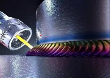
Weaving: Welding gun lateral oscillation during welding, increasing weld width.
Sine Weave: Oscillation trajectory is sine curve.
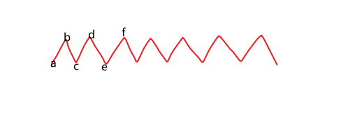
Z-shape Weave: Oscillation trajectory is Z-shaped polyline.
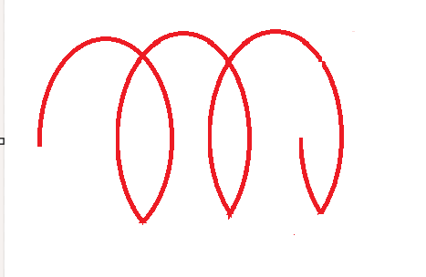
Circular Weave: Oscillation trajectory is circular.
External Axis Fixed-point Weave: Cooperate with external axis rotation, fixed-point oscillation on workpiece surface.
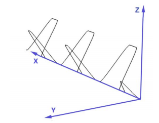
L-shape Weave: Oscillation trajectory is L-shaped, with left/right elevation angle parameters.
Triangle Weave: Oscillation trajectory is triangular.
Figure-8 Weave: Oscillation trajectory is figure-8 shaped.
Weave Amplitude: Oscillation width (peak to peak).
Weave Frequency: Number of oscillation cycles per unit time.
Start Direction: Direction at oscillation start (upward or downward).
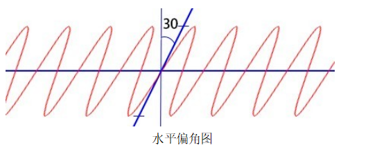
Horizontal Angle: Angle between oscillation plane and horizontal direction.
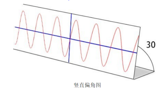
Vertical Angle: Angle between oscillation plane and vertical direction.
Left/Right Dwell Time: Dwell time when reaching left/right endpoints in Z-shape or fixed-point weave.
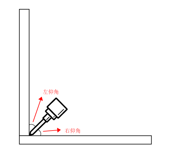
Left/Right Elevation Angle: Angle between left/right oscillation plane and tool Z-axis perpendicular plane in L-shape or triangle weave.
1.3.6 Special Welding Processes
Fish Scale Welding: An alternating welding and empty travel process, weld appearance is fish-scale shaped.
Spot Welding Time: Duration of each segment welding in fish scale welding (robot stationary welding).
Welding Distance (L1): Distance robot moves while continuously welding in fish scale welding.
Empty Travel Distance (L2): Distance robot moves without welding after arc extinguish in fish scale welding.
Intersection Line: Welding trajectory at the intersection of two cylinders or pipes.
1.3.7 Multi-layer Multi-pass Welding
Multi-layer Multi-pass Welding: For thick plate welding, a welding process requiring multiple layers with multiple weld passes per layer.
Process Number: 1-999 numbers, each process number can record a set of weld pass parameters.
Weld Pass Number: Up to 99 weld passes per process number, each with independent offset parameters.
Head Indent: Weld pass start point offset in welding reverse direction (positive) or welding direction (negative).
Tail Indent: Weld pass end point offset in welding direction (positive) or reverse direction (negative).
Left/Right Offset: Lateral offset of weld pass relative to reference trajectory, left positive, right negative.
Height Offset: Vertical offset of weld pass relative to reference trajectory, tool Z+ positive, Z- negative.
Push Angle: Vertical angle between tool and weld pass, welding direction positive, reverse direction negative (range -180° to 180°).
Tilt Angle: Horizontal angle between tool and weld pass, left tilt negative, right tilt positive (range -180° to 180°).
Welding Direction: Parameter ±1, only affects left/right offset and tilt angle sign, does not change actual robot motion direction.
Head Multiplier Indent Enable: When enabled, actual head indent = weld pass number × head indent value.
Tail Multiplier Indent Enable: When enabled, actual tail indent = weld pass number × tail indent value.
Tracking Path Data: Data number recorded during arc tracking, must match the record number in arc tracking instruction.
2. Core Content
Welder Configuration: Analog/digital control method, communication protocol, manufacturer selection.
IO Signal Definition: Arc start, seek position, wire feed, gas, current/voltage input/output.
Current/Voltage Matching: Multi-segment linear calibration.
Welding Parameters: Arc start/welding/arc end current, voltage, time, and gradient control.
Equipment Functions: Arc detection, restart/re-arc, collision prevention, retract, early/delayed gas delivery, etc.
Weaving Process: 7 weaving methods (sine, Z-shape, circular, L-shape, triangle, figure-8, external axis fixed-point), adjustable amplitude, frequency, angle, dwell time.
Multi-layer Multi-pass Welding: Process configuration: 1-999 process numbers, up to 99 weld passes per process number. Each weld pass can independently configure head/tail indent, left/right/height offset, push angle, tilt angle, welding direction, etc., with multiplier indent enable support.
Welding Instructions: ARCON/ARCOFF (arc start/end), WVON/WVOFF (weaving), FSWELDON/OFF (fish scale welding), SPOTWELD (spot welding), REFP (reference point), etc.
Practical Cases: Normal welding, weaving, fish scale welding, spot welding, external axis coordination, multi-machine coordination.
Welding Timing:
Welding Timing

2.1 Welder Setup
Welder setup needs to be modified in "Process/Welding Process/Welder Setup".
Steps:
Enter "Process/Welding Process/Welder Setup" page.
Two methods to control welder:
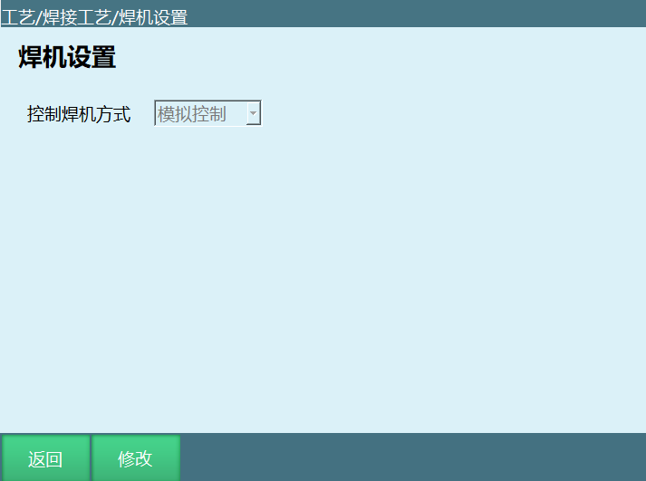
Analog Control: Full name analog welder, refers to welder controlled through IO analog. As shown below:
Digital Control: Set according to actual industrial site needs.
Click modify to select welder control method, as shown:
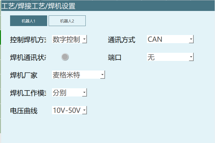
Four communication methods for digital welder: CAN, ModBus RTU, EtherCAT, ModBus TCP.
When selecting ModBus RTU, need to fill in slave ID, port number, baud rate;
When selecting ModBus TCP, need to fill in IP, port number.
Welding communication status: Gray means not connected, Green means connected.
Welding power manufacturer: Universal, Megmeet, Shenwei Intelligent, Aotai, Meijkenik, Ruiling, EWM.
Note: When selecting Ruiling, parameters need to be filled in [Material/Wire Diameter/Gas].
Welder working mode: Synergic mode, Separate mode.
Voltage Curve: When welder selects Megmeet, voltage curve can be selected, 10-50V or 0-50V.
Click save, save successful.
2.2 Welding IO Setup
Welding IO setup needs to be modified in "Process/Welding Process/Welding IO Setup". Related steps:
Enter "Process/Welding Process/Welding IO Setup" page.
After clicking modify, the modify button changes to save. Corresponding IO ports can be selected after each function.
2.2.1 Digital Input
Interface shown in figure:
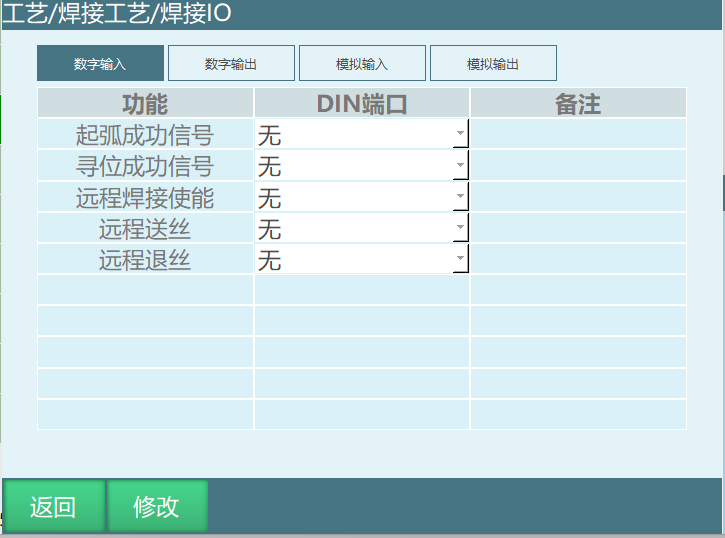
Parameter Description:
Arc Start Success Signal: Setting this signal is used to detect whether arc start was successful. When executing welding start instruction, arc start signal is needed. If arc start signal exceeds the set welding detection time, an error will be reported (welding arc start signal timeout).
Seek Position Success Signal: In arc seeking, seek position success signal needs to be set (required signal can select its own port).
Usage: In arc seeking, find two single-core wires. One wire's one end connects to IO output 1-5 (seek position mode signal), the other end connects to iron plate;
The other wire connects to IO input 1-6 (seek position success signal), the other end connects to tool hand end;
In arc seeking, open output 1-5. When tool hand end touches iron plate, the set 1-6 input signal changes from low to high level.
Remote Welding Enable: Setting this signal allows enabling welding through input signal.
Remote Wire Retract: Setting this signal allows wire retract through input signal.
Remote Wire Feed: Setting this signal allows wire feed through input signal.
2.1.2 Digital Output
Interface shown in figure:
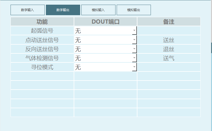
Parameter Description:
Arc Start Signal: When preparing to arc start, system sends output signal to welder.
Jog Wire Feed Signal: Welder wire feed. When corresponding signal port is open, welding monitoring window displays: Manual Operation - Wire Feed Switch Open.
Reverse Wire Feed Signal: IO board gives corresponding output signal when welder retracts wire.
Gas Detection Signal: IO board gives corresponding output signal when gas pump delivers gas.
Seek Position Mode: Represents welder entering seek position mode. When robot moves and wire touches workpiece, welder gives seek position success signal.
Usage: In arc seeking, find two single-core wires. One wire's one end connects to IO output 1-5 (seek position mode signal), the other end connects to iron plate.
The other wire connects to IO input 1-6 (seek position success signal), the other end connects to tool hand end.
In arc seeking, open output 1-5. When tool hand end touches iron plate, the set 1-6 input signal changes from low to high level.
2.1.3 Analog Input
Interface shown in figure:
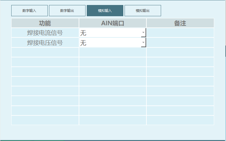
Welding Current Signal: Analog welder current input signal.
Welding Voltage Signal: Analog welder voltage input signal.
2.1.4 Analog Output
Interface shown in figure:
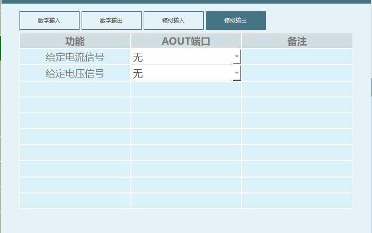
Given Current Signal: Given current signal.
Given Voltage Signal: Given voltage signal.
2.2 Current/Voltage Matching
Setting welding voltage/current needs to be modified in "Process/Welding Process/Current/Voltage Matching". Related steps:
Enter "Process/Welding Process/Current/Voltage Matching" page (Note: When digital welder is selected, this page is hidden).
At this time, current/voltage input boxes cannot input values. After clicking modify, the modify button changes to save. Values can be input after each parameter.
2.2.1 Current Control Matching Interface Parameter Setting Steps
Connect controller and welder, open teach pendant interface as shown:
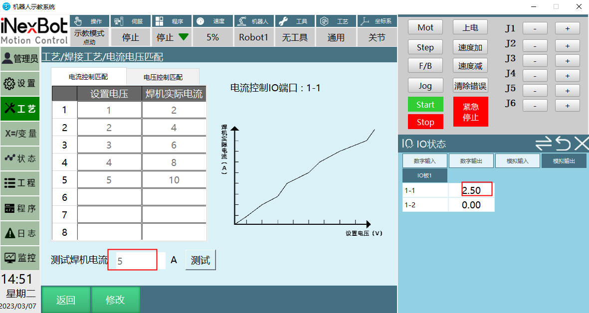
Set Voltage: Refers to analog output value in IO monitoring.
Welder Actual Current: Welder's actual output current, displayed on welder.
Test Welder Current: Fill in values in set voltage and welder actual current columns, input value in test welder current box, click test, a value will be calculated.
This value is calculated through the voltage and welder actual current values filled in the figure. The proportionality coefficient calculated from the values shown is 2.
At this time, test welder current is 5A. After clicking test, the selected analog output port calculates current value 2.5 through proportionality coefficient.
Note: Welder current AOUT port output upper limit is 10. When greater than 10, execute at upper limit. When welder current AOUT port lower limit is less than 0, execute at lower limit.
2.2.2 Voltage Control Matching Interface Parameter Setting Steps
Connect controller and welder, open teach pendant interface as shown:
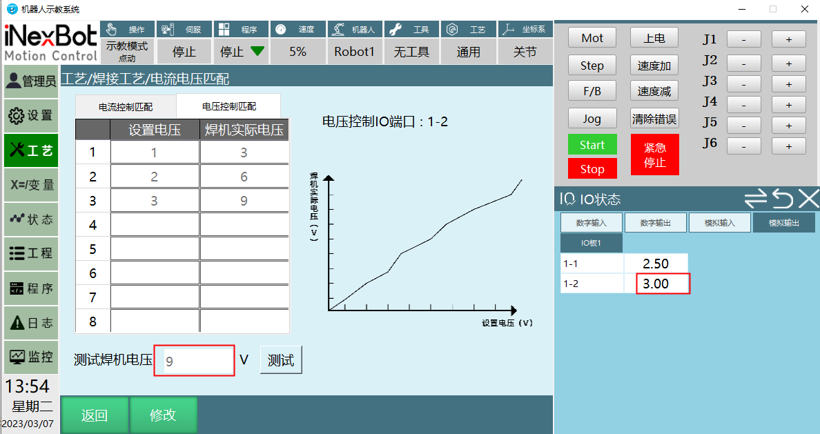
The function in the figure modifies the proportional relationship between controller-sent voltage/current and welder's actual voltage/current.
Set Voltage: Refers to analog output value in IO monitoring.
Welder Actual Voltage: Welder's actual output voltage, displayed on welder.
Test Welder Voltage: Fill in values in set voltage and welder actual voltage columns, input value in test welder voltage box, click test, a value will be calculated.
This value is calculated through the voltage and welder actual current values filled in the figure. The proportionality coefficient calculated from the values shown is 3.
At this time, test welder voltage is 9V. After clicking test, the selected analog output port calculates value 3 through proportionality coefficient.
Note: Welder voltage AOUT port output upper limit is 10. When greater than 10, execute at upper limit. When welder voltage AOUT port lower limit is less than 0, execute at lower limit.
2.2.3 Current/Voltage Matching Operation Steps When Connected to Welder
Current/voltage matching multi-segment matching: Current/voltage matching can be divided into multiple segments, 1-8 any number of segments.
Operation steps:
- Select current control matching.
- Row 1 set voltage fill 1, check welder's current value now, fill the seen current value in row 1 welder actual current;
- Row 2 set voltage fill 3, check welder's current value now, fill the seen current value in row 2 welder actual current;
- Repeat above operation until 8 rows are filled (if only 1 segment matching, fill rows 1 and 2);
- Test welder current fill 220, check if welder current is 220;
- Click save, modification successful. This function parameter saves 1 copy only, no process number.
2.3 Welding Parameter Setting
Setting welding parameters needs to be modified in "Process/Welding Process/Welding Parameter Setting". Related steps:
Enter "Process/Welding Process/Welding Parameter Setting" page;
Click modify, modify button changes to save. At this time, process number can be selected, arc start parameters, welding parameters, arc end parameters can be modified;
For example: If corresponding parameters need to be used, first open the corresponding enable.
If arc start current=10, arc start voltage=8, welding current=15, welding voltage=20, arc end current=10, arc end voltage=15.
Open arc start gradient enable, set arc start gradient time 1 second, arc start gradient method select [Time Gradient];
Open arc end gradient enable, set arc end gradient time 1 second, arc end gradient method select [Time Gradient].
Execution effect: After arc start signal, arc start current reaches 10A, arc start voltage 8V. Arc start gradient time set to 1 second, so within 1 second, current/voltage gradually changes from arc start current/voltage to welding current 15A, welding voltage 20V for welding. Arc end gradient set to 1 second, so within 1 second, current/voltage gradually changes from welding current/voltage to arc end current/voltage.
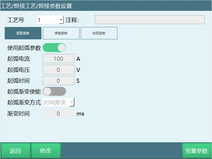
Process Number: Wire has multiple choices, carbon steel wire, low alloy structural steel wire, alloy structural steel wire, stainless steel wire, and non-ferrous metal wire. Different wires require different arc start voltage, arc start current, arc start time, welding voltage, welding current, arc extinguish voltage, arc extinguish current, arc extinguish time. Therefore, 1-99 different welding parameters can be set, and later only need to call.
Note: Comments can be added to this process number to indicate its purpose.
Use Arc Start Parameters: The parameters below will only take effect when this enable is opened.
Arc Start Current: Current applied when heating wire.
Arc Start Voltage: Voltage applied when heating wire.
Arc Start Time: Time to maintain welding with arc start current/voltage after confirming successful arc start;
For example, arc start current=20A, arc start voltage=10V, wait time is 1 second. This means maintaining welding with arc start current/voltage for 1 second after confirming successful arc start.
Arc Start Gradient Enable: Controls time from arc start current/voltage to welding current/voltage gradient.
Arc Start Gradient Method: Time gradient.
Gradient Time: Time from arc start current/voltage to welding current/voltage gradient;
Arc start gradient time set to 2 seconds. Within these 2 seconds, current/voltage will gradually change from arc start current/voltage to welding current/voltage, not directly reaching the set welding current/voltage.
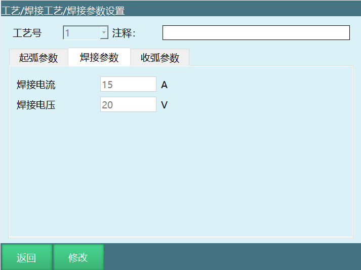
Welding Current: Current applied during welding. During welding, current flowing through the welding circuit is the balance result of wire feed speed and melting speed.
Welding Voltage: Welding voltage is arc voltage, providing welding energy and quality.
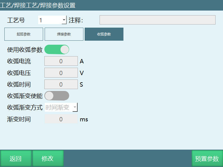
Use Arc End Parameters: The parameters below will only take effect when this enable is opened.
Arc End Current: Current given by arc extinguisher when arc needs to be extinguished during welding.
Arc End Voltage: The maximum power frequency voltage allowed to be applied to the arrester under the condition that the arrester can extinguish the arc at the first zero crossing of power frequency follow current. The arc extinguish voltage should be greater than the highest power frequency voltage that may appear on the arrester working bus, otherwise the arrester may explode due to inability to extinguish the arc.
Arc End Time: Time to maintain welding with arc end current/voltage after robot reaches arc extinguish point.
For example, arc end time is 1 second. This means maintaining welding with arc end current/voltage for 1 second after robot reaches arc extinguish point, then welding ends. Different arc extinguishing media have different arc extinguishing times, generally in seconds.
Arc End Gradient Enable: Controls time from welding current/voltage to arc end current/voltage gradient (Note: Gradient parameters below only take effect after gradient enable is opened).
Arc End Gradient Method: Time gradient.
Gradient Time: Time from welding current/voltage to arc end current/voltage gradient.
Set arc end gradient time to 2 seconds. Within 2 seconds, current/voltage will gradually change from welding current/voltage to arc end current/voltage, not directly changing from welding current/voltage to arc end current/voltage.
2.4 Welding Equipment Setting
Setting welding equipment needs to be modified in "Process/Welding Process/Welding Equipment Setting". Related steps:
Enter "Process/Welding Process/Welding Equipment Setting" page, as shown below.
Click "Modify", modify button changes to save. Click the selection box below to select the function you need.
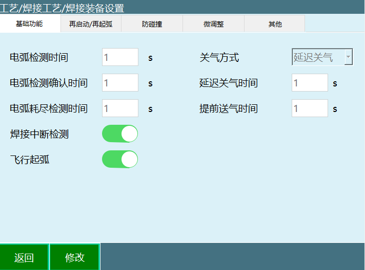
2.4.1 Basic Functions
Arc Detection Time: Time from sending arc start signal to system receiving welder's arc start success signal! If the system doesn't receive arc start success within this time, the system will report arc start signal timeout error (Note: Arc detection time must be greater than arc detection confirmation time).
Arc Detection Confirmation Time: To prevent dust or other obstacles from causing signal disruption, delay for a period to ensure arc signal transmission. During this time, if arc start success signal is continuously detected, welding begins.
Arc Exhaustion Detection Time: Time from arc extinguish start to actual arc extinguish end.
For example: Set arc exhaustion detection time to 2 seconds. This means the time from arc extinguish start to actual arc extinguish end is 2 seconds. After welding ends, if the arc start signal is still being given, arc extinguish failure will be reported.
Delayed Gas Off Time: After welding ends and arc extinguish signal is sent, the wire hasn't cooled yet. If gas delivery stops now, oxidation will still occur. Therefore, gas needs delayed shutoff, and it also has the function of cooling the welding gun.
Set delayed gas off 1s. After welding completes, in [Monitoring]-[IO Status-Digital Output] interface, you can see the set gas delivery signal will delay 1s before closing.
Early Gas Off Time: Time parameter for executing gas delivery end before arc end.
Set early gas off 1s. After welding completes, in [Monitoring]-[IO Status-Digital Output] interface, you can see the set gas delivery signal will close 1s early.
Flying Arc Start: Robot starts executing arc start while moving from safe point to welding start point, starting early gas delivery.
Early Gas Delivery Time: During welding, to prevent wire from being oxidized by air, early gas delivery may be needed to blow away air around the welding gun, reducing porosity in the weld, making the weld appear smoother.
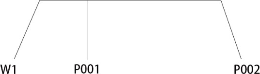
As shown above: W1 represents safe point, P001 represents welding start point, P002 represents welding end point, P001-P002 represents welding distance.
Open flying arc start.
When set gas delivery time is less than time from safe point to welding start point.
For example: Set early gas delivery time 4s. Robot needs 10s from W1 to welding start point P001.
Execution effect: W1 moves to P001 needs 10s. At 6th second, robot starts gas delivery. At 10s, reaches P001 point, simultaneously starts arc.
When set gas delivery time is greater than time from safe point to welding start point.
For example: Set early gas delivery time 4s. Robot needs 2s from W1 to welding start point P001.
Execution effect: W1 moves to P001 needs 2s. After moving to P001, robot will stay at P001 for 2s. At 4s, arc start will begin.
Close flying arc start.
Close flying arc start: After moving from safe point to welding start point, start early gas delivery.
For example: Close flying arc start, early gas delivery time 4S.
Execution effect: Robot moves from W1 point (safe point) to welding start point P001, then starts gas delivery. At 4s, robot starts arc.
2.4.2 Restart/Re-arc
Note: External axis instruction walking welding trajectory does not support restart retract.
Interface shown in figure. Restart mode is divided into auto restart, semi-auto restart, and stop.
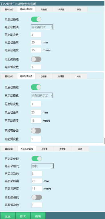
Interface parameter description:
Restart Enable: Restart enable. When arc break occurs, it is valid only when arc start signal is given.
Auto Restart: After detecting arc break, servo and program are both in running state. Within the set arc detection time, give arc start signal again, program continues running.
Semi-auto Restart: After detecting arc break, servo is in running state, program is in pause state. At this time, manual click start button is needed. Within the set arc detection time, give arc start signal again, program continues running.
Stop: After detecting arc break, servo is in ready state, program is in stop state. After arc break, error needs to be cleared, then manual click start button, give arc start signal.
Restart Distance: Distance for restart retract action.
Restart Speed: Speed for restart retract action. When speed is 0, no retract.
Re-arc Enable: First send signal for welder to arc start. If arc start fails, execute arc start action again in place. If arc start succeeds, execute welding normally. If still not successful within set number of times, stop and report error.
Re-arc Count: Maximum number of times to execute re-arc during current welder start to welding end interval. Exceeding will no longer execute restart.
Set re-arc count to 2 times. After arc break, if arc start signal is given more than 2 times without success, error will be reported.
Restart function (Note: Using this function requires opening welding interruption detection in basic functions)
Welding trajectory P001-P002. Welding start point P001, welding end point P002.
Auto restart. Restart distance 20mm. Restart speed 15mm/s.
Execution effect: After welding starts, robot moves from P001 to P002. After arc break, controller warns (welding arc break detected). At this time, servo and program are both in running state. Moving from P001 to P002, arc break occurs. Robot will move at 15mm/s for 20mm at the arc break point using your set restart distance and restart speed parameters. After reaching retract distance, give arc start signal again, robot executes welding operation again.
Semi-auto restart. Restart distance 20mm. Restart speed 15mm/s.
Execution effect: After welding starts, robot moves from P001 to P002. After arc break, controller warns (welding arc break detected). At this time, servo is in running state, program is in pause state, and there will be an arc break popup prompt. Moving from P001 to P002, arc break occurs. Click the popup prompt confirm button, then click start button. Robot will move at 15mm/s for 20mm at the arc break point using your set restart distance and restart speed parameters. After reaching retract distance, give arc start signal again, robot executes welding operation again.
Stop. Restart distance 20mm. Restart speed 15mm/s.
Execution effect: After welding starts, robot moves from P001 to P002. After arc break, controller errors (welding arc break detected). At this time, servo is in ready state, program is in stop state, and there will be an arc break popup prompt. Moving from P001 to P002, arc break occurs. After error, first click clear error button, then click popup prompt confirm button, then click start button. There will be another popup prompt (breakpoint execution, first line run). 1. Select breakpoint execution effect: Robot will move at 15mm/s for 20mm at the arc break point using your set restart distance and restart speed parameters. After reaching retract distance, give arc start signal again, robot executes welding operation again. 2. Select first line run effect: Robot will execute welding operation from the beginning.
Restart count.
When arc break occurs, the number of arc start signals that can be given. Execution effect: Set restart count to 3. After arc break, arc start signal can be given at most 3 times. When giving arc start signal the 4th time, controller will error (welding arc break detected).
2.4.3 Collision Prevention
Interface shown below:
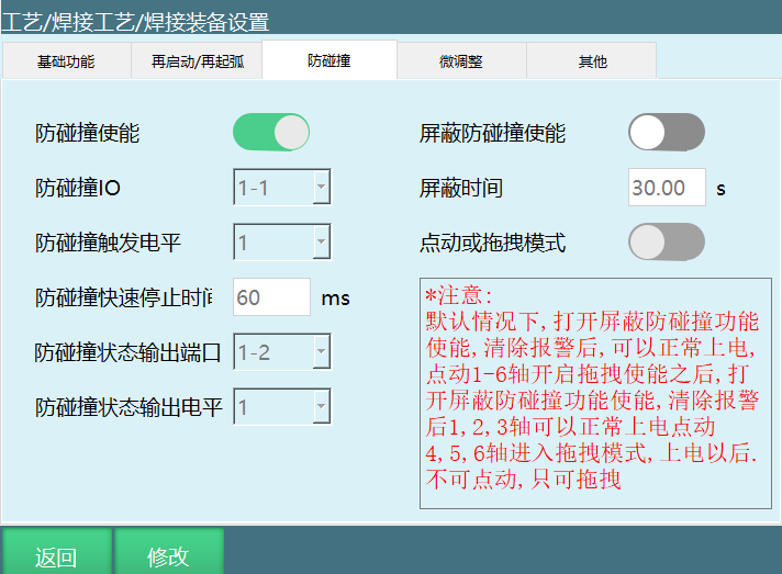
Interface parameter description:
Collision Prevention Enable: Open enable to detect collision prevention signal.
Collision Prevention IO: IO input signal when collision occurs.
Collision Prevention Trigger Level: 1-High level, 0-Low level.
Collision Prevention Quick Stop Time: Time from collision trigger to robot stop.
Set collision prevention quick stop time to 60ms. After collision, time from working to stop is 60ms.
Collision Prevention Status Output Port: Specified IO output port outputs signal when collision prevention is triggered.
Collision prevention status output level select 1. Set IO output port is 1-2. When collision occurs, output port 1-2 will change from low level 0 to high level 1.
Collision prevention status output level select 0. Set IO output port is 1-2. When collision occurs, output port 1-2 will change from high level 1 to low level 0.
Collision Prevention Status Output Level: 1-High level, 0-Low level.
Shield Collision Prevention Enable:
When welding gun collides, controller errors (welding gun collision prevention triggered).
At this time, cannot clear error. Need to open shield collision prevention enable, set shield time. During shield time, collision prevention signal is no longer detected.
If collision prevention signal is removed, shield collision prevention enable closes immediately.
Shield Time: Shield time parameter when collision occurs.
Open shield collision prevention enable, set shield time 10s. When collision occurs, shield for 10s, convenient for moving welding gun to safe position.
After reaching shield time, controller errors (shield ended, welding gun collision prevention triggered).
Jog or Drag Mode:
After collision, open shield collision prevention enable, set shield time.
Open jog or drag mode enable. After collision, can drag axes 4, 5, 6 (at this time, axes 4, 5, 6 can only be dragged, axes 1, 2, 3 can be jogged).
2.4.4 Fine Tuning
Interface shown below:
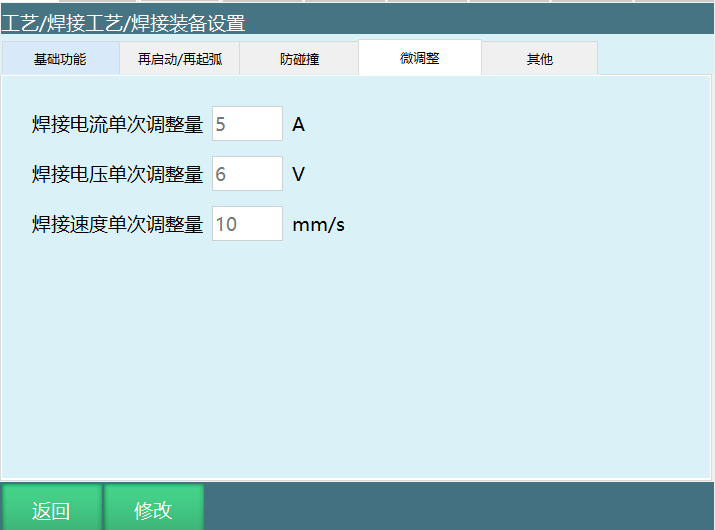
Interface parameter description:
Welding Current Single Adjustment: Single adjustment amplitude of welding current during welding.
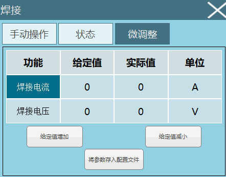
For example: Welding current single adjustment is 5A. During welding, if you want to increase or decrease current value, click Process Bar - [Welding Process] - [Fine Tuning].
Click given value increase, current value will increase 5A during welding. Click given value decrease, current value will decrease 5A (Note: Increase or decrease value is based on set welding current single adjustment).
Welding Voltage Single Adjustment: Single adjustment amplitude of welding voltage during welding.
For example: Welding voltage single adjustment is 6V. During welding, if you want to increase or decrease voltage value, click Process Bar - [Welding Process] - [Fine Tuning].
Click given value increase, voltage value will increase 6V during welding. Click given value decrease, current value will decrease 6V (Note: Increase or decrease value is based on set welding voltage single adjustment).
Welding Speed Single Adjustment: Welding equipment parameters can set fine tuning single adjustment amplitude.
2.4.5 Other
Interface shown below:
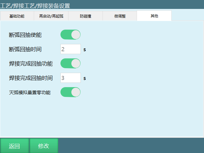
Interface parameter description:
Welding Complete Retract Function: At welding end, welding gun receives retract signal, wire retracts to prevent collision with workpiece when moving to next weld point.
Welding Complete Retract Time: Time to retract wire after completing welding.
Open welding complete retract enable, set complete retract time 3 seconds. After welding ends, total time from receiving retract signal to retract end is 3 seconds.
Arc Break Retract Enable: Welding current exceeds welder's rated duty cycle, welder has brief protection, arc break occurs. Wire needs to retract to prevent adhesion to workpiece.
Arc Break Retract Time: Time to retract wire after welding arc break.
Open arc break retract enable, set arc break retract time 2 seconds. To prevent wire adhesion to workpiece, wire retract time needs 2 seconds.
Arc Extinguish Analog Zero Function: After welding ends, analog voltage/current signal returns to zero (analog output).
2.5 Weaving Parameters
Weaving is a welding operation where the weld heat source performs regular lateral oscillation on the workpiece. Weaving effect shown below.
Setting weaving parameters needs to be modified in "Process/Welding Process/Weaving Parameters". Related steps:
Enter "Process/Welding Process/Weaving Parameters" page. Weaving file has 99 process numbers to choose from. Select the weaving parameters to modify, click the modify button at the bottom, all input boxes become editable;
After input, click save button to complete save.
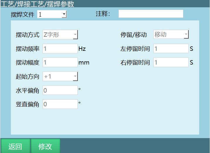
INEXBOT weaving supports seven weaving methods: Sine weave, Z-shape weave, Circular weave, External axis fixed-point weave, L-shape weave, Triangle weave, Figure-8 weave.
Weave frequency, weave amplitude, start direction, horizontal angle, vertical angle and other adjustable parameters can be set according to actual industrial site needs.
Weave Amplitude: Larger amplitude, larger robot oscillation.
Weave Frequency: Larger frequency, faster robot oscillation frequency.
Start Direction: +1, start from a point and move upward first; -1, start from a point and move downward first.
2.5.1 Sine Weave
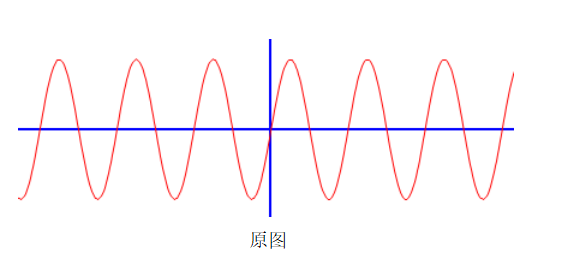
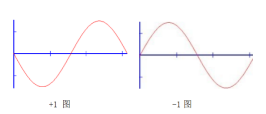
Horizontal Angle: Set horizontal angle 30° weaving trajectory, as shown below:
Vertical Angle: Set vertical angle 30° weaving trajectory, as shown:
2.5.2 Z-shape Weave
Move: Robot moves forward a set time each oscillation, then enters the next oscillation;
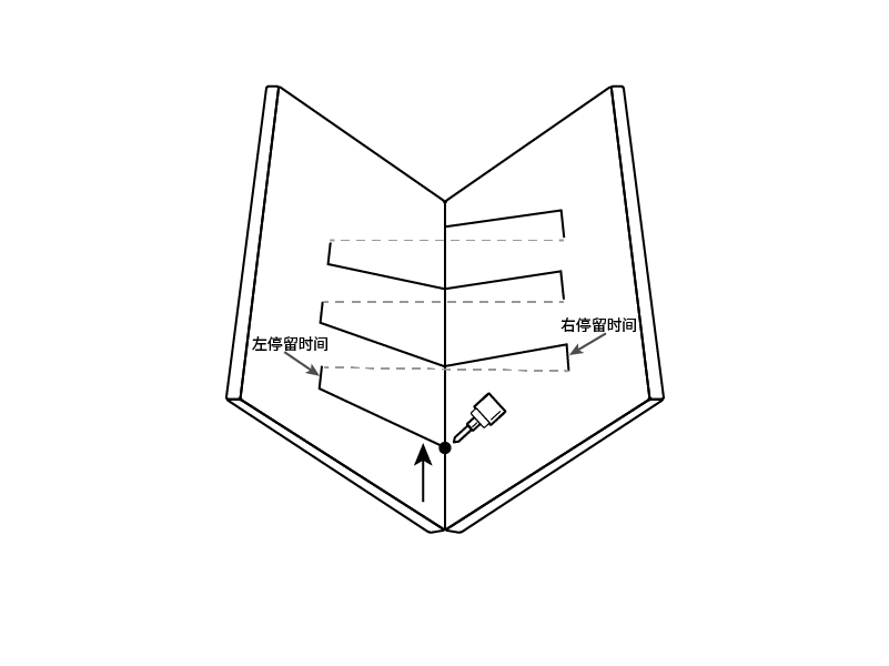
Left Dwell Time/Right Dwell Time: When weaving method is Z-shape weave, fixed-point weave will have left dwell time and right dwell time parameter settings; Indicates the time staying at a target point during Z-shape weave, fixed-point weave. As shown below;
Red trajectory represents Z-shape weave trajectory. If left and right dwell time set to 1 second, robot stays at point a for 1 second then moves to point b, then stays at point b for 1 second to point c. Following this logic until the entire weave trajectory is complete.
2.5.3 Circular Weave
Supports arc trajectory motion, optimizing the junction between two arc weaving segments for smoother connection.
Original circular weave trajectory and two-segment welding connection shown:
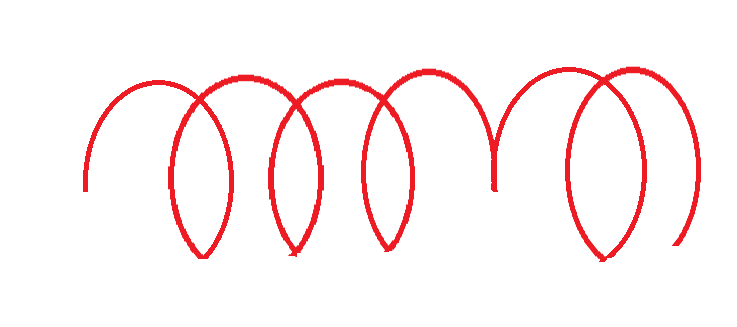
Current circular weave trajectory:
2.5.4 L-shape Weave
Trajectory diagram shown below:
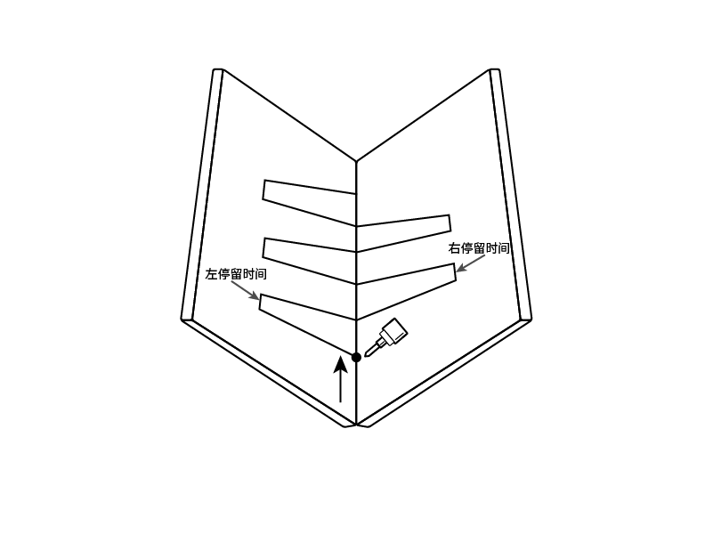
Parameters added on Z-shape weave: left elevation angle, right elevation angle.
Left/Right Elevation Angle: Angle between left/right oscillation plane and welding gun tool Z-axis direction perpendicular plane, as shown below:
2.5.5 Triangle Weave
Trajectory diagram shown below: