External Point TCP
How to use external points:
The tool is fixed externally, and the workpiece moves on the robot end-effector tool.
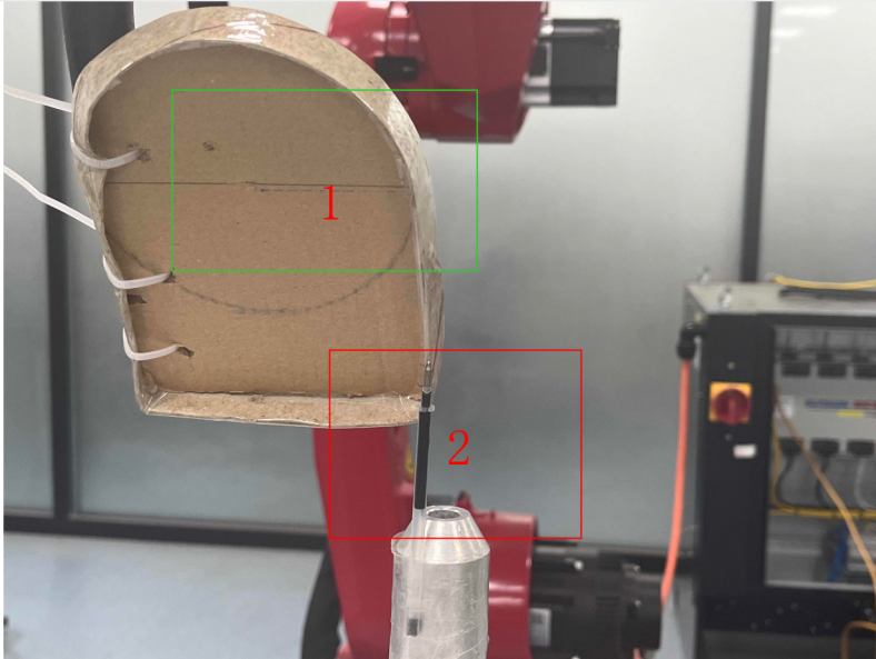
As shown in the figure: 1 represents the workpiece, 2 represents the external tool.
Calibration Steps:
1. Calibrate User Coordinate System:
Explanation: Find a point on the workpiece or install a calibration cone on the mechanical arm (just the tip). Align the point found on the workpiece or the calibration cone with the external tool tip, calibrate the user coordinate origin, then move the robot to mark X and Y. The postures of the user origin, X, and Y points must be the same.
External TCP means the workpiece is on the robot with the external tip fixed. Move the robot to calibrate the user coordinate on the tip. Our normal user coordinate calibration has the robot tip calibrated on the user plane. Now the tip is fixed and the user plane is on the robot. Move the robot to calibrate the user coordinate.
2. Select the calibrated user coordinate
3. Calibrate the tool (if the posture changes during runtime, tool calibration is needed)
The tool calibration method is the same as before. Each point on the workpiece and external point needs two points aligned for calibration.
Note: When calibrating the user and tool, the point on the workpiece must be the same point.
- Select the tool
Instruction Introduction
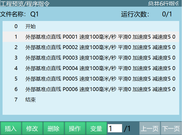
External Reference Point Linear
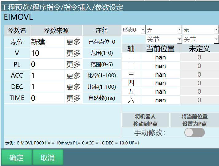
Program Writing
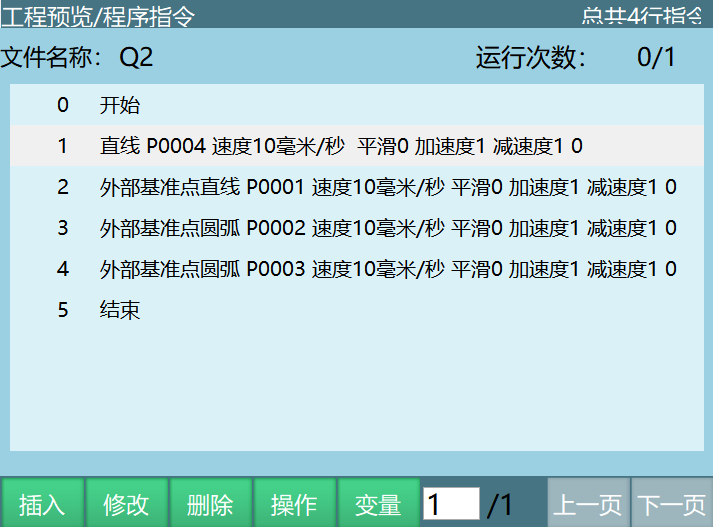
External Reference Point Arc
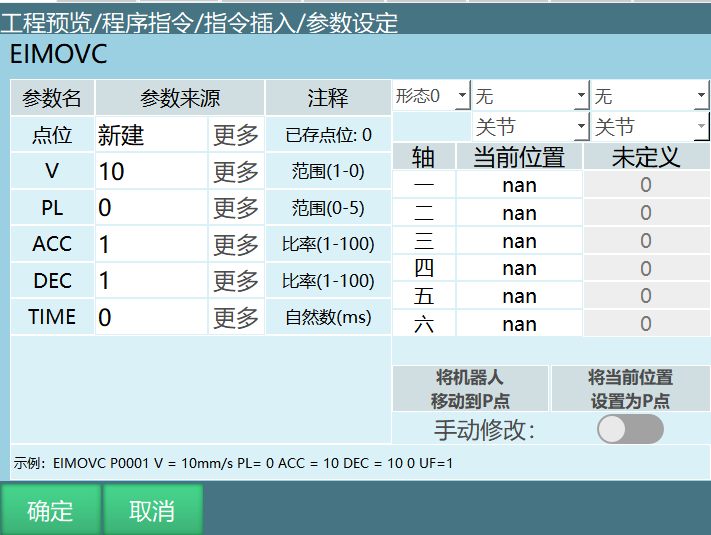
Program Writing
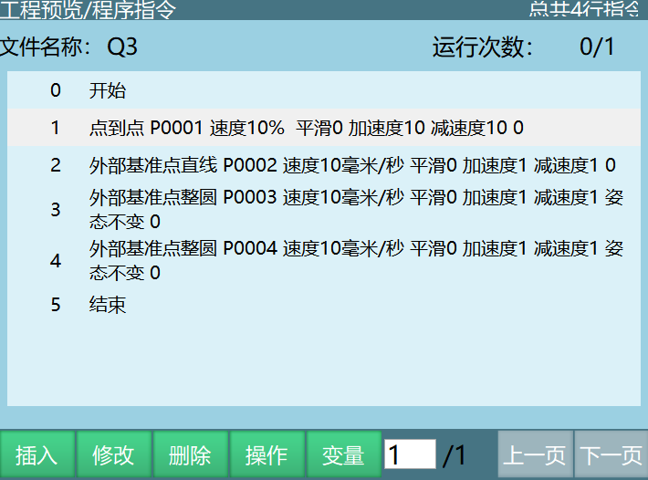
External Reference Point Full Circle
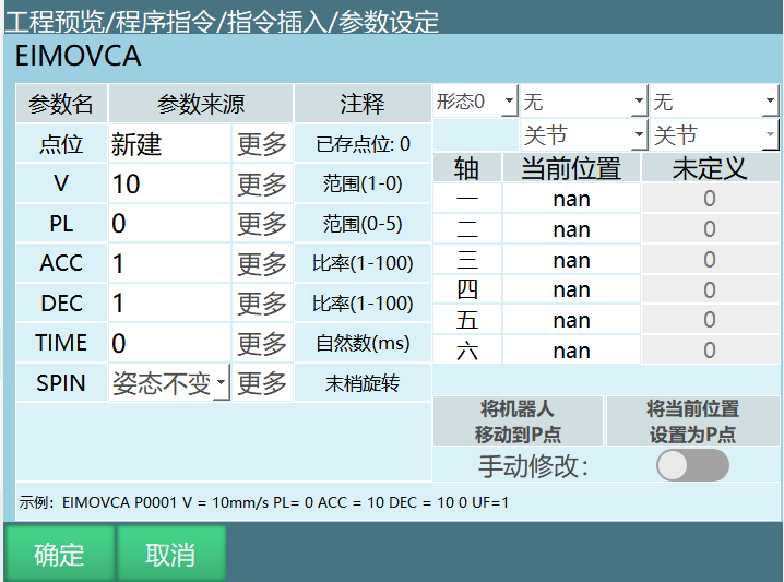
Program Writing
External Point TCP Effect Video
AI Retrieval Q&A (Q&A for Retrieval)
Q: What is the usage scenario of External Point TCP?
A: It is suitable for scenarios where the tool is fixed externally and the workpiece on the robot end-effector needs to move around the external tool, such as welding, cutting, and other processes.
Q: What should I pay attention to when calibrating the user coordinate system and tool?
A: When calibrating the user and tool, the point used on the workpiece must be the same point to ensure coordinate system consistency.
Q: How to test if the External Point TCP setting is correct?
A: Select a test line on the workpiece, teach 2 points (each point must be aligned with the external tool tip), insert EIMOVL instruction, and run a trial to see if the trajectory meets expectations.
Q: What impact does insufficient accuracy have on subsequent motion control?
A: Calibration accuracy directly affects the accuracy of subsequent motion trajectories. Insufficient accuracy will cause workpiece motion deviation, affecting process quality (such as welding position offset, cutting trajectory error, etc.).
Q: How to ensure the postures of user origin, X, and Y points are consistent?
A: During calibration, keep the robot end-effector tool posture unchanged and only move the position.
Q: When External Point TCP runtime shows deviation, how to troubleshoot and adjust?
A: 1. Check calibration accuracy: Re-execute the calibration process to ensure user coordinate system and tool calibration are accurate. 2. Check external tool: Confirm the external tool is securely fixed with no looseness or displacement. 3. Check instruction parameters: Verify the user coordinate system and tool selection in the instruction are correct. 4. Check robot status: Confirm all robot axes are running normally with no mechanical faults. 5. Adjust trajectory parameters: Fine-tune instruction parameters such as speed, acceleration, or trajectory points based on the deviation. 6. Use test program: Write a simple test program to troubleshoot the problem step by step. 7. Check environmental factors: Confirm whether environmental factors such as temperature and humidity affect system accuracy.
Q: What special attention is needed for External Point TCP related instruction parameter settings?
A: 1. User coordinate system selection: Ensure the correct calibrated user coordinate system is selected. 2. Tool selection: Select the calibrated external point tool. 3. Speed and acceleration: Set appropriate speed and acceleration based on workpiece mass and process requirements to avoid motion overshoot. 4. Trajectory type: Select linear, arc, or full circle instructions based on actual needs. 5. Pre-execution time: Adjust pre-execution time based on process requirements to ensure action coordination.
Related Resources
Version History
| Version | Date | Changes | Author |
|---|---|---|---|
| 1.0.0 | 2026-04-08 | Initial version | MUZI165 |