Tianji Seven-Axis CBCBCBA Custom Adaptation
Version Description
This adaptation currently only supports version 24.03 because the seven-axis model has only been adapted for version 24.03. The model adaptation process is consistent with normal adaptation.
End Communication Board Port Definition
Port Layout
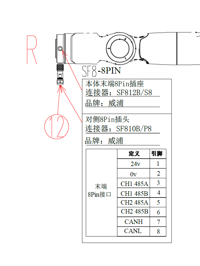
Port Function Description
Ports 1 and 2: Power Supply Ports
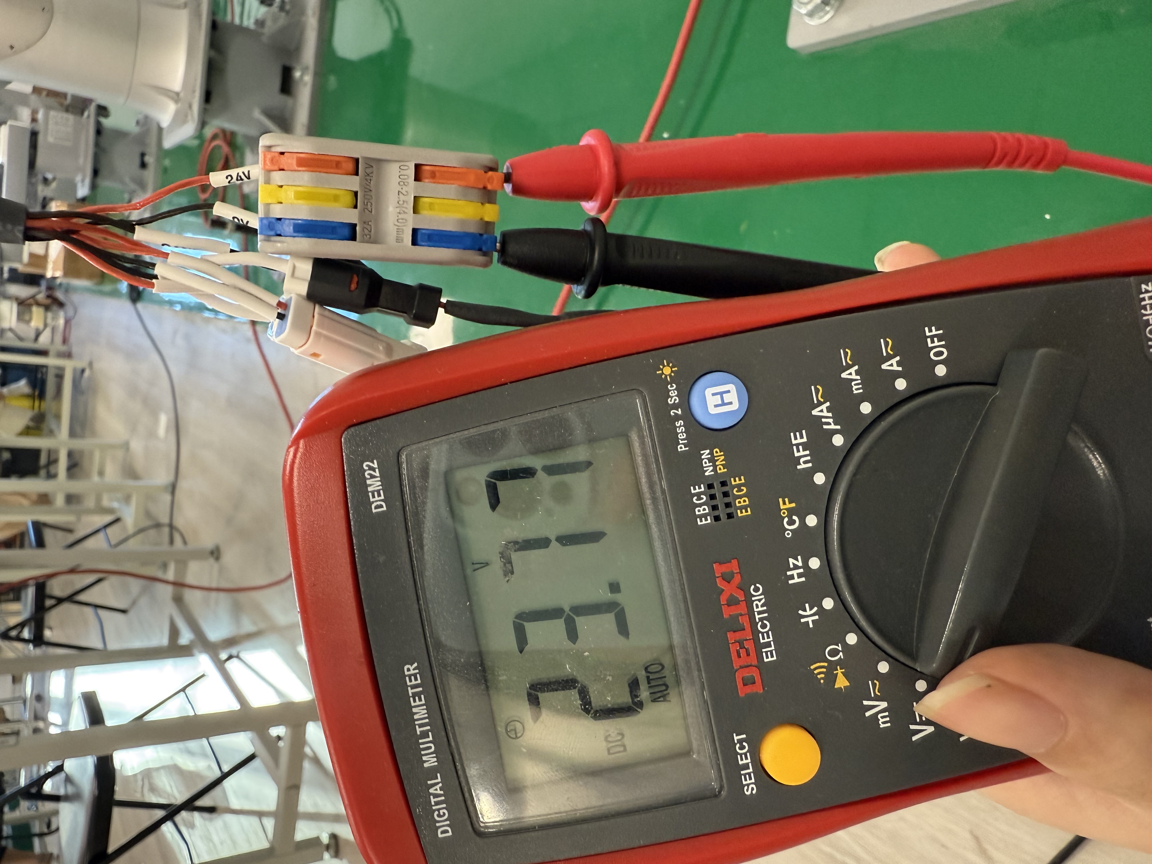
- End communication board - 8PIN_DC 24V interface validity check: Connect the 8Pin plug to the flange end, use a multimeter to measure the 24V output voltage. No node configuration required.
Ports 3 and 4: 485 1 Communication
- Note: 485 1 function cannot be used on older hardware versions (May).
- Currently has no complete functionality, only read/write forwarding operations are available.
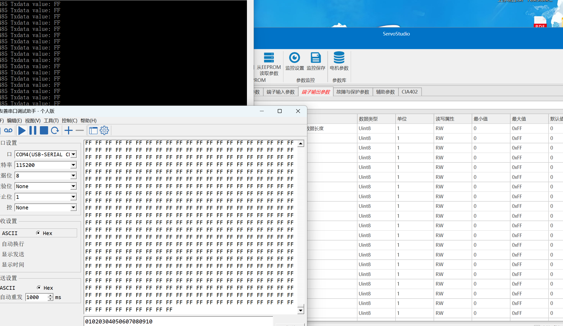
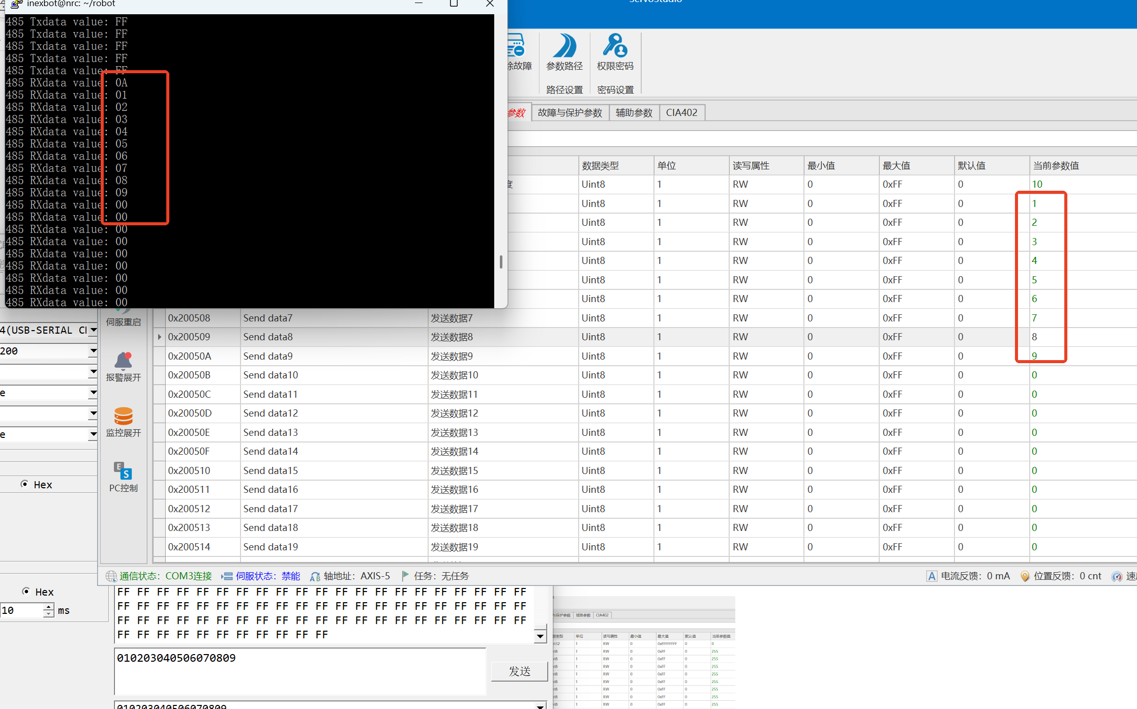
- Test result: Controller sends FF, host computer receives FF normally, serial simulator reads and writes normally.
Ports 4 and 5: 485 2 Communication
- Currently has no complete functionality, only read/write forwarding operations are available.
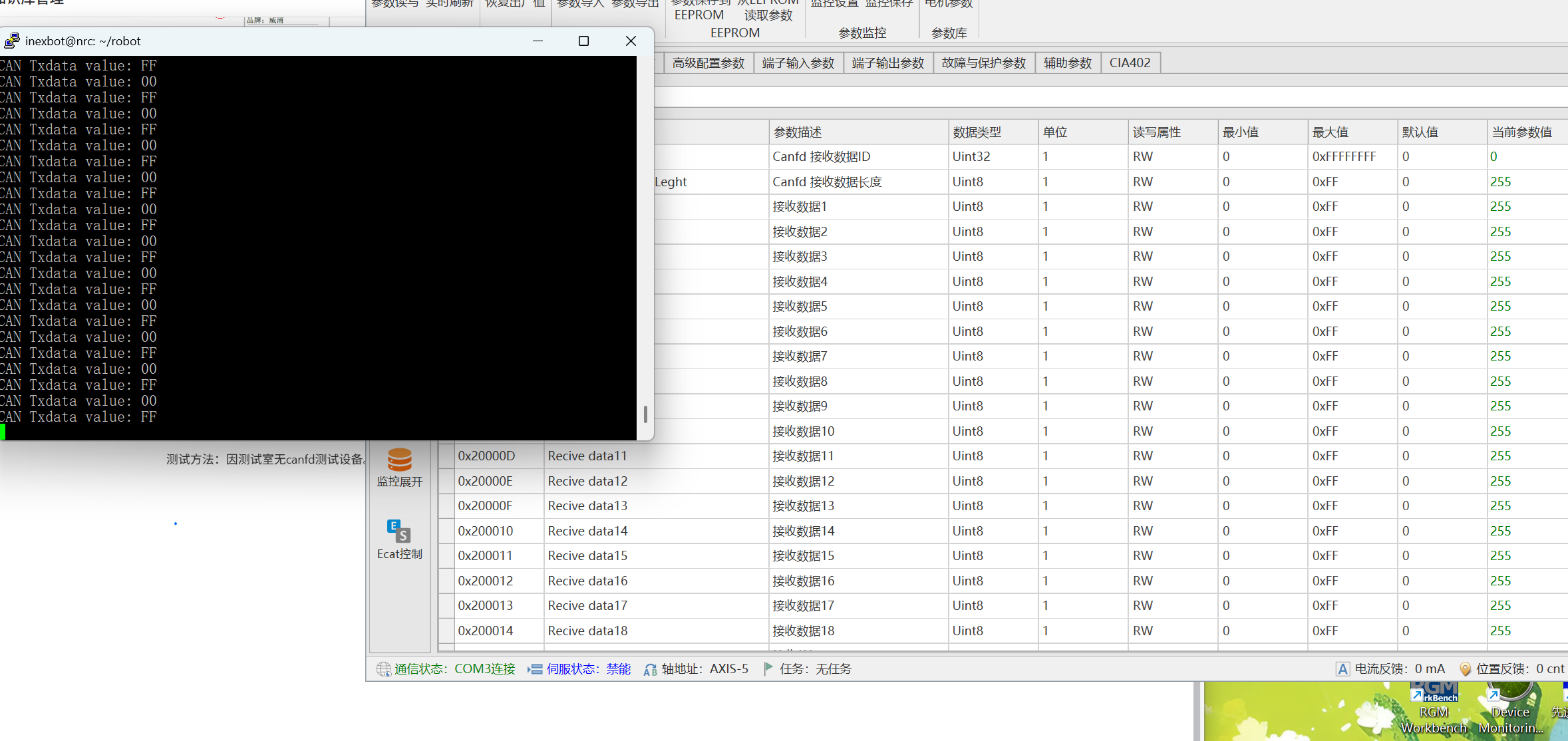
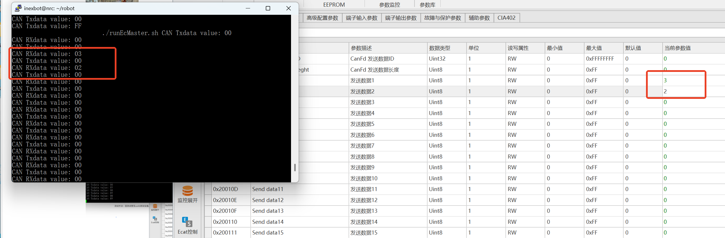
Ports 7 and 8: CAN FD Communication
- Currently has no complete functionality, only read/write forwarding operations are available.
- Test method: Use servo host communication testing or real CAN FD test equipment.
- Test result: Controller sends FF, host computer receives FF normally.
AI Retrieval Q&A (Q&A for Retrieval)
Q: Which versions does the Tianji seven-axis CBCBCBA adaptation support?
A: Currently only version 24.03 is supported. The seven-axis model has only been adapted for version 24.03.
Q: How are the end communication board ports defined?
A: The end communication board has 8 ports: Ports 1 and 2 are power supply ports (24V), Ports 3 and 4 are 485 1 communication, Ports 4 and 5 are 485 2 communication, Ports 7 and 8 are CAN FD communication.
Q: How to check if the end communication board power supply is normal?
A: Connect the 8Pin plug to the flange end and use a multimeter to measure the 24V output voltage. No node configuration is required.
Q: What are the limitations of the 485 1 communication function?
A: The 485 1 function cannot be used on older hardware versions (May). Currently 485 communication only has read/write forwarding functionality and is not yet complete.
Q: How to test CAN FD communication?
A: Since the test lab has no CAN FD test equipment, servo host communication testing is temporarily used. The test passes when the controller sends FF and the host computer receives FF normally.