IO Function User Manual
1 IO
1.1 Input/Output Instructions
1.1.1 DIN — Digital Input
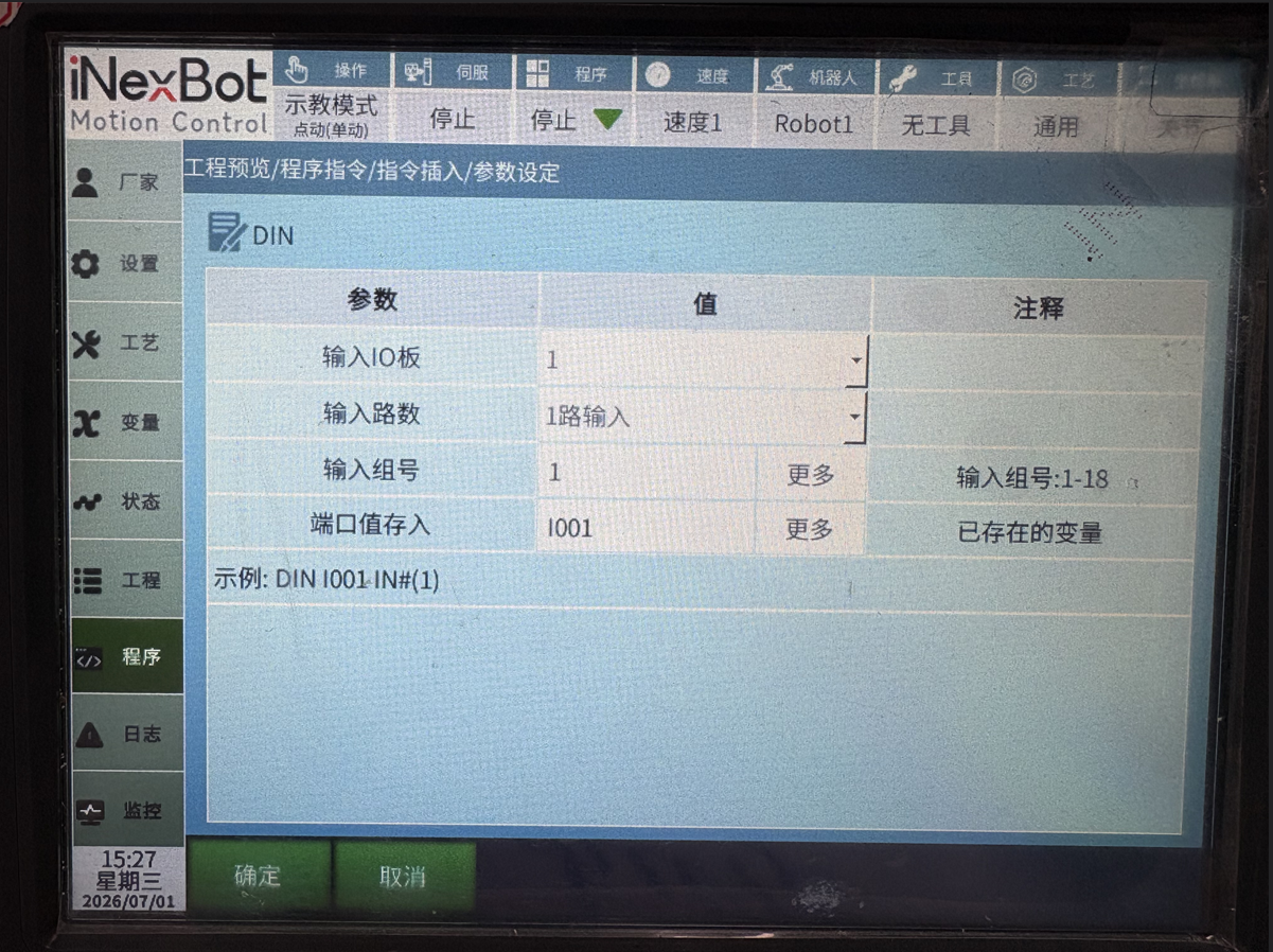
This instruction reads the digital input status into a variable. The variable can be a local integer variable, global integer variable (INT, GINT), or a local boolean variable, global boolean variable (B, GB).
Input IO Board: You can select IO board 1-4.
Input Channels: IN# — 1-channel input, where each channel is one group; groups 1-16 correspond to ports 1-16.
IGH# — 4-channel input, where every 4 channels form one group; ports 1-4, 5-8, 9-12, 13-16 are groups 1-4 respectively. The group number can be set to 1-4. For example, to read the input status of ports 5-8 simultaneously, set the group number to 2.
IG# — 8-channel input, where every 8 channels form one group; ports 1-8 are group 1, ports 9-16 are group 2. For example, to read the input status of ports 9-16 simultaneously, set the group number to 2.
When reading multiple channels simultaneously, the port status is converted from binary to decimal and stored in the variable. The group number can also be obtained from a corresponding variable.
For example, reading ports 5-8 with 4 channels, with the following statuses stored in I001:
| Port | 1 | 2 | 3 | 4 |
|---|---|---|---|---|
| Status | 0 | 1 | 1 | 0 |
The binary value is 0110, converted to decimal is 6.
The system stores: DIN I001 IGH#(1) 6.
For example, reading ports 9-16 with 8 channels, with the following statuses stored in GI001:
| Port | 16 | 15 | 14 | 13 | 12 | 11 | 10 | 9 |
|---|---|---|---|---|---|---|---|---|
| Status | 0 | 1 | 1 | 0 | 1 | 0 | 0 | 1 |
The binary value is 01101001, converted to decimal is 105.
The system stores: DIN GI001 IG#(2) 105.
Input Group Number: You can set to read 1/4/8 channels simultaneously, or use a bound variable value.
Store Port Value: Stores the IO input value into the selected variable.
1.1.2 DOUT — Digital Output
This instruction outputs digital signals through a digital IO board.
Output IO Board: Select the IO board to output, choices are 1-4.
Output Channels: OT# — 1-channel output, where each channel is one group; groups 1-18 correspond to ports 1-18.
OGH# — 4-channel output, where every 4 channels form one group; ports 1-4, 5-8, 9-12, 13-16 are groups 1-4 respectively. The group number can be set to 1-4. For example, to output to ports 5-8 simultaneously, set the group number to 2.
OG# — 8-channel output, where every 8 channels form one group; ports 1-8 are group 1, ports 9-16 are group 2. For example, to output to ports 9-16 simultaneously, set the group number to 2.
Output Group Number: You can set to output 1/4/8 channels simultaneously, or use a bound variable value.
Output Value: You can select manually or output via a variable, or use a bound variable value.
If manual selection is chosen, check each port's status in each IO group. Checked ports output 1, unchecked ports output 0.
If variable output is chosen, the variable value is converted from decimal to binary during output, similar to DIN.
Time: After instruction execution, waits for the specified time, then inverts the output.
Error Stop Handling: During IO signal output, if an error alarm occurs, the IO signal handles it differently.
Select Output Value Holds: While the program is running, if an alarm or other unexpected situation is triggered, the port output maintains its current state and the timer is paused. When the alarm is cleared and the program resumes normal operation, the IO output timer continues from the remaining time. When the timer expires, the port inverts.
Select Stop When Timer Ends: Regardless of the situation, once the port timer expires, the port value inverts, unaffected by pauses or errors.
1.1.3 AIN — Analog Input
This instruction reads the input value from a single port of the analog IO board into a variable.
Analog Input Port: Select the input port to read.
Variable Name: Select the variable name to read into, such as GD001.
1.1.4 AOUT — Analog Output
This instruction sets the output value of a single port on the analog IO board. The output value can be a floating-point number.
Analog Output Port: Select the output port to set the value for.
Variable Value Source: Select a global floating-point type GDOUBLE or local floating-point type DOUBLE variable, or enter a manual value.
1.1.5 PULSEOUT — Pulse Output
This instruction controls pulse output on IO boards that support PWM.
Count: Total number of pulse outputs.
Frequency: Pulse output frequency; for example, the default value of 100 means 100 pulses per second.
IO boards that support this function:
HUATAI IO PWM
INEXBOT R1 PWM
Usage:
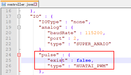
Modify the configuration file controller.json;
Find the "exist" parameter under "IO" > "pulse" and change it to true;
true: function enabled
false: function disabled
Find the "type" parameter under "IO" > "pulse" and change it to the corresponding IO board;
HUATAI_PWM: HUATAI IO
INEXBOT_PWM: INEXBOT R1
1.1.6 READ_DOUT — Read Output
This instruction reads the current digital IO board output status into a variable. Usage is the same as DIN, except it reads the output status.
2 IO Status Notification Settings
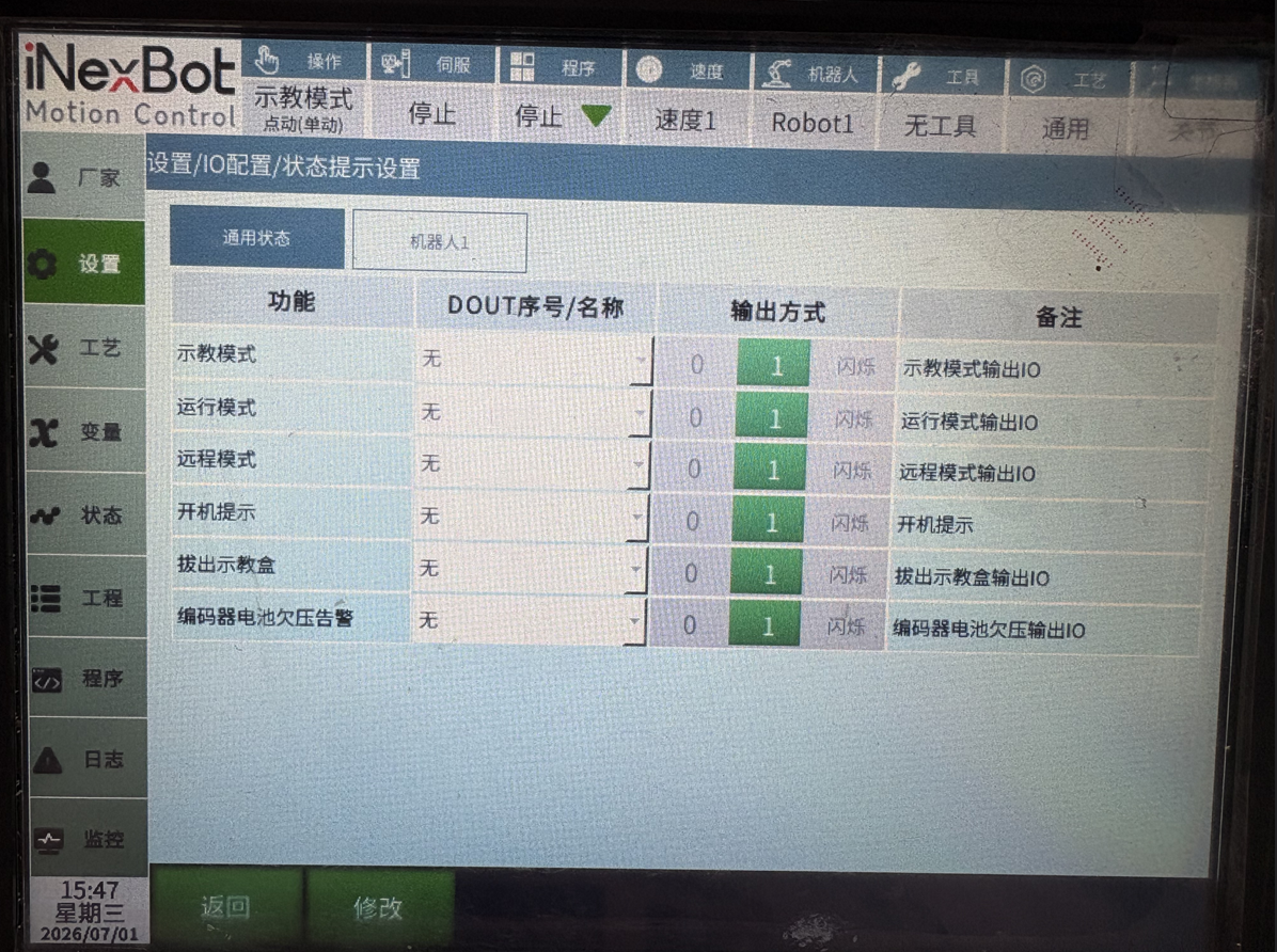
In the status notification settings interface, you can set the I/O ports and corresponding levels for functions such as power-on notification, robot running status, error notification, enable, mode status, and emergency stop.
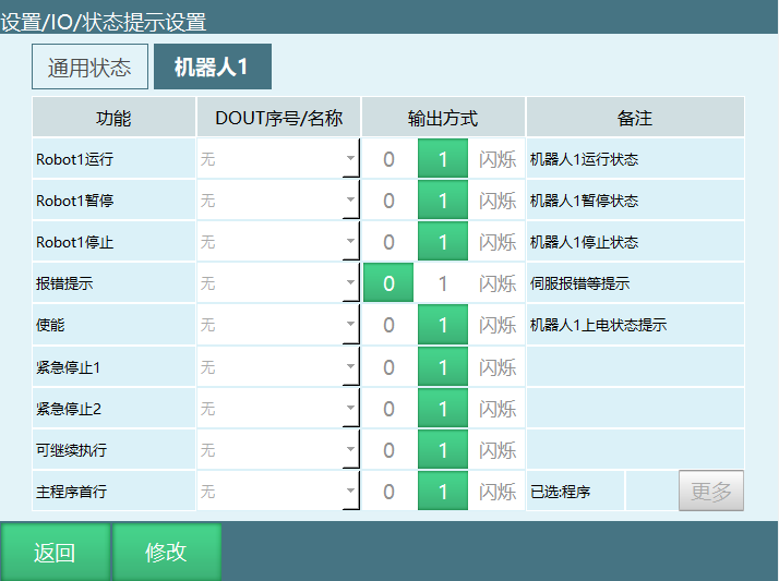
Robot1 Running: When robot 1 is running, the corresponding port outputs high/low level.
Robot1 Paused: When robot 1 is paused, the corresponding port outputs high/low level.
Robot1 Stopped: When robot 1 is stopped, the corresponding port outputs high/low level.
Error Notification: When the robot servo has an error, the corresponding port outputs high/low level. Can be set to steady on or blinking.
Enable: When the robot is powered on, the corresponding port outputs high/low level.
Emergency Stop 1: After the emergency stop signal is triggered, the corresponding port outputs high or low level. Can be set as desired.
Emergency Stop 2: After the emergency stop signal is triggered, the corresponding port outputs high or low level. Can be set as desired.
Main Program First Line: The corresponding port outputs a high-level signal with parameter 1, and the program cursor jumps to the first line of the main program.
Can Continue Execution: The corresponding port outputs a high-level signal with parameter 1, allowing paused programs to run.
Power-On Notification: Controller power-on output status; outputs high level on power-on.
Teach Mode: In teach mode, the corresponding port outputs high/low level.
Run Mode: In run mode, the corresponding port outputs high/low level.
Remote Mode: In remote mode, the corresponding port outputs high/low level.
Remove Teach Pendant: After removing the teach pendant, the corresponding port outputs high or low level. Can be set as desired.
3 IO Safety Settings
In the safety settings interface, you can set the I/O ports and corresponding levels for functions such as emergency stop and safety light curtain.
After the IO emergency stop is released, you must first click the clear error button to clear the error before performing other operations.
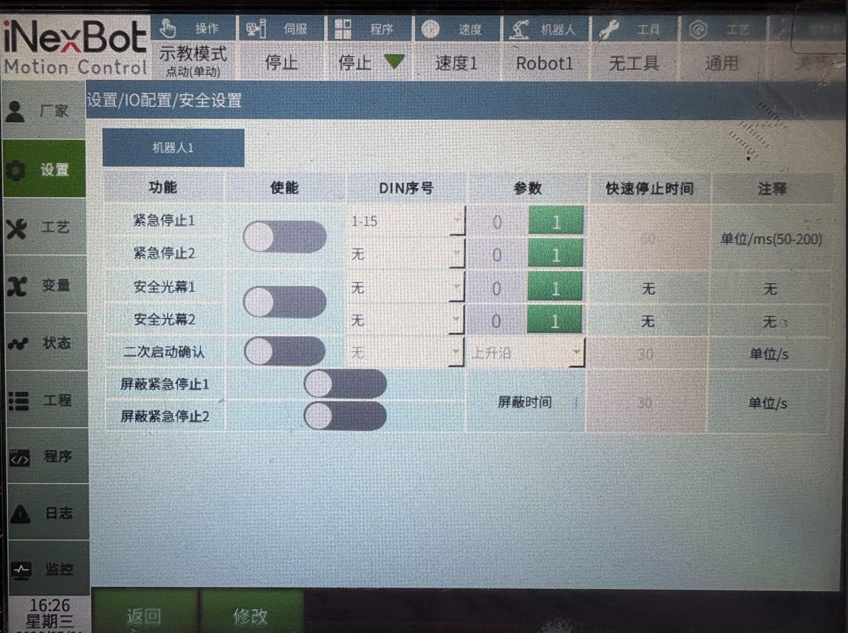
Emergency Stop: After the emergency stop signal is triggered, the robot powers off and switches to servo stop.
Safety Light Curtain: When the safety light curtain is triggered, the robot pauses. Press the start button again to continue running.
Mask Emergency Stop: When enabled, during the mask period, the emergency stop signal is masked.
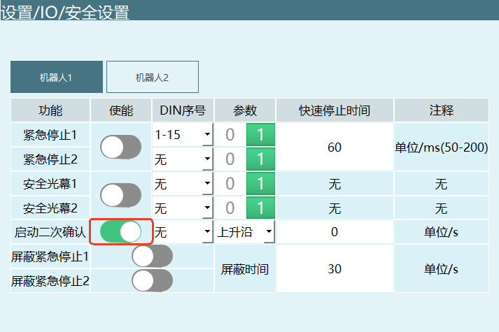
Secondary Start Confirmation: When enabled, after starting, the secondary start signal must be triggered before the robot can run.
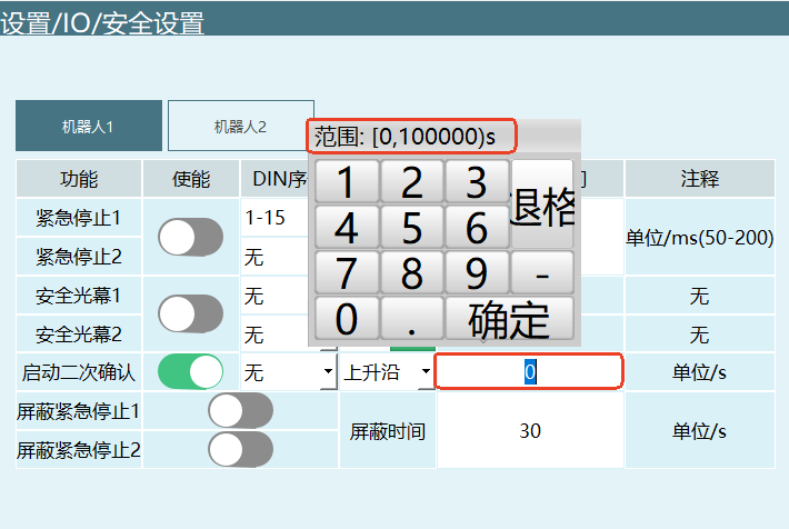
Click Settings > IO > Safety Settings, enable the secondary start confirmation.
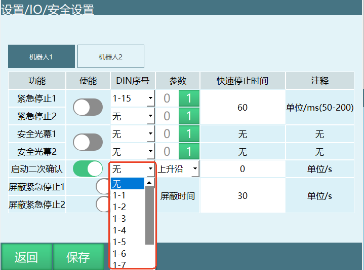
Select the corresponding DIN number.
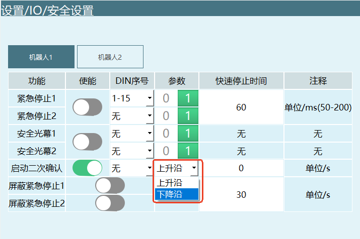
Select the trigger method (rising edge: 0→1, falling edge: 1→0).
Enter the secondary start confirmation time (range: [0-100000), unit: s). The secondary start confirmation time starts counting after the teach pendant start is triggered.
Notes:
In teach mode, whether the secondary start confirmation is enabled or not does not affect operation.
In run mode, if the secondary start confirmation is enabled, after clicking the start button on the teach pendant, you must also trigger the secondary start confirmation signal. The secondary start signal must be triggered within the set confirmation time, otherwise an alarm will be triggered.
In remote mode, if the secondary start confirmation is enabled, after triggering the start IO or using Modbus to trigger start, you must also trigger the secondary start confirmation signal. The secondary start signal must be triggered within the set confirmation time, otherwise an alarm will be triggered.
If the teach pendant start is triggered multiple times, the timeout is calculated from the first trigger time. After starting in remote or run mode, if the mode is changed, the secondary start confirmation time continues counting until timeout alarm or secondary start signal is triggered.
3.1 IO Reset
When the program stops running or has an error, the IO reset function can restore the IO output ports to their initial state. IO reset is divided into three types: IO reset, mode switch stop, and program error stop.
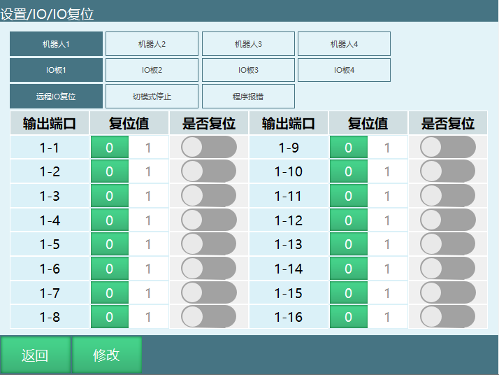
Remote IO Reset: In remote mode, when a reset signal is given and the robot executes the reset program to return to the reset point, the IO ports set in this interface are reset to the reset values. If the reset program stops midway, IO reset will not be performed.
Mode Switch Stop: When running a program, switching mode to teach or remote mode causes the program to stop, and the IO ports set in this interface are reset to the reset values.
Program Error Stop: When a program error causes the program to stop, the IO ports set in this interface are reset to the reset values. Specific error types: servo errors, IO setting errors, system runtime errors.
Usage Steps:
Enter the IO reset interface;
Select the robot;
Click to enter the reset scenario (IO reset, mode switch stop, program error stop);
Select the IO board;
Enable the "Reset" toggle for the IO ports that need to be reset;
Select the reset value (0/1), where 0 is low level and 1 is high level.
3.2 IO Configuration
The system automatically identifies IO models based on hardware connection order; no manual setting is required. This can be used to view the number and model of IO boards.
Enter [Settings] > [IO] > [IO Configuration].
The input fields are grayed out and values cannot be entered.
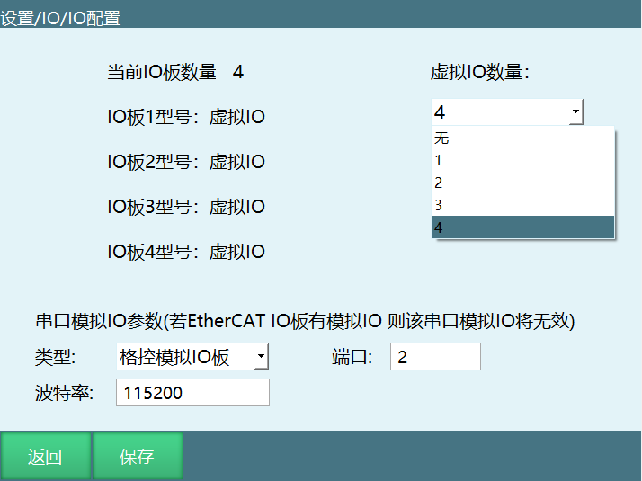
Click Modify; the Modify button changes to Save. Use the virtual IO board count dropdown to select the desired virtual IO.
Note: Virtual IO is only for program debugging and demonstration purposes; no actual IO signals are connected.
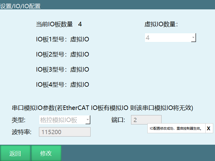
Click Save, restart to take effect. Modification successful.
3.3 Enable IO
If using a hardwired enable teach pendant, after connecting the cables, select the corresponding DIN port on this page and enable the enable toggle. The power-on enable function is then controlled by the IO board input signal. Do not set this for non-hardwired enable teach pendants.
After enabling this function, the teach pendant enable button becomes inactive and cannot be used.
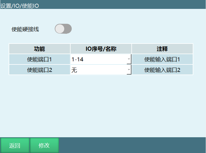
Enable port 1 is power-on enable, enable port 2 is power-off enable. Power-on only requires enabling port 1. In any case, as long as enable port 2 is opened, the robot will power off.
3.4 Alarm Messages
This function allows customizing alarm content for IO input/output ports. Alarm messages have higher priority than other types of IO alarm messages.
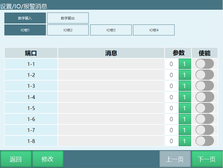
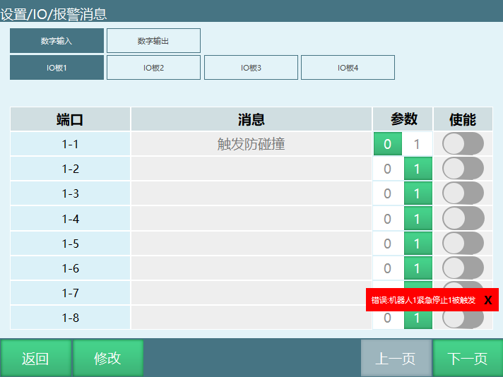
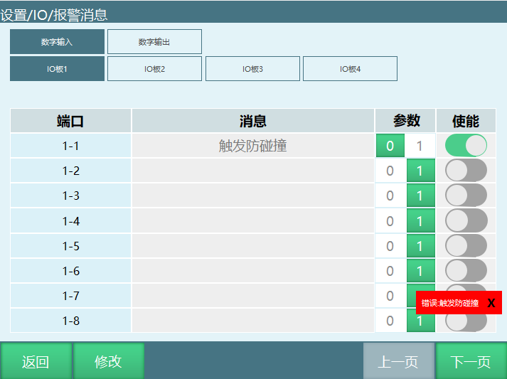
Example: Set the IO emergency stop signal port to 15 for anti-collision IO, with 1 triggering and 0 releasing. Triggering DIN1 reports "Robot 1 IO Emergency Stop Triggered". At this point, find DIN1 in the alarm message interface, enter "Anti-Collision Triggered" in the message field. Next time DIN15 is triggered, the error message will be "Anti-Collision Triggered" instead of "Robot 1 IO Emergency Stop Triggered".
3.5 Port Names
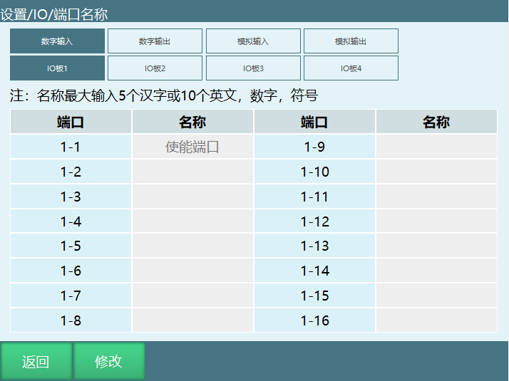
Port names support a maximum of 5 Chinese characters or 10 English characters. After successful setup, the name will automatically display when using IO port-related dropdown options.
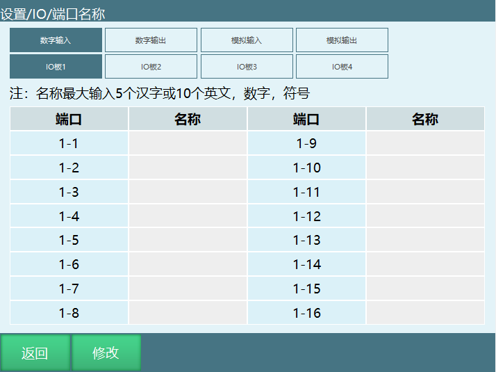
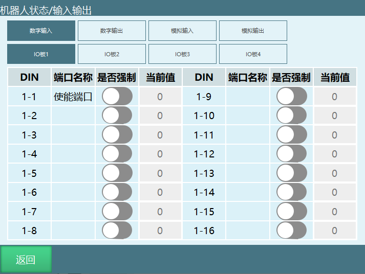
For example, if DIN1-1 is named "Enable Port", then in [Status] > [Input/Output], DIN1 will display the name "Enable Port".
4 Remote Mode IO Reservation Brief Description
Signal Description:
| Type | Function | Supported Mode | Trigger/Output Method | Description |
|---|---|---|---|---|
| Digital IO Input | Start | Remote Mode | Rising Edge | When parameter is 1, effective when signal changes from 0 to 1 |
| Digital IO Input | Stop | Remote Mode | Continuously Active | When parameter is 1, signal remains active |
| Digital IO Input | Pause | Remote Mode | Continuously Active | When parameter is 1, signal remains active |
| Digital IO Input | Clear Alarm | Remote Mode | Rising Edge | When parameter is 1, effective when signal changes from 0 to 1 |
| Digital IO Input | Reservation = Start | Remote Mode | None | When enabled, successful reservation immediately powers on |
| Digital IO Input | IO Remote Program 1-10 | Remote Mode | Pulse (period 0.6s) | When parameter is 1, effective on 0→1→0 signal; program reservation requires triggering for at least 0.6 seconds |
| Digital IO Input | Emergency Stop 1 | Teach, Run, Remote | High Level | Scanned every 1 ms; triggers immediately upon detection |
| Digital IO Input | Emergency Stop 2 | Teach, Run, Remote | High Level | - |
| Digital IO Input | Safety Light Curtain 1 | Run (running), Remote (running) | High Level | - |
| Digital IO Input | Safety Light Curtain 2 | Run (running), Remote (running) | High Level | - |
| Digital IO Input | Mask Emergency Stop 1 | Used with Emergency Stop | Button open masks emergency stop; rechecks after set time | - |
| Digital IO Input | Mask Emergency Stop 2 | Used with Emergency Stop | - | - |
| Digital IO Output | Power-On Notification | No Mode Limit | Steady/Blink, output only on power-on | Outputs high level |
| Digital IO Output | Robot1 Running | Teach, Run, Remote | Steady/Blink | Outputs high level when program is running |
| Digital IO Output | Robot1 Paused | Teach, Run, Remote | Steady/Blink | Outputs high level when program is paused |
| Digital IO Output | Robot1 Stopped | Teach, Run, Remote | Steady/Blink | Outputs high level when program is stopped |
| Digital IO Output | Error Notification | No Mode Limit | Steady/Blink | Steady outputs high level; blink outputs pulse (period 1s, 0.5s on, 0.5s off) |
| Digital IO Output | Enable | No Mode Limit | Steady/Blink | Outputs high level |
| Digital IO Output | IO Remote Program 1-10 Reservation Output | Remote Mode | Steady/Blink | Off when not reserved/reserved; blinks during reservation (period 1.2s, 0.6s on, 0.6s off); steady on when running, outputs high level |
| Digital IO Output | Emergency Stop 1 | Signal Triggered | High/Low/Blink | When parameter is 1, outputs high level |
| Digital IO Output | Emergency Stop 2 | Signal Triggered | - | - |
| Digital IO Output | Remove Teach Pendant | No Mode Limit | High/Low/Blink | Click remove teach pendant, outputs 1 or 0 |
| Digital IO Output | Can Continue Execution | Signal Triggered | High/Low/Blink | Outputs a high-level signal with parameter 1, allowing paused programs to run |
| Digital IO Output | Main Program First Line | Teach, Run, Remote | High/Low/Blink | Outputs a high-level signal with parameter 1; program cursor jumps to main program first line |
Note: This description uses output 1 as high-level output as an example.
4.1 Remote Mode Status Description
Not Reserved: After entering remote mode, no program has been reserved, or a reservation was cancelled. Displays as Not Reserved.
Reserving: After successful reservation. Displays as Reserving.
Running: When the program is running. Displays as Running.
Reserved: After program completion or when the program is triggered to stop. Displays as Reserved.
Remote mode cannot modify speed; speed changes must be made in advance in [Settings > Remote Program Settings].
Reserving a Program:
Triggering the corresponding program's IO port successfully reserves the program. To cancel, trigger the corresponding IO port again.
Start can be triggered directly by triggering the corresponding IO port.
Reservation = Start: Signal 0→1 (press button) for more than 0.6 seconds, then 1→0 (release button), and the program runs directly. When Reservation = Start is enabled, the start signal does not need to be set.
Reserved programs can be reserved again after running.
Troubleshooting:
After IO function settings are successful, go to Status > IO Function Status to verify the settings or check for conflicting functions.
Reset Point Settings:
The reset point function supports joint and linear motion to a safety point, or uses the reset program instruction to customize the reset trajectory and position.
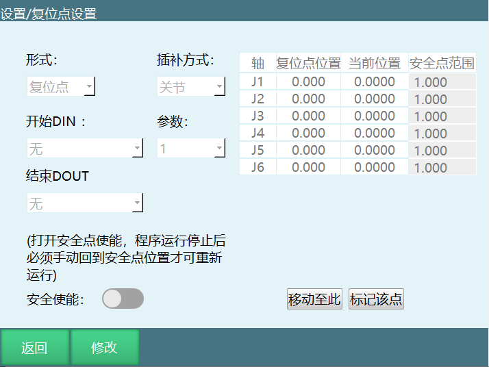
Form: Reset point, reset program.
Interpolation Method: Joint, linear. Joint interpolation speed is 10% of global speed; linear interpolation speed is 100 mm/s. Reset program speed equals instruction speed × status bar speed.
Safety Enable: When enabled, program execution checks whether the robot is at the reset (safety) point. The robot must be at the reset point to continue running the program.
Start DIN: Reset point trigger signal.
Parameter: Reset point trigger signal effective at 0 or 1.
End DOUT: Status signal output after returning to the reset point.
Safety Point Range: Safety range error for each axis. Within the range is judged to be at the reset (safety) point.
Mark This Point: Sets the current robot coordinates as the reset point. Click confirm to complete the setup.
Move To: Moves to the reset point using joint interpolation.
4.2 Remote Mode Control Authority Description
When the control system has a teach pendant, touchscreen, and I/O control device simultaneously, the control authority priority is: Teach Pendant > Touchscreen > I/O Control Device.
After switching to remote mode, control authority switches to the touchscreen. If no touchscreen is present, it switches to I/O control. The teach pendant interface only displays the Modbus module and I/O module connection status and I/O programs.
When both a touchscreen and I/O module are present, set the I/O module enable in the touchscreen.
4.3 Remote IO Control
4.3.1 Remote I/O Function Selection Settings
In "Remote Program Settings > Remote IO Function", you can set the I/O ports and corresponding levels for remote IO control functions such as start, stop, pause, emergency stop, and clear alarm. You can also set the programs that the I/O module remote control runs.
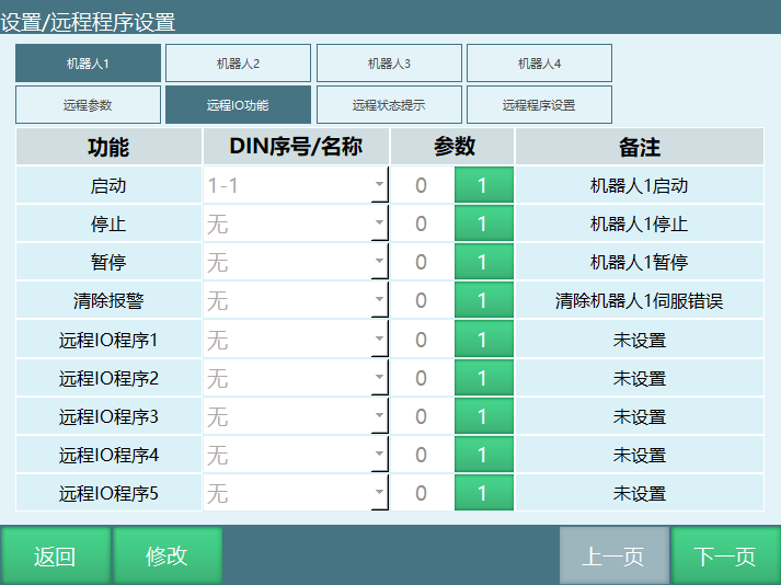
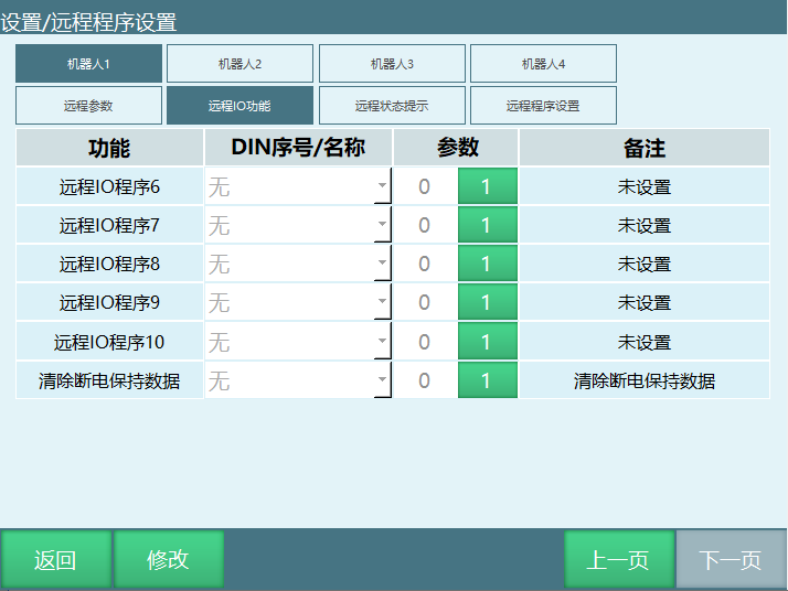
The programs set for the I/O module can only be selected from programs already configured in the "Remote Program Settings" interface.
Remote reservation supports up to 10 programs.
Reservation = Start: When enabled, the first reserved program immediately powers on and runs upon successful reservation. Other programs can be reserved at the same time.
4.3.2 Remote Program Settings
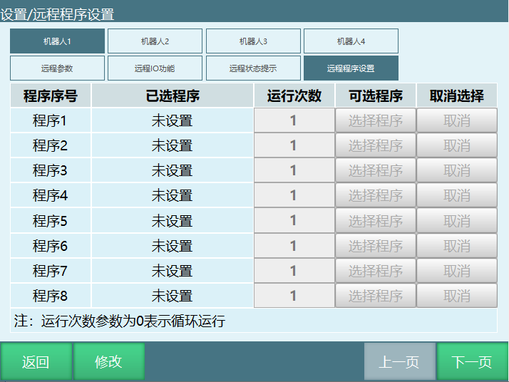
In the remote program settings interface, you can set the programs used by the touchscreen and I/O control module.
If there are multiple robots, you can select the robot to configure and set each program for that robot.
Programs used by the I/O control module must be set in the I/O function interface.
Programs already selected in the remote program interface can be cancelled by clicking the cancel button.
Enter the corresponding number for run count; 0 means loop execution.
4.3.3 Reservation Mode
In [Settings > Operation Parameters]:
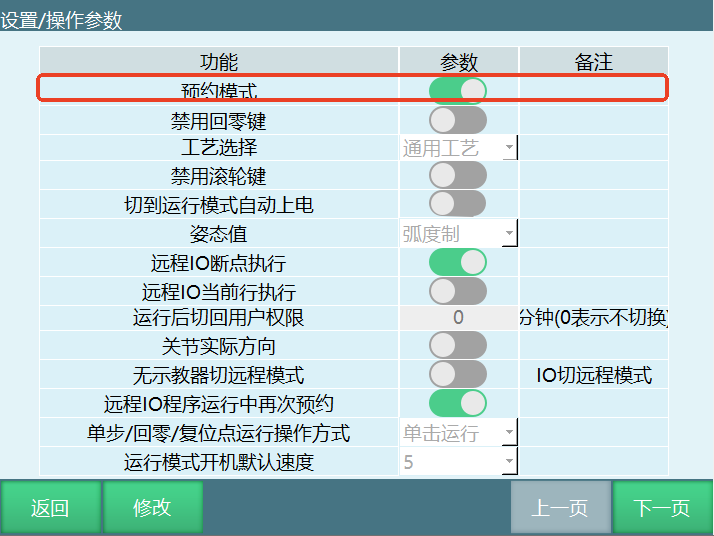
After enabling reservation mode: Trigger the remote IO program signal, the program is successfully reserved, trigger the start signal, and the robot runs.
After disabling reservation mode: Trigger the remote IO program signal, the robot runs directly. Triggering other remote IO program signals at this time is invalid. After the robot finishes running, remote IO program signals can be triggered again. No start signal needs to be set.
5 Using Remote Functions
5.1 Remote Function Overview
Set 10 remote programs and the run count for each program. Before running, queue the 10 programs. During execution, they run in queue order with the specified run counts. After the queue completes, the system stops and waits for re-queuing.
Remote function usage steps:
Write Program → Set Remote Program → Set IO → Switch to Remote Mode → Reserve and Queue → Run.
- Write Program:
Create a new program and insert instructions. Ensure the program can run normally.
- Set Remote Program:
Enter the "Settings > Remote Program Settings" interface, set the program names and run counts for Program 1 through Program 10. To run a single program in an infinite loop, set that program's run count to 0. The program names here reference programs in the "Project" interface. When instructions within a program are modified, the remote program automatically updates; no need to reconfigure.
If a program's name is modified, reconfigure that program in the remote program settings interface.
- Set IO:
In the "IO > IO Function" interface, set the IO ports and active values for each function. When the active value is 1, high level is active; when 0, low level is active.
The IO port functions for Program 1 through Program 10 do not select that program to run, but rather queue that program in remote mode.
- Switch to Remote Mode:
Turn the mode selection key to the remote mode position or click the mode status in the program and select remote mode.
When the teach pendant is not connected to the controller, starting the controller automatically enters remote mode.
When the controller is simultaneously connected to IO, Modbus device, and teach pendant, the priority of the three devices is: Teach Pendant > Modbus Device > IO Device. After switching to remote mode, the Modbus device is active and the IO device is inactive. At this point, disabling the enable button in the Modbus device makes the IO active.
- Reserve and Queue:
Example: IO function settings:
Start: Port 1, active value 1
Stop: Port 2, active value 1
Pause: Port 3, active value 1
Clear Error: Port 4, active value 1
Program 1: Port 5, active value 1
Program 2: Port 6, active value 1
Program 3: Port 7, active value 1
Program 4: Port 8, active value 1
Program 5: Port 9, active value 1
Program 6: Port 10, active value 1
Program 7: Port 11, active value 1
Program 8: Port 12, active value 1
Program 9: Port 13, active value 1
Program 10: Port 14, active value 1
The queuing method: give port 6 a high level for 1 second then release; Program 2 is queued first. Give port 8 a high level for 1 second then release; Program 4 is queued second. And so on. To cancel a program from the queue, give the corresponding IO port a 1-second high level again, and that program is removed from the queue.
The queue can hold a maximum of 10 programs; the same program cannot be queued multiple times.
When a program is running, it can be re-added to the end of the queue.
- Run:
Give the port with the run function a high level, and the robot starts running according to the queue order and run counts. After completion, the servo does not power off. At this point, adding a program to the queue causes the robot to run it immediately.
When the queue has no programs and the robot is started, the robot powers on but does not move. Adding a program to the queue at this point causes the robot to execute it immediately.
Viewing Run Status:
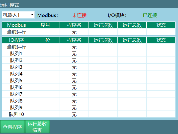
To view detailed program run status in remote IO control, click the "View Program" button in the remote mode interface. Modbus can also use this function to view.
Reset Run Total:
Clears the total run count of the currently running program. Only the run total can be cleared; the run count cannot.
Q&A for Retrieval
Q: What input/output instructions does the IO function support? A: The IO function supports: DIN (digital input), DOUT (digital output), AIN (analog input), AOUT (analog output), PULSEOUT (pulse output), READ_DOUT (read output).
Q: What is the DIN instruction used for? A: The DIN instruction reads digital input status into a variable, supporting 1-channel, 4-channel, and 8-channel input. It converts port status from binary to decimal and stores it in a variable.
Q: What output methods does the DOUT instruction support? A: The DOUT instruction supports manual selection and variable output. Manual selection directly checks port states; variable output converts the variable value from decimal to binary.
Q: What functions are included in IO status notification settings? A: IO status notification settings include: power-on notification, robot running status (running, paused, stopped), error notification, enable, mode status (teach/run/remote), emergency stop, main program first line, can continue execution, remove teach pendant, etc.
Q: What does IO safety settings include? A: IO safety settings include: emergency stop, safety light curtain, mask emergency stop, IO reset, IO configuration, enable IO, alarm messages, port names, etc.
Q: What types of IO reset functions are there? A: IO reset has three types: Remote IO Reset (triggered by reset signal in remote mode), Mode Switch Stop (mode switch causes program stop), Program Error Stop (program error causes stop).
Q: What signals does remote mode IO reservation support? A: Remote mode IO reservation supports: start, stop, pause, clear alarm, reservation = start, IO remote program 1-10, emergency stop, safety light curtain, mask emergency stop, and other digital IO input signals.
Q: What is the control authority priority in remote mode? A: Control authority priority: Teach Pendant > Touchscreen > IO Control Device.
Q: What connection methods does Modbus support? A: Modbus supports TCP and RTU connections, can act as master or slave, and supports multiple simultaneous client connections.
Q: What are the steps for remote program settings? A: Remote program setup steps: Write Program → Set Remote Program (Program 1-10 and run counts) → Set IO (IO ports for each function) → Switch to Remote Mode → Reserve and Queue → Run.
Version History
| Version | Date | Author | Changes |
|---|---|---|---|
| 1.0.0 | 2026-07-01 | tongmengyuan123 | Initial version |