INEXBOT Robot Auto Calibration System NexAutoCali Tutorial
Currently, the laser calibrator supports models including seven-axis serial multi-joint, seven-axis serial CBCBCBA, six-axis serial, six-axis collaborative, five-axis collaborative, four-axis SCARA, four-axis SCARA variant 1, etc. More models will be adapted in the future.
Performance testing currently supports trajectory accuracy (APt), trajectory repeatability (RPt), distance accuracy (ADp), distance repeatability (RDp), pose accuracy (APp), and pose repeatability (RPp). Other national standard 14 items will be gradually completed.
Calibration Function
The calibration function of the laser calibrator mainly calibrates the robot body parameters, mainly including DH parameters, reduction ratio, coupling ratio, etc.
Calibration Steps:
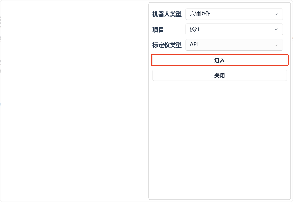
- Open the software on the computer, select the matching robot type, project (calibration or performance test), calibrator type (currently supports API and Zhongtu), then click [Enter].
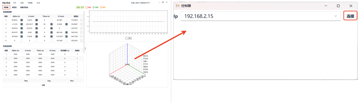
- Click [Controller], enter the IP address of the connected controller (using 192.168.3.15 as an example below), click [Connect].
(When connected successfully, the [Controller] button background color is green; when connection fails, the background color is white.)
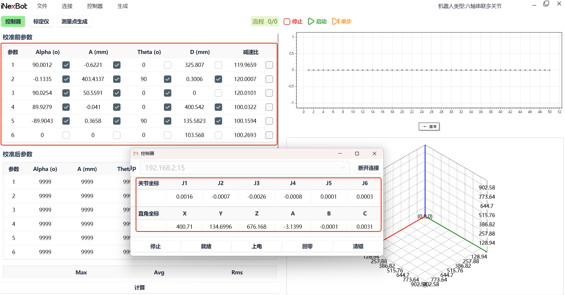
After connecting to the controller, it will automatically read the robot DH parameters and the current joint coordinates and Cartesian coordinate point information, as shown below:
- Connect the laser calibrator (using API as an example), click [Calibrator], click [Connect] in the popup.
(When connected successfully, the [Calibrator] button background color is green; when connection fails, the background color is white.)
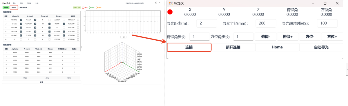
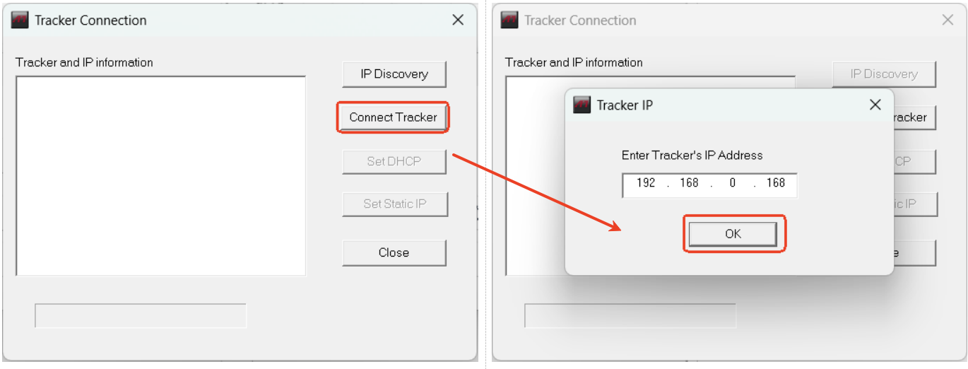
After clicking [Connect], click [Connect Tracker] and [OK] as shown in the figure below (no need to change the IP, the default IP for the API laser calibrator is 192.168.0.168).
After successfully connecting the calibrator, the calibrator popup will display the current laser calibrator target ball position information, as shown below:
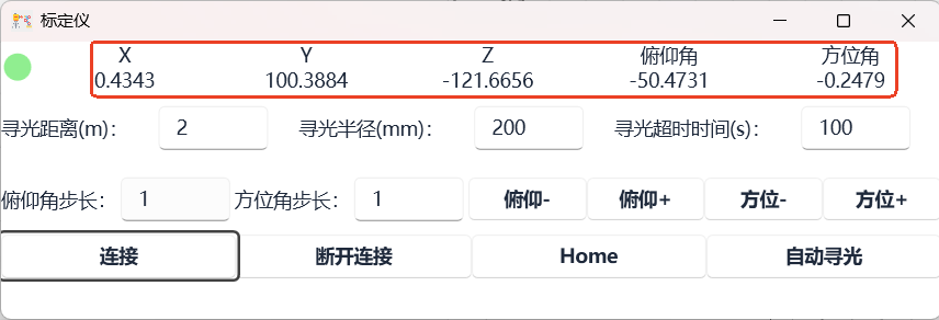
(After connecting the controller and calibrator successfully, place the target ball on the laser calibrator at the robot gripper, or use the "light guide" method to guide the laser to the target ball on the robot gripper.)
- Generate test points (usually 50 points)
Term explanations:
- Point count: Number of generated test points
- Pause time: Pause time between two adjacent points, generally "1-3"s
- Pose change: Default selection A, with four options: "None, A, B, C"
- Axis limit: Default no selection, not using limits. If the space is small or the robot is not connected, you can choose "Enable Cartesian limits or Enable joint limits or Enable both Cartesian and joint limits"
(Using Cartesian limits as an example, in Cartesian coordinates, move X-, X+, Y-, Y+, Z-, Z+, select appropriate positions and enter the teach pendant values in X, Y, Z negative limits and positive limits.)
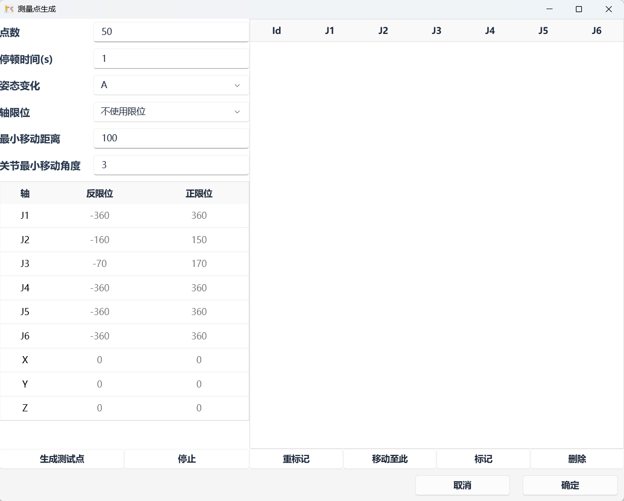

(After test point generation is complete, a prompt appears in the lower right corner.)
After measurement point generation is complete, click [Confirm] in the lower right corner.
- After point generation is complete, click [Start]. (Before clicking, ensure the robot is in powered-on state and the laser calibrator's laser is on the robot's target ball.)
Stop: Stop the calibration process.
Single Step:

After the test points are run, based on the checked items, a table will generate new calibrated parameters.
(The figure below shows the calibrated parameter screenshot using a six-axis collaborative robot as an example.)
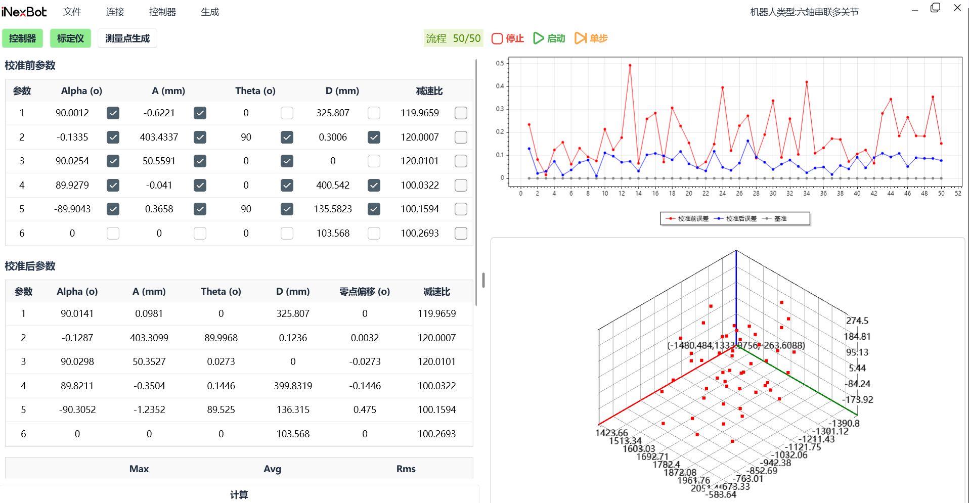
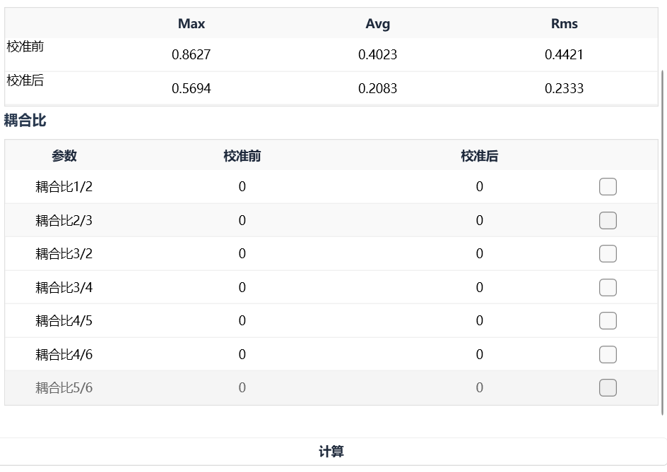
If you need to calculate different information, check the items yourself and click [Calculate].
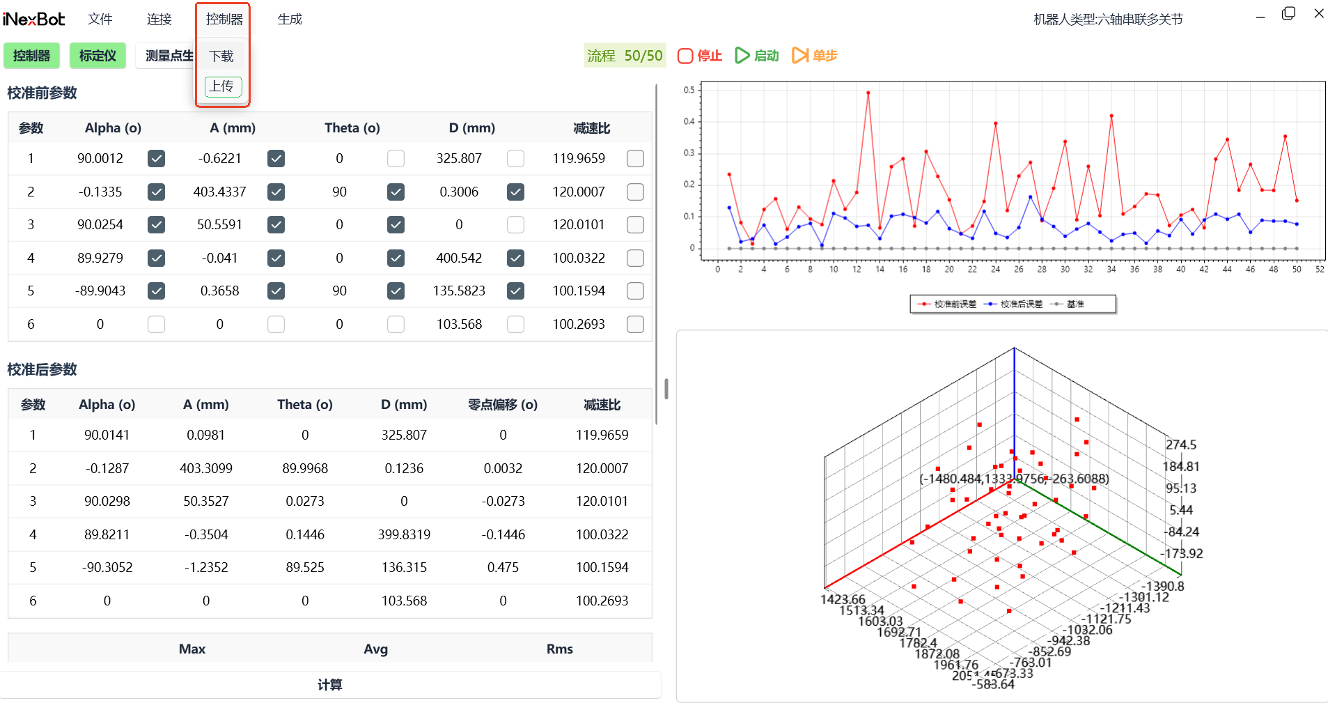
- Upload results to the controller. After calculation is complete, click [Controller] and then [Upload]. Download: Synchronize controller parameters to the software.
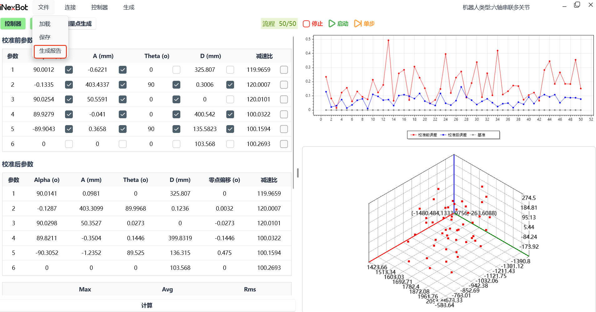
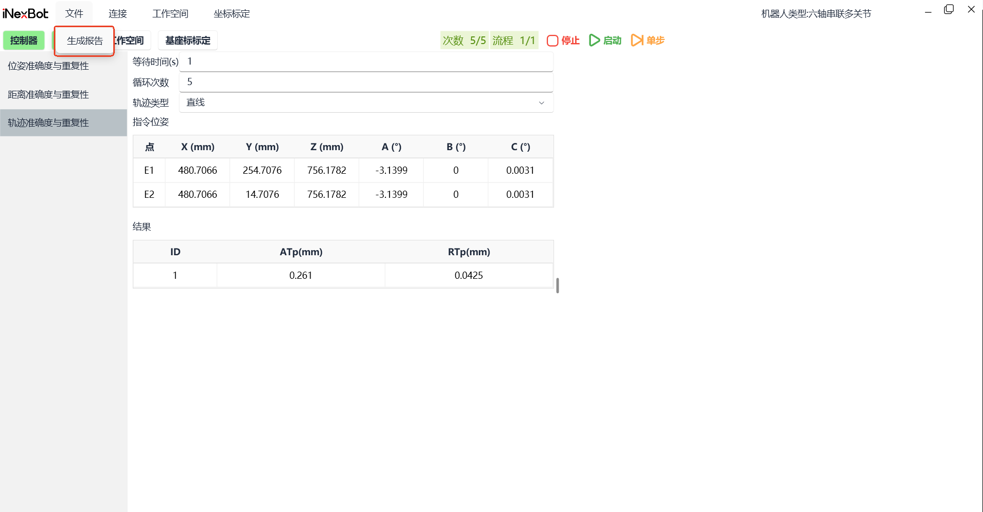
- Generate test report, click [File], click [Generate Report] in the dropdown.
Save: Save the complete record of this calibration process, generating a ".necal" file. Load: Open the saved necal file in the software again.
National Standard 14-Item Test Function
Before performing the 14-item test, ensure both the controller and calibrator are connected. The specific tutorial is above.
- Generate workspace, confirm pose test plane and trajectory test plane. Click [Workspace], as shown below:

"Pose Test Plane" parameter settings: Set the values of C7C6, C7C8, C7C3. The three values are based on the robot size and workspace settings. C7C8 is the Y-direction motion trajectory length of the robot. After setting the three parameters, click [Mark P1] and [Generate Test Points] at the robot zero point.
"Trajectory Test Plane" parameter settings: Same as pose test plane, C7C6, C7C8, C7C3 values should match those of the pose test plane.
After setting up "Pose Test Plane" and "Trajectory Test Plane", click [Confirm].
- Confirm the base coordinate, click [Base Coordinate Calibration], as shown below:
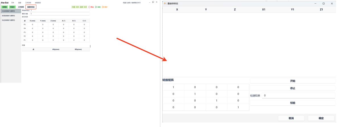
When the robot is at the "zero point", click [Start] (robot should be in powered-on state). The robot and laser calibrator will automatically perform calibration. After calibration is complete, a green popup will appear in the lower right corner, as shown below:

After calibration is complete, you can click [Verify]. Usually, the "Verification Result" value is within 1, indicating normal calibration. After calibration is complete, click [Confirm].
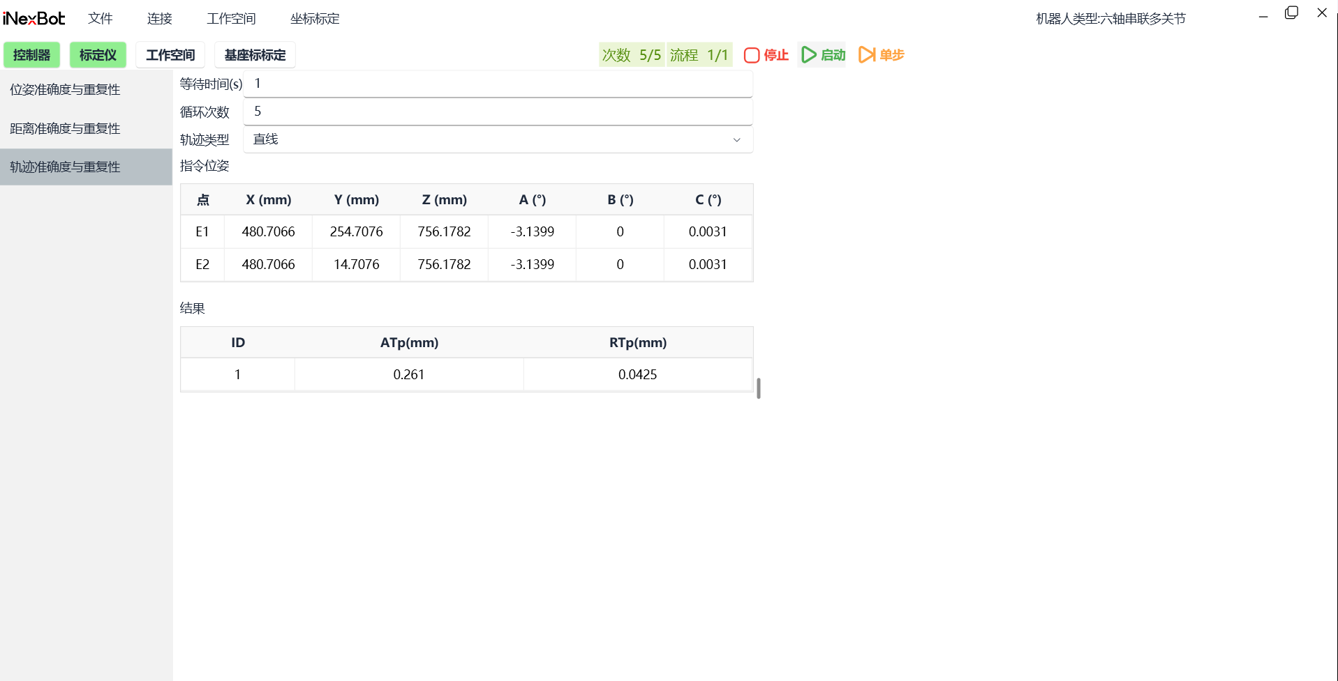
- Start the 14-item test, the figure below uses "Trajectory Accuracy and Repeatability" as an example.
Click [Trajectory Accuracy and Repeatability], fill in the wait time (default 3s) and cycle count. Trajectory types include "Line, Small Circle, Large Circle". After confirmation, click [Start]. Results will automatically appear at the bottom after execution, as shown below.
If you need to generate a corresponding report, click File, then click [Generate Report] in the dropdown.
Calibration Precautions:
Throughout the entire calibration and testing process, "light loss" must not occur.
If human-caused events lead to controller disconnection during calibration and testing, restart the controller to reconnect.
The calibrator must be placed on flat, hard ground (soft surfaces like flooring will affect measurement accuracy).
Minimize pedestrian movement around the calibrator during testing.
Before guiding light to the robot, ensure the calibrator data is stable (wait a few seconds after returning to Home point for data to stabilize).
Keep the test environment as stable as possible (e.g., not in a wind draft, not directly blown, etc.).
AI Retrieval Q&A (Q&A for Retrieval)
Q: What models does the laser calibrator currently support?
A: Currently supports seven-axis serial multi-joint, seven-axis serial CBCBCBA, six-axis serial, six-axis collaborative, five-axis collaborative, four-axis SCARA, four-axis SCARA variant 1, etc. More models will be adapted in the future.
Q: What performance test items are currently supported?
A: Currently supports trajectory accuracy (APt), trajectory repeatability (RPt), distance accuracy (ADp), distance repeatability (RDp), pose accuracy (APp), and pose repeatability (RPp). Other national standard 14 items will be gradually completed.
Q: What is the main calibration function of the laser calibrator?
A: The laser calibrator's calibration function mainly calibrates the robot body parameters, including DH parameters, reduction ratio, coupling ratio, etc.
Q: What are the calibration steps?
A: 1. Open the software on the computer, select the matching robot type, project, calibrator type, click [Enter]; 2. Click [Controller], enter the controller IP address, click [Connect]; 3. Connect the laser calibrator, click [Calibrator], click [Connect] in the popup, then click [Connect Tracker] and [OK]; 4. Generate test points (usually 50 points), set point count, pause time, pose change, axis limits, etc.; 5. After point generation, click [Start], ensure the robot is in powered-on state and the laser calibrator's laser is on the robot's target ball; 6. Upload results to the controller, after calculation click [Controller] and [Upload]; 7. Generate test report, click [File], click [Generate Report] in the dropdown.
Q: How to determine if the controller connection is successful?
A: When connected successfully, the [Controller] button background color is green; when connection fails, the background color is white.
Q: How to determine if the calibrator connection is successful?
A: When connected successfully, the [Calibrator] button background color is green; when connection fails, the background color is white. After successful connection, the calibrator popup will display the current laser calibrator target ball position information.
Q: What are point count, pause time, pose change, and axis limits?
A: Point count: Number of generated test points; Pause time: Pause time between two adjacent points, generally "1-3"s; Pose change: Default selection A, with four options: "None, A, B, C"; Axis limit: Default no selection, not using limits. If the space is small, you can choose "Enable Cartesian limits or Enable joint limits or Enable both Cartesian and joint limits".
Q: How to use the national standard 14-item test function?
A: 1. Generate workspace, confirm pose test plane and trajectory test plane, click [Workspace]; 2. Confirm the base coordinate, click [Base Coordinate Calibration], when the robot is at the "zero point", click [Start]; 3. Start the 14-item test, select the corresponding test item (e.g., trajectory accuracy and repeatability), fill in wait time and cycle count, select trajectory type, click [Start].
Q: How to verify if base coordinate calibration is normal?
A: After calibration is complete, click [Verify]. Usually, the "Verification Result" value is within 1, indicating normal calibration.
Q: What precautions should be taken during calibration?
A: 1. Throughout the entire calibration and testing process, "light loss" must not occur; 2. If human-caused events lead to controller disconnection, restart the controller to reconnect; 3. The calibrator must be placed on flat, hard ground; 4. Minimize pedestrian movement around the calibrator during testing; 5. Before guiding light to the robot, ensure the calibrator data is stable; 6. Keep the test environment as stable as possible.