Calculate Target Configuration Instruction
SOLVE_CONFIGURATION - Calculate Target Configuration Value
Function
When moving from point A (robot's current actual position) to another point B, the algorithm can calculate how many configurations the robot can use to move from A to B.
Usage Example
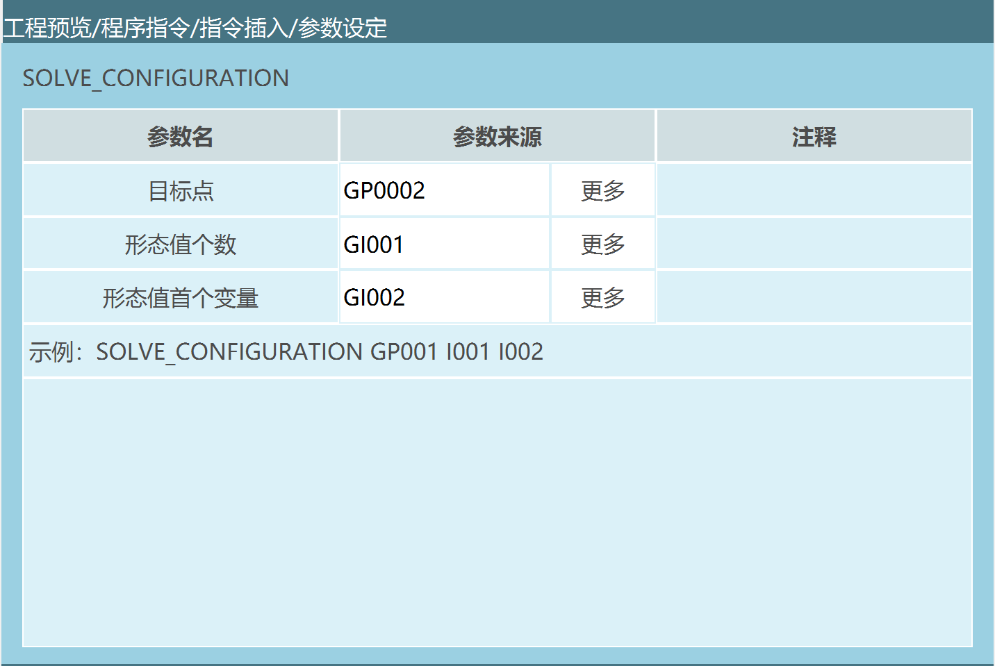
Parameter Description:
Target Point: The position the robot needs to move to.
Number of Configuration Values: The algorithm calculates how many configurations can reach from A to B (calculates the total number of configurations).
First Variable for Configuration Values: The first variable storing the calculated configuration value D (for example, if the algorithm calculates 3 configurations from A to B, as shown in the instruction description, the first configuration is 2, so GI002 stores 2, GI003 stores 3, GI004 stores 4).
Calculate Target Configuration Value G0001 GI001 GI002
Program Description
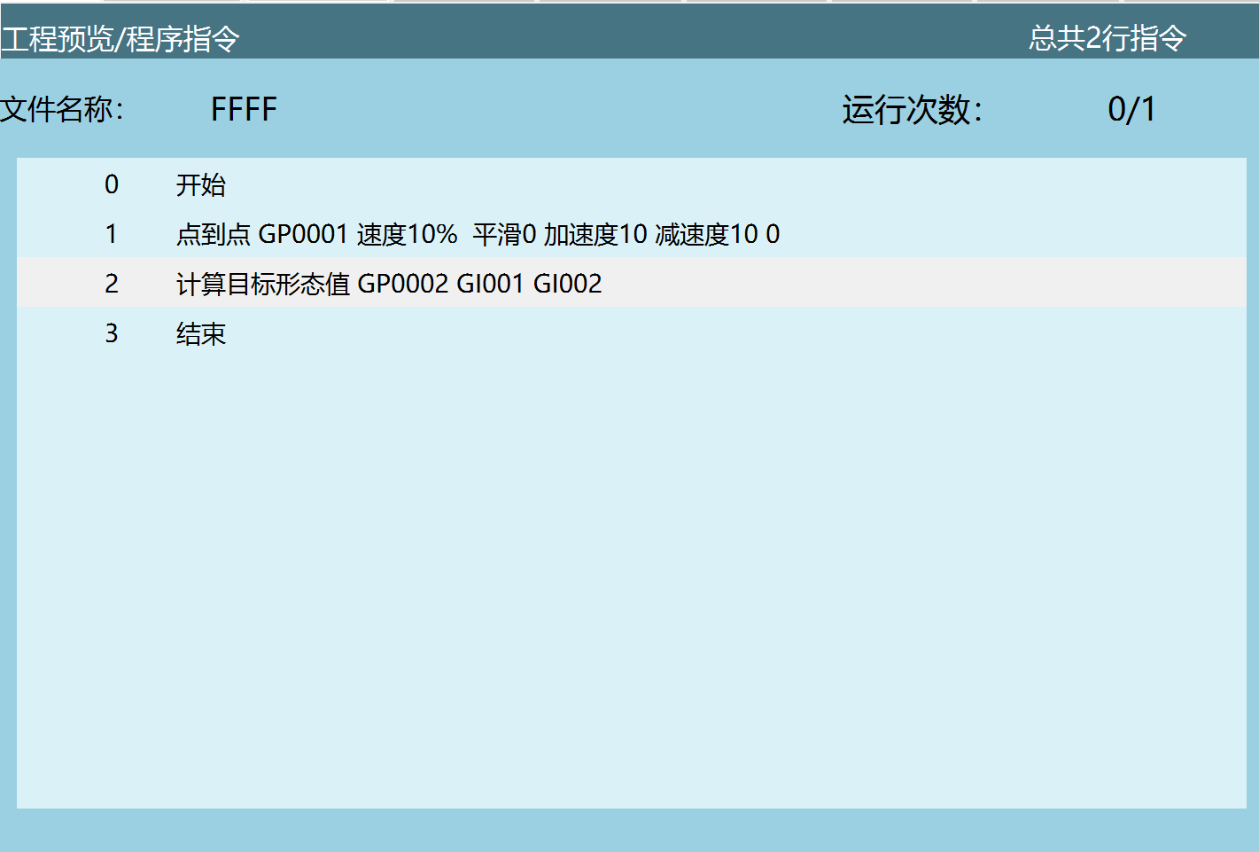
As shown above, there are now two instructions that need to use the calculate configuration value instruction from GP0001 to GP0002.
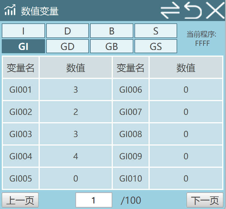
Through calculation, 3 configurations are found to reach GP002, and the number of configurations is stored in GI001.
3 configurations are calculated, and the first variable for the calculated configuration values is stored in GI002, where GI002=2. GI003=3, GI004=4.
**Precautions
The calculated configurations cannot be directly used by modifying the configuration value in the position parameter interface. You need to use the Set Position Information instruction to call the calculated configuration values.
Calculate Target Configuration Value Parameter Description:
*Configuration Value Calculation in Motion Instructions:
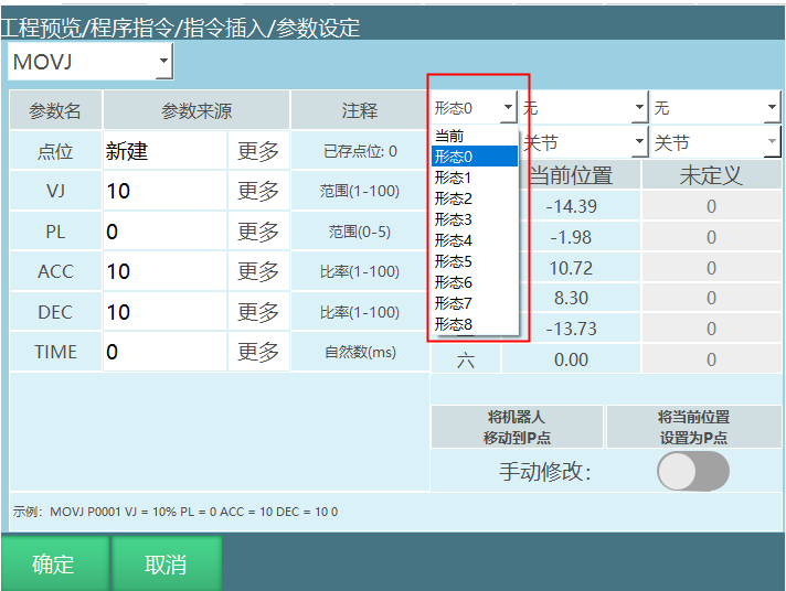
Configuration Parameter:
(If "Current" is selected, the control system automatically calculates which configuration value should be selected through conversion)
The configuration value is the binary conversion of the robot's axis 1, axis 3, and axis 5 positions.
Conversion Method:
For example, a six-axis robot has axis 1 at 59°, axis 2 at 69°, axis 3 at 79°, axis 4 at 89°, axis 5 at 99°, axis 6 at 109°.
Take axes 1/3/5: if the position range is between -90~+90, the value is 1; otherwise, it is 0.
So the result is as follows:
Axis Axis 1 Axis 3 Axis 5
Binary Value 1 1 0
Binary 110 = Decimal 6.
Configuration value = Decimal result + 1, so the configuration value for this point is 7.
Precautions
If you need to use the calculated configuration, you need to use the Set Position instruction to call the calculated configuration for use.
Six-Axis Serial Configuration Value Calculation Optimization
The calculation rules for configuration values have been optimized once, with optimizations made to the binary conversion of J1; there are no major overall changes.
The configuration value is the binary conversion value of the shoulder configuration (originally axis 1), elbow configuration (originally axis 3), and wrist configuration (originally axis 5).
The conversion method is as follows:
(1) Shoulder Configuration Value
Judgment Rule: Whether the axis intersection point of axes 4, 5, and 6 is in front of the J1 axis line. If in front, the shoulder configuration value is 1; if not in front, the shoulder configuration value is 0.
As shown in the diagram, the shoulder configuration value is 1.
Note: The shoulder configuration value is no longer related to the degree of J1. It is affected by the combined influence of J2, J3, and J4. Only look at whether the intersection point is in front or behind. The diagram shows the shoulder configuration value as 1; even if J1 rotates 180 degrees, it is still in front.
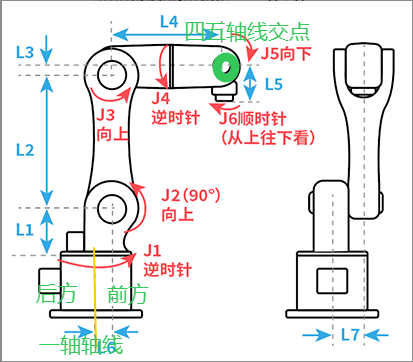
(2) Elbow Configuration Value
Judgment Rule: -90 < Axis J3 degree < 90, the elbow configuration value is 1; otherwise, it is 0.
In the diagram, J3 is at zero point, so the elbow configuration value is 1.
(3) Wrist Configuration Value
Judgment Rule: Using the point where the axis 5 part and the forearm are collinear as the dividing point. When folded downward, the wrist configuration value is 1; otherwise, it is 0.
Typically using the position shown as the zero point, the judgment rule is: -90 < Axis J5 degree < 90, the wrist configuration value is 1; otherwise, it is 0. The wrist configuration value in the diagram is 1.
Another case is when the axis 5 horizontal zero point position is used, the judgment rule is: 0 < Axis J5 degree < 180, the wrist configuration value is 1; otherwise, it is 0.
- Configuration Value Calculation
The three configuration values together form a binary number, 111.
Configuration Value = 4 * Shoulder Configuration + 2 * Elbow Configuration + Wrist Configuration + 1.
The configuration value at the diagram position is: 41 + 21 + 1 + 1 = 8.
AI Retrieval Q&A (Q&A for Retrieval)
Q: What is the purpose of the SOLVE_CONFIGURATION instruction?
A: It is used to calculate all feasible "configurations (poses)" when the robot moves from current point A to target point B. The output includes the total number of reachable configurations and the configuration value corresponding to each configuration.
Q: How are the calculated configuration values stored?
A: They are stored through consecutive register variables. For example: GI001 stores the number of configurations, GI002 stores the first configuration value, GI003, GI004... store subsequent configuration values sequentially. Essentially, values are written sequentially into a group of consecutive variables.
Q: Can the calculated configuration values be used directly?
A: They cannot be used directly by modifying values in the position parameter interface. The correct method is to use the "Set Position Information" instruction to write the calculated configuration value into the position before use.
Q: How are configuration values calculated?
A: Based on the robot's key axes (typically axes 1, 3, 5 or shoulder/elbow/wrist), binary values are generated. Values within the specified angle range are marked as 1, and those outside the range are marked as 0. Then the binary is converted to decimal, and 1 is added to get the final configuration value.
Q: What is the optimization content for six-axis serial configuration value calculation?
A: 1. The calculation rules for configuration values have been optimized, with optimizations to the binary conversion of J1; there are no major overall changes. 2. The configuration value is the binary conversion value of the shoulder configuration (originally axis 1), elbow configuration (originally axis 3), and wrist configuration (originally axis 5). 3. Shoulder configuration judgment rule: Whether the axis intersection of axes 4, 5, and 6 is in front of the J1 axis line; 1 if in front, 0 if not. 4. Elbow configuration judgment rule: -90 < Axis J3 degree < 90, 1 if true, 0 if not. 5. Wrist configuration judgment rule: Using the point where axis 5 part and forearm are collinear as the dividing point; 1 when folded downward, 0 otherwise. 6. Configuration value calculation: 4 * Shoulder Configuration + 2 * Elbow Configuration + Wrist Configuration + 1.