Robot DH Parameters
Precautions
- All parameter values need to be measured at the robot zero position
- Incorrect parameter configuration may cause abnormal robot motion or errors
- After modifying parameters, the controller needs to be restarted to take effect
- Parameter configuration is recommended under professional guidance
- DH parameters are the foundation of robot precision. Inaccurate parameters directly affect end positioning precision
DH Parameters (Standard Method)
DH parameters are the standard method for robot kinematic modeling, proposed by Denavit and Hartenberg in 1955. They describe the geometric relationship between adjacent links through four parameters. Accurate DH parameters are the foundation of robot precision calibration, directly affecting the precision of forward and inverse kinematics calculations.
DH Parameter Coordinate System Establishment Rules
For each link i, establish coordinate system {i} following these rules:
- Z-axis: Along the motion axis of joint i (rotation axis for rotary joints, translation axis for prismatic joints)
- X-axis: Perpendicular to Z-axis, pointing toward joint i+1, the common perpendicular direction of Z_{i-1} and Z_i
- Y-axis: Determined by the right-hand rule, Y_i = Z_i × X_i
- Origin: At the intersection of X_i and Z_i
DH Parameter Description
| Parameter | Symbol | Description | Physical Meaning | Precision Impact |
|---|---|---|---|---|
| Link Length | a_i | Common perpendicular length from joint i-1 axis (Z_{i-1}) to joint i axis (Z_i) | Distance between two joint axes in the plane perpendicular to the common perpendicular | Directly affects end position precision |
| Link Twist | α_i | Angle between joint i-1 axis (Z_{i-1}) and joint i axis (Z_i) | Spatial angle between two joint axes, measured around the common perpendicular (X_i) | Affects end orientation precision |
| Link Offset | d_i | Distance along joint i-1 axis (Z_{i-1}) direction from joint i-1 coordinate system origin (O_{i-1}) to the common perpendicular | Displacement along the previous joint axis | Affects axial positioning precision |
| Joint Angle | θ_i | Rotation angle around joint i axis (Z_i) | Joint rotation angle (rotary joint) or displacement (prismatic joint) | Affects each joint's positioning precision |
DH Parameter Function Details
1. Link Length (a_i)
- Function: Defines the perpendicular distance between two adjacent joint axes
- Measurement: At the robot zero position, measure the common perpendicular segment length from joint i-1 axis to joint i axis
- Impact: Directly affects the robot's workspace range and kinematic calculation precision
2. Link Twist (α_i)
- Function: Defines the spatial angle between two adjacent joint axes
- Measurement: Measure the angle between joint i-1 axis and joint i axis around the common perpendicular
- Impact: Determines the twist relationship between links, affects the robot's orientation reachability and orientation precision
3. Link Offset (d_i)
- Function: Defines the displacement along the joint axis direction
- Measurement: Along joint i-1 axis, from joint i-1 coordinate system origin to the common perpendicular distance
- Impact: For rotary joints, this parameter is constant; for prismatic joints, this parameter is the joint variable
4. Joint Angle (θ_i)
- Function: Defines the joint rotation angle
- Measurement: Rotation angle around joint i axis
- Impact: For rotary joints, this parameter is the joint variable; for prismatic joints, this parameter is constant
7-Axis Serial Robot - CBCBABC
Reference Zero Point
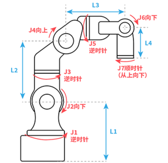
Link Length Parameters
| Parameter | Description | Parameter Value Sign Convention (reference Cartesian coordinate system direction at robot zero position) |
|---|---|---|
| L1 | Length from robot base surface to axis 2 rotation axis common perpendicular segment | Positive in Z+ direction |
| L2 | Length from axis 2 rotation axis to axis 3 rotation axis common perpendicular segment | Positive in Z+ direction |
| L3 | Length in Z-axis direction from axis 3 rotation axis to axis 5 rotation axis | Positive in Z+ direction |
| L4 | Length in X-axis direction from axis 3 rotation axis to axis 5 rotation axis | Positive in X+ direction |
| L5 | Length from axis 5 rotation axis to axis 6 flange surface common perpendicular segment | Positive in Z- direction |
| L6 | Length from axis 1 rotation axis to axis 2 rotation axis common perpendicular segment | Positive in X+ direction |
| L7 | Length in Y-axis direction from axis 1 rotation axis to axis 4 rotation axis | Positive in Y+ direction |
| L8 | Length from axis 4 rotation axis to axis 6 rotation axis common perpendicular segment | Positive in Y+ direction |
| L9 | Length from axis 6 rotation axis to axis 7 rotation axis common perpendicular segment | Positive in X+ direction |
| L10 | Length from axis 7 rotation axis to end flange surface common perpendicular segment | Positive in Z- direction |
Coupling Ratio
During robot motion, when one joint moves, another joint also moves, indicating coupling. To offset this coupling effect, coupling ratio parameters need to be set.
Coupling ratio formula: Coupling Ratio = Follower Axis Rotation Angle / Main Axis Rotation Angle
Five-Axis Direction
The direction of the five-axis when the robot is at the zero position. If the five-axis direction during zero point calibration is inconsistent with the five-axis direction selected in the DH parameter interface, the robot will report an error during motion.
Model Direction (Zero Point Rotation Direction)
| Parameter | Parameter Value Sign Convention (from top to bottom, from front to back, from left to right) |
|---|---|
| J1 | Counterclockwise |
| J2 | Counterclockwise |
| J3 | Counterclockwise |
| J4 | Counterclockwise |
| J5 | Clockwise |
| J6 | Clockwise |
| J7 | Counterclockwise |
6-Axis Serial Multi-Joint Robot - CBBABC
Reference Zero Point
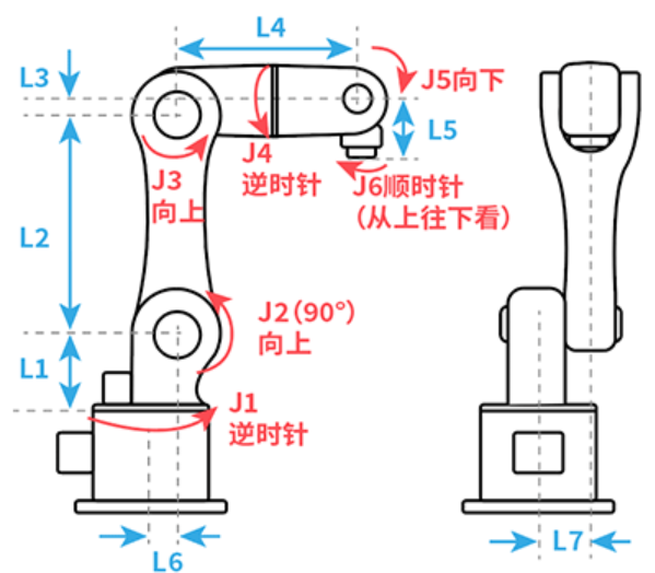
Link Length Parameters
| Parameter | Description | Parameter Value Sign Convention (reference Cartesian coordinate system direction at robot zero position) |
|---|---|---|
| L1 | Length from robot base surface to axis 2 rotation axis common perpendicular segment | Positive in Z+ direction |
| L2 | Length from axis 2 rotation axis to axis 3 rotation axis common perpendicular segment | Positive in Z+ direction |
| L3 | Length in Z-axis direction from axis 3 rotation axis to axis 5 rotation axis | Positive in Z+ direction |
| L4 | Length in X-axis direction from axis 3 rotation axis to axis 5 rotation axis | Positive in X+ direction |
| L5 | Length from axis 5 rotation axis to axis 6 flange surface common perpendicular segment | Positive in Z- direction |
| L6 | Length from axis 1 rotation axis to axis 2 rotation axis common perpendicular segment | Positive in X+ direction |
| L7 | Length in Y-axis direction from axis 1 rotation axis to axis 4 rotation axis | Positive in Y+ direction |
| L8 | Length from axis 4 rotation axis to axis 6 rotation axis common perpendicular segment | Positive in Y+ direction |
Five-Axis Direction
The direction of the five-axis when the robot is at the zero position. If the five-axis direction during zero point calibration is inconsistent with the five-axis direction selected in the DH parameter interface, the robot will report an error during motion.
Model Direction (Zero Point Rotation Direction)
| Parameter | Parameter Value Sign Convention (from top to bottom, from front to back, from left to right) |
|---|---|
| J1 | Counterclockwise |
| J2 | Counterclockwise |
| J3 | Counterclockwise |
| J4 | Counterclockwise |
| J5 | Clockwise |
| J6 | Clockwise |
6-Axis Collaborative Robot - CBBBAC
Reference Zero Point
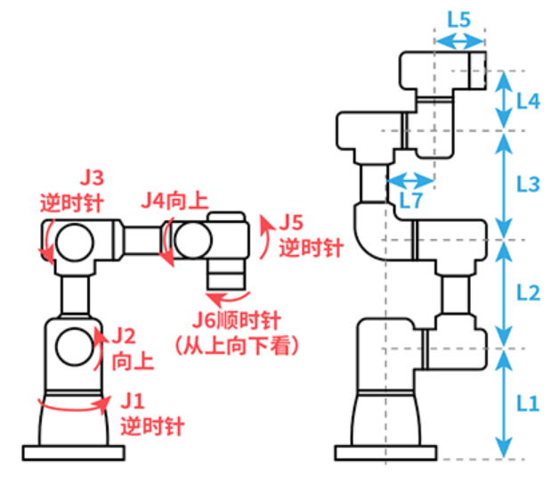
Link Length Parameters
| Parameter | Description | Parameter Value Sign Convention (reference Cartesian coordinate system direction at robot zero position) |
|---|---|---|
| L1 | Length from robot base surface to axis 2 rotation axis common perpendicular segment | Positive in Z+ direction |
| L2 | Length from axis 2 rotation axis to axis 3 rotation axis common perpendicular segment | Positive in Z+ direction |
| L3 | Length from axis 3 rotation axis to axis 4 rotation axis common perpendicular segment | Positive in X+ direction |
| L4 | Length from axis 4 rotation axis to axis 6 rotation axis common perpendicular segment | Positive in X+ direction |
| L5 | Length from axis 5 rotation axis to axis 6 flange surface common perpendicular segment | Positive in Z- direction |
| L6 | Length from axis 1 rotation axis to axis 2 rotation axis common perpendicular segment | Positive in X+ direction |
| L7 | Length from axis 1 rotation axis to axis 5 rotation axis common perpendicular segment | Positive in Y- direction |
Coupling Ratio
During robot motion, when one joint moves, another joint also moves, indicating coupling. To offset this coupling effect, coupling ratio parameters need to be set.
Coupling ratio formula: Coupling Ratio = Follower Axis Rotation Angle / Main Axis Rotation Angle
Three-Axis Direction, Five-Axis Direction
The direction of the three-axis and five-axis when the robot is at the zero position. If the direction during zero point calibration is inconsistent with the direction selected in the DH parameter interface, the robot will report an error during motion.
Model Direction (Zero Point Rotation Direction)
| Parameter | Parameter Value Sign Convention (from top to bottom, from front to back, from left to right) |
|---|---|
| J1 | Counterclockwise |
| J2 | Counterclockwise |
| J3 | Counterclockwise |
| J4 | Counterclockwise |
| J5 | Counterclockwise |
| J6 | Clockwise |
6-Axis Spraying Robot - CBBBCA
Reference Zero Point
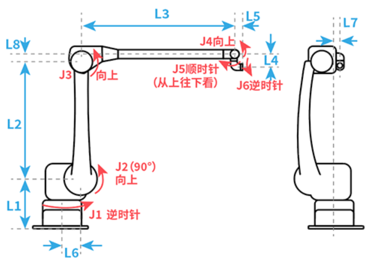
Link Length Parameters
| Parameter | Description | Parameter Value Sign Convention (reference Cartesian coordinate system direction at robot zero position) |
|---|---|---|
| L1 | Length from robot base surface to axis 2 rotation axis common perpendicular segment | Positive in Z+ direction |
| L2 | Length from axis 2 rotation axis to axis 3 rotation axis common perpendicular segment | Positive in Z+ direction |
| L3 | Length in X-axis direction from axis 3 rotation axis to axis 4 rotation axis | Positive in X+ direction |
| L4 | Length from axis 4 rotation axis to axis 6 rotation axis common perpendicular segment | Positive in Z- direction |
| L5 | Length from axis 4 rotation axis to axis 6 flange surface common perpendicular segment | Positive in X+ direction |
| L6 | Length from axis 1 rotation axis to axis 2 rotation axis common perpendicular segment | Positive in X+ direction |
| L7 | Length from axis 1 rotation axis to axis 6 rotation axis common perpendicular segment | Positive in Y+ direction |
| L8 | Length in Z-axis direction from axis 3 rotation axis to axis 4 rotation axis | Positive in Z+ direction |
Coupling Ratio
During robot motion, when one joint moves, another joint also moves, indicating coupling. To offset this coupling effect, coupling ratio parameters need to be set.
Coupling ratio formula: Coupling Ratio = Follower Axis Rotation Angle / Main Axis Rotation Angle
Model Direction (Zero Point Rotation Direction)
| Parameter | Parameter Value Sign Convention (from top to bottom, from front to back, from left to right) |
|---|---|
| J1 | Counterclockwise |
| J2 | Counterclockwise |
| J3 | Counterclockwise |
| J4 | Counterclockwise |
| J5 | Clockwise |
| J6 | Counterclockwise |
6-Axis Special-Shaped Type 2 Robot - CCBABC
Reference Zero Point
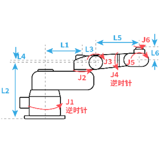
Link Length Parameters
| Parameter | Description | Parameter Value Sign Convention (reference Cartesian coordinate system direction at robot zero position) |
|---|---|---|
| L1 | Length from axis 1 rotation axis to axis 2 rotation axis common perpendicular segment | Positive in X+ direction |
| L2 | Length from robot base surface to axis 3 rotation axis common perpendicular segment | Positive in Z+ direction |
| L3 | Length from axis 2 rotation axis to axis 3 rotation axis common perpendicular segment | Positive in X+ direction |
| L4 | Length in Z-axis direction from axis 3 rotation axis to axis 5 rotation axis | Positive in Z+ direction |
| L5 | Length from axis 3 rotation axis to axis 6 rotation axis common perpendicular segment | Positive in X+ direction |
| L6 | Length from axis 5 rotation axis to axis 6 flange surface common perpendicular segment | Positive in Z+ direction |
Coupling Ratio
During robot motion, when one joint moves, another joint also moves, indicating coupling. To offset this coupling effect, coupling ratio parameters need to be set.
Coupling ratio formula: Coupling Ratio = Follower Axis Rotation Angle / Main Axis Rotation Angle
Model Direction (Zero Point Rotation Direction)
| Parameter | Parameter Value Sign Convention (from top to bottom, from front to back, from left to right) |
|---|---|
| J1 | Counterclockwise |
| J2 | Counterclockwise |
| J3 | Clockwise |
| J4 | Counterclockwise |
| J5 | Clockwise |
| J6 | Counterclockwise |
5-Axis Serial Multi-Joint Robot - CBBAB
Reference Zero Point
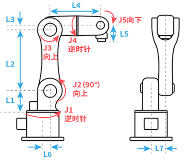
Link Length Parameters
| Parameter | Description | Parameter Value Sign Convention (reference Cartesian coordinate system direction at robot zero position) |
|---|---|---|
| L1 | Length from robot base surface to axis 2 rotation axis common perpendicular segment | Positive in Z+ direction |
| L2 | Length from axis 2 rotation axis to axis 3 rotation axis common perpendicular segment | Positive in Z+ direction |
| L3 | Length in Z-axis direction from axis 3 rotation axis to axis 5 rotation axis | Positive in Z+ direction |
| L4 | Length in X-axis direction from axis 3 rotation axis to axis 5 rotation axis | Positive in X+ direction |
| L5 | Length from axis 5 rotation axis to tool hand flange common perpendicular segment | Positive in Z- direction |
| L6 | Length from axis 1 rotation axis to axis 2 rotation axis common perpendicular segment | Positive in X+ direction |
| L7 | Length in Y-axis direction from axis 1 rotation axis to axis 6 rotation axis | Positive in Y+ direction |
Coupling Ratio
During robot motion, when one joint moves, another joint also moves, indicating coupling. To offset this coupling effect, coupling ratio parameters need to be set.
Coupling ratio formula: Coupling Ratio = Follower Axis Rotation Angle / Main Axis Rotation Angle
Five-Axis Direction
The direction of the five-axis when the robot is at the zero position. If the five-axis direction during zero point calibration is inconsistent with the five-axis direction selected in the DH parameter interface, the robot will report an error during motion.
Model Direction (Zero Point Rotation Direction)
| Parameter | Parameter Value Sign Convention (from top to bottom, from front to back, from left to right) |
|---|---|
| J1 | Counterclockwise |
| J2 | Counterclockwise |
| J3 | Counterclockwise |
| J4 | Counterclockwise |
| J5 | Clockwise |
4-Axis SCARA Robot - CCZC
Structural Features
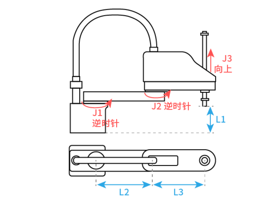
SCARA (Selective Compliance Assembly Robot Arm) robot has 4 axes, where the first two axes are rotary axes, the third axis is a prismatic axis, and the fourth axis is a rotary axis.
Link Length Parameters
| Parameter | Description | Parameter Value Sign Convention (reference Cartesian coordinate system direction at robot zero position) |
|---|---|---|
| L1 | Length from robot base surface to axis 3 flange surface common perpendicular segment | Positive in Z+ direction |
| L2 | Length from axis 1 rotation axis to axis 2 rotation axis common perpendicular segment | Positive in X+ direction |
| L3 | Length from axis 2 rotation axis to axis 4 rotation axis common perpendicular segment | Positive in X+ direction |
Coupling Ratio
During robot motion, when one joint moves, another joint also moves, indicating coupling. To offset this coupling effect, coupling ratio parameters need to be set.
Coupling ratio formula: Coupling Ratio = Follower Axis Rotation Angle / Main Axis Rotation Angle
Pitch
The SCARA robot's 3rd axis controls the screw's up-down movement. The distance the screw moves up-down when the controlling rotary axis rotates 360° is the pitch.
Model Direction (Zero Point Rotation Direction)
| Parameter | Parameter Value Sign Convention (from top to bottom, from front to back, from left to right) |
|---|---|
| J1 | Counterclockwise |
| J2 | Counterclockwise |
| J3 | Upward |
| J4 | Clockwise |
4-Axis SCARA Special-Shaped Type 1 Robot - ZCCC
Reference Zero Point
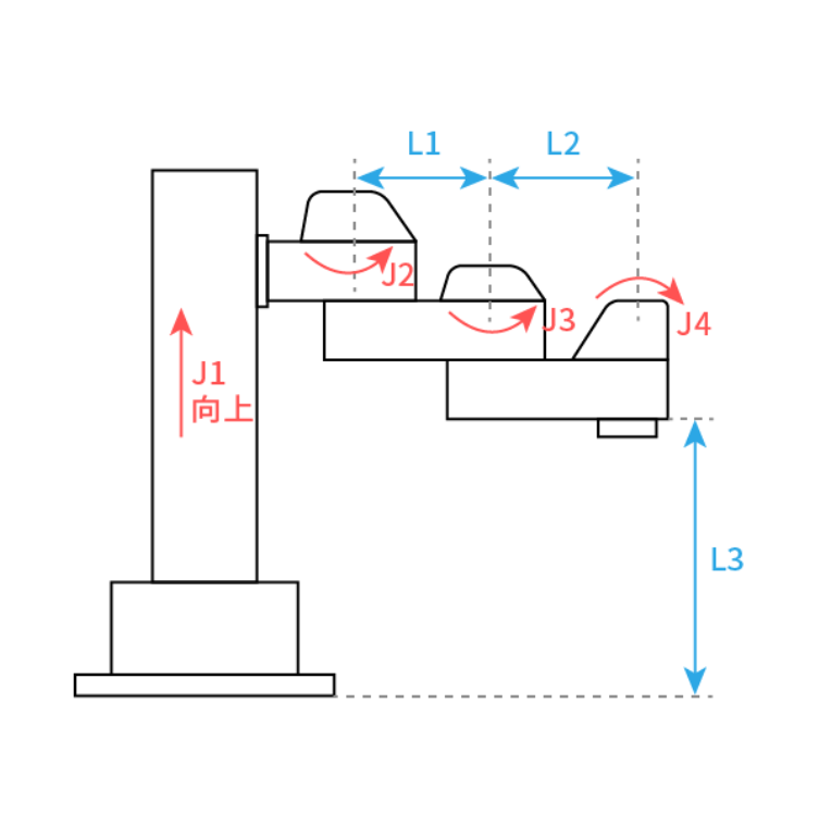
Link Length Parameters
| Parameter | Description | Parameter Value Sign Convention (reference Cartesian coordinate system direction at robot zero position) |
|---|---|---|
| L1 | Length from axis 2 rotation axis to axis 3 rotation axis common perpendicular segment | Positive in X+ direction |
| L2 | Length from axis 3 rotation axis to axis 4 rotation axis common perpendicular segment | Positive in X+ direction |
| L3 | Length from robot base to axis 4 flange surface common perpendicular segment | Positive in Z+ direction |
Coupling Ratio
During robot motion, when one joint moves, another joint also moves, indicating coupling. To offset this coupling effect, coupling ratio parameters need to be set.
Coupling ratio formula: Coupling Ratio = Follower Axis Rotation Angle / Main Axis Rotation Angle
Pitch
The SCARA robot's 3rd axis controls the screw's up-down movement. The distance the screw moves up-down when the controlling rotary axis rotates 360° is the pitch.
Model Direction (Zero Point Rotation Direction)
| Parameter | Parameter Value Sign Convention (from top to bottom, from front to back, from left to right) |
|---|---|
| J1 | Upward |
| J2 | Counterclockwise |
| J3 | Counterclockwise |
| J4 | Clockwise |
4-Axis Linkage Palletizing Robot - CBBC
Reference Zero Point
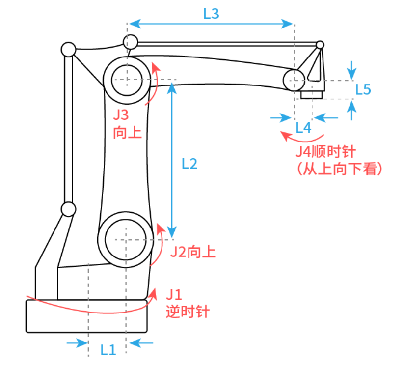
Link Length Parameters
| Parameter | Description | Parameter Value Sign Convention (reference Cartesian coordinate system direction at robot zero position) |
|---|---|---|
| L1 | Length in X-axis direction from axis 1 rotation axis to axis 2 rotation axis | Positive in X+ direction |
| L2 | Length from axis 2 rotation axis to axis 3 rotation axis common perpendicular segment | Positive in Z+ direction |
| L3 | Length from axis 3 rotation axis to linkage axis rotation axis common perpendicular segment | Positive in X+ direction |
| L4 | Length from linkage axis rotation axis to axis 4 rotation center common perpendicular segment | Positive in X+ direction |
| L5 | Length from linkage axis rotation axis to axis 4 flange surface common perpendicular segment | Positive in Z- direction |
| L6 | Distance in Y-axis direction from axis 1 rotation axis to axis 4 rotation axis | Positive in Y+ direction |
Coupling Ratio
During robot motion, when one joint moves, another joint also moves, indicating coupling. To offset this coupling effect, coupling ratio parameters need to be set.
Coupling ratio formula: Coupling Ratio = Follower Axis Rotation Angle / Main Axis Rotation Angle
J2+J3 Limit
Dynamic limits only take effect when axes 2/3 have coupling. When J2+J3 maximum and J2+J3 minimum are not within the set parameter range, an error will occur during program execution (Robot axes 2, 3 dynamic limit exceeded).
Model Direction (Zero Point Rotation Direction)
| Parameter | Parameter Value Sign Convention (from top to bottom, from front to back, from left to right) |
|---|---|
| J1 | Counterclockwise |
| J2 | Counterclockwise |
| J3 | Counterclockwise |
| J4 | Clockwise |
4-Axis Palletizing Screw Robot - CZXC
Reference Zero Point
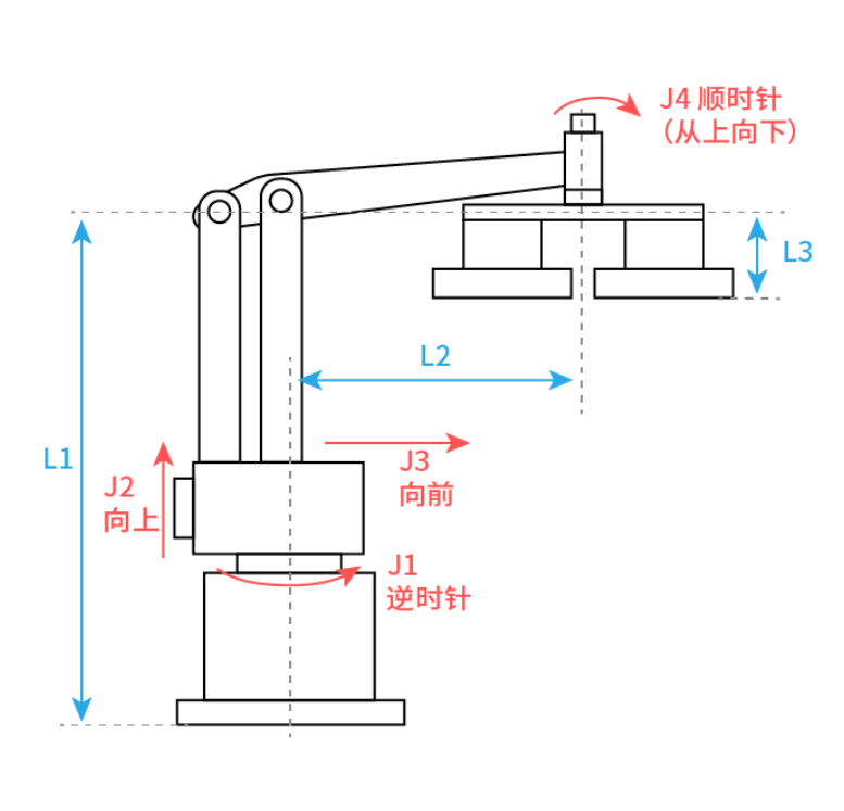
Link Length Parameters
| Parameter | Description | Parameter Value Sign Convention (reference Cartesian coordinate system direction at robot zero position) |
|---|---|---|
| L1 | Length from robot base to double-arm structure outer arm upper rotation axis common perpendicular segment | Positive in Z+ direction |
| L2 | Length from axis 1 rotation axis to axis 4 rotation axis common perpendicular segment | Positive in X+ direction |
| L3 | Distance from axis 4 flange surface to tool tip surface, default 0 | Positive in Z- direction |
Conversion Ratio
The conversion ratio is the distance (unit: mm) traveled when the joint rotates 360 degrees (also understood as one motor revolution). For example: when the motor rotates one revolution, there will be an angle value. Through the conversion ratio, we can convert the angle value to a length value.
Amplification Ratio
Distance the tool end moves / Distance the axis 3 screw moves.
Model Direction (Zero Point Rotation Direction)
| Parameter | Parameter Value Sign Convention (from top to bottom, from front to back, from left to right) |
|---|---|
| J1 | Counterclockwise |
| J2 | Counterclockwise |
| J3 | Counterclockwise |
| J4 | Clockwise |
4-Axis Serial Robot - ZBBB
Structural Features
The 4-axis serial robot ZBBB adopts a fully rotary joint structure. All four joints are rotary axes (C-type axes), suitable for applications requiring flexible orientation adjustment.
Reference Zero Point
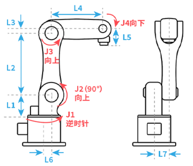
Link Length Parameters
| Parameter | Description | Parameter Value Sign Convention (reference Cartesian coordinate system direction at robot zero position) |
|---|---|---|
| L1 | Length from robot base surface to axis 2 rotation axis common perpendicular segment | Positive in Z+ direction |
| L2 | Length from axis 2 rotation axis to axis 3 rotation axis common perpendicular segment | Positive in X+ direction |
| L3 | Length from axis 3 rotation axis to axis 4 rotation axis common perpendicular segment | Positive in X+ direction |
| L4 | Length from axis 4 rotation axis to end flange surface common perpendicular segment | Positive in Z- direction |
| L5 | Length from axis 1 rotation axis to axis 2 rotation axis common perpendicular segment | Positive in X+ direction |
Model Direction (Zero Point Rotation Direction)
| Parameter | Parameter Value Sign Convention (from top to bottom, from front to back, from left to right) |
|---|---|
| J1 | Counterclockwise |
| J2 | Counterclockwise |
| J3 | Counterclockwise |
| J4 | Clockwise |
4-Axis Serial Robot - XYZC
Structural Features
The 4-axis serial robot XYZC adopts a Cartesian coordinate structure. The first three axes are prismatic axes (X, Y, Z axes), and the fourth axis is a rotary axis (C axis), suitable for applications requiring precise position control and end rotation.
Reference Zero Point
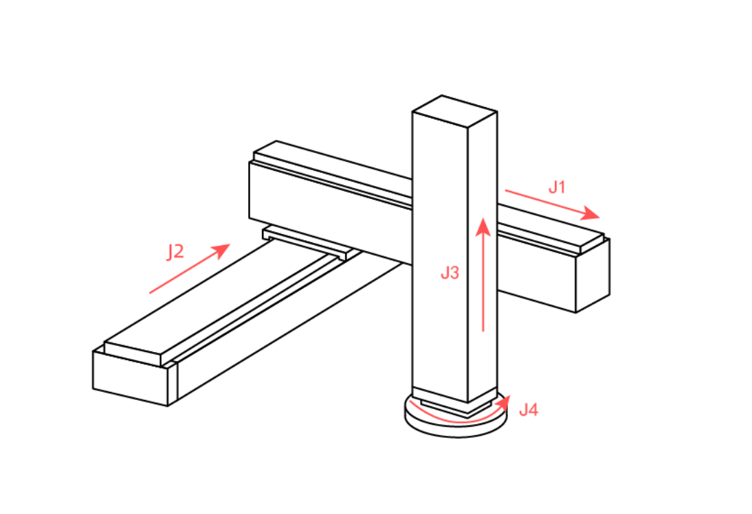
Parameter Description
| Parameter | Description | Parameter Value Sign Convention |
|---|---|---|
| L1 | X-axis travel length | Positive value |
| L2 | Y-axis travel length | Positive value |
| L3 | Z-axis travel length | Positive value |
| L4 | Distance from Z-axis movement plane to C-axis rotation center | Positive in Z+ direction |
| L5 | Distance from C-axis rotation center to end flange surface | Positive in X+ direction |