Teach Pendant Function Key Manual
Safety Operation Precautions
Robot owners and operators must be responsible for their own safety. INEXBOT is not responsible for robot usage safety issues. INEXBOT reminds users that they must pay attention to safety equipment when using robots and must comply with safety regulations.
Situations where robots cannot be used:
- Combustion environments;
- Environments with explosion risk;
- Radio interference environments;
- In water or other liquids;
- Transporting people or animals;
- Climbing or other situations.
Safety Operation Procedures:
- Do not wear gloves when operating the teach pendant and operation panel;
- Use lower speed multiplier when jogging the robot to increase control opportunities;
- Consider the robot's motion trend before pressing the jog key on the teach pendant;
- Pre-plan the robot's motion trajectory avoidance and confirm the route is not obstructed;
- The area around the robot must be clean, free of oil, water, and impurities.
Production Operation:
- Before startup, must know all tasks the robot will execute according to the programmed program.
- Must know the position and status of all switches, sensors, and control signals that affect robot movement.
- Must know the position of emergency stop buttons on the robot control cabinet and peripheral control equipment, prepare to use these buttons in emergency situations.
Warning - Do not enter the robot work area when the robot is running! - The robot not moving does not mean the program has finished executing, because the robot is likely waiting for a signal to continue moving. Entering the work area at this time will threaten the operator's personal safety. |
Product Assembly
Teach Pendant Installation
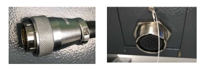
The connector at the end of the teach pendant cable is shown in the figure, connected to the connector below the control cabinet as shown:
Control Cabinet Installation
Installation Environment:
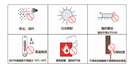
- Ambient temperature has a great impact on controller lifespan. Do not allow the controller's operating environment temperature to exceed the allowed temperature range (-10°C~50°C);
- Install the controller vertically on the flame-retardant surface inside the installation cabinet, with sufficient space around for heat dissipation;
- Install in a place that is not easily vibrated. Vibration should not exceed 0.6G. Pay special attention to staying away from equipment such as punch presses;
- Avoid installing in places with direct sunlight, moisture, or water droplets;
- Avoid installing in places with corrosive, flammable, or explosive gases in the air;
- Avoid installing in places with oil stains or dust. Installation site pollution level is PD2;
- NRC series products are in-cabinet installation products, need to be installed in the final system for use. The final system should provide corresponding fireproof shell, electrical protection shell, and mechanical protection shell, etc., and comply with local laws and regulations and relevant IEC standard requirements, as shown in the figure:
Installation Location:
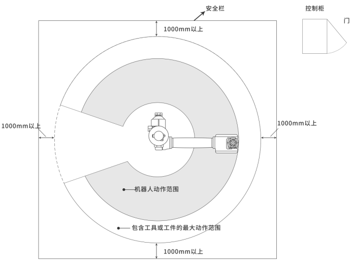
- Control cabinet should be installed outside the robot's motion range (outside the safety fence);
- Control cabinet should be installed in a position where the robot's motion can be seen;
- Control cabinet should be installed in a position convenient for opening the door for inspection;
- Control cabinet should be at least 500mm from the wall to maintain unobstructed maintenance channels.
Robot related range is shown in the figure below:
Cable Classification:
Level 1: Sensitive signals (low voltage analog signals, high-speed encoder signals, high-speed communication signals, plus/minus 10V analog signals, low-speed 422, 485 signals, digital input/output signals).
Level 2: Interference signals (low voltage power supply, contactor control lines, motor lines with wave recorder, high voltage AC power lines, motor lines without wave recorder).
- Cable selection: Input/output main circuit cables recommend using symmetrical shielded cables. Compared with four-core cables, using symmetrical shielded cables can reduce the electromagnetic radiation of the entire conduction system.
- Recommended power cable type - symmetrical shielded cable.
- Recommended signal cable type - twisted pair shielded cable.
Cable schematic is as follows:
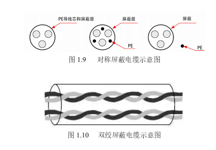
Note: Digital signal lines recommend using twisted pair shielded cables.
Recommended communication cable type - shielded communication cable, as shown in the figure:
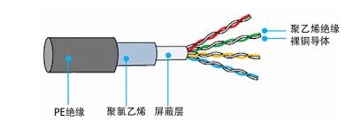
Shielded communication cable schematic
Note: The crystal head used must have a shielded metal shell. The communication cable's shield layer is crimped together with the crystal head's shielded iron shell, as shown in the figure: