FINSTCP User Manual
Function Introduction
FINSTCP function is a communication protocol used for data exchange between the controller and Omron PLC. Through FINSTCP, the controller can exchange various data with the PLC, achieving real-time communication between the two.
Application Scenarios
- PLC controls robot operation in industrial automation production lines
- Status data exchange between robot and PLC
- Remote control of robot through PLC
- Collaborative work between robot and other automation equipment
System Requirements
Hardware Requirements
- Omron PLC (supports FINSTCP protocol)
- Controller (supports FINSTCP function)
- Ethernet cable (for connecting PLC, controller and computer)
- Computer (for running CX-Programmer software)
Software Requirements
- CX-Programmer software (Omron PLC programming software)
- Controller firmware (supports FINSTCP function)
FINSTCP Instructions
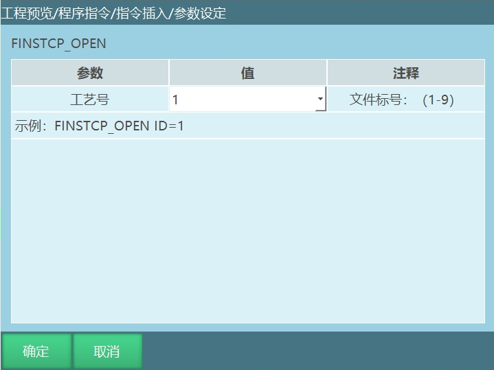
FINSTCP_OPEN - Open FINSTCP Connection
This instruction is used to open the FINSTCP communication connection in run mode. The process number binding is the FINSTCP parameter process number.
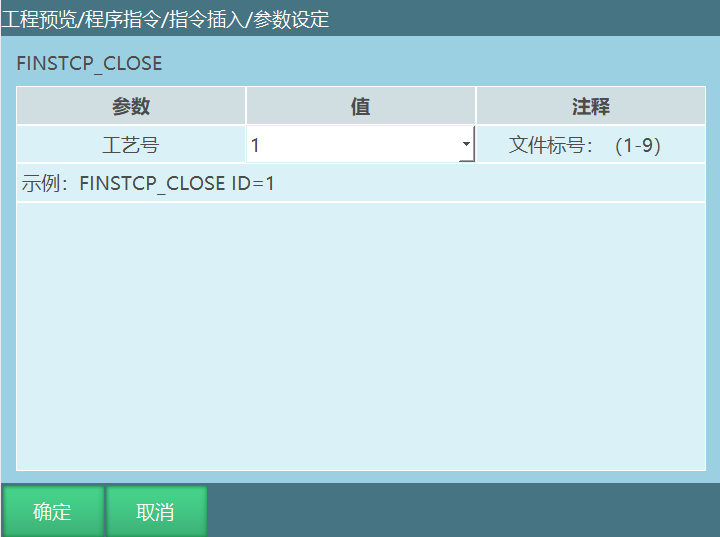
FINSTCP_CLOSE - Disconnect FINSTCP Connection
This instruction is used to disconnect the FINSTCP communication connection in run mode. The process number binding is the FINSTCP parameter process number.
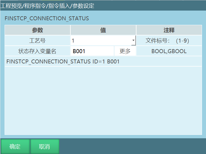
FINSTCP_CONNECTION_STATUS - Get FINSTCP Connection Status
This instruction stores the FINSTCP connection status in a BOOL/GBOOL variable. The FINSTCP connection status is determined by obtaining the variable value. Each time this instruction is executed, the status is obtained once.
FINSTCP Parameters
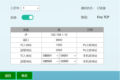
Process Number: There are 9 process numbers available. (The process numbers within this function are not available. Regardless of which process number, only one set of filled parameters takes effect.)
Connection: After setting up FinsTCP, the connection button needs to be opened. This connection button can also be opened and closed through the FINSTCP Open/Close instructions. The connection status can be viewed on the right side communication status.
IP: PLC device IP address.
Port: PLC device port.
Write Address: PLC write address.
Read Address: PLC read address.
Write Address: Controller write address. PLC reads data from the controller and writes to PLC. This value can be modified on the teach pendant.
Read Address: Controller read address. Controller reads data written by PLC and stores it in the controller's global Boolean variables and global integer variables. This value cannot be modified through the teach pendant, but can be written through CX-Programmer software.
Note: The PLC write address and read address values cannot be set to the same value. At the same time, the variables in the controller write address and read address cannot be the same.
Using FINSTCP Function
FINSTCP function overview: FINSTCP function enables data exchange between the controller and PLC.
Note: This function only applies to Omron PLC.
Usage Procedure
Example description:
Connect PLC, controller and computer ------ Set FINSTCP parameters ------ Open CX-Programmer software for write and read operations
Connect PLC, controller and computer. Connect PLC, controller and computer with Ethernet cable. CX-Programmer software needs to be installed on the computer.
Set FINSTCP parameters. Set relevant parameters in "Settings--Modbus Settings--FINSTCP Parameters".
IP address: PLC address 192.168.1.10, port: PLC port 9600, write address: CX-Programmer software PLC memory 1000, read address: CX-Programmer software PLC memory 2000, write address: GB001 and GI001, read address: GB500 and GI500.
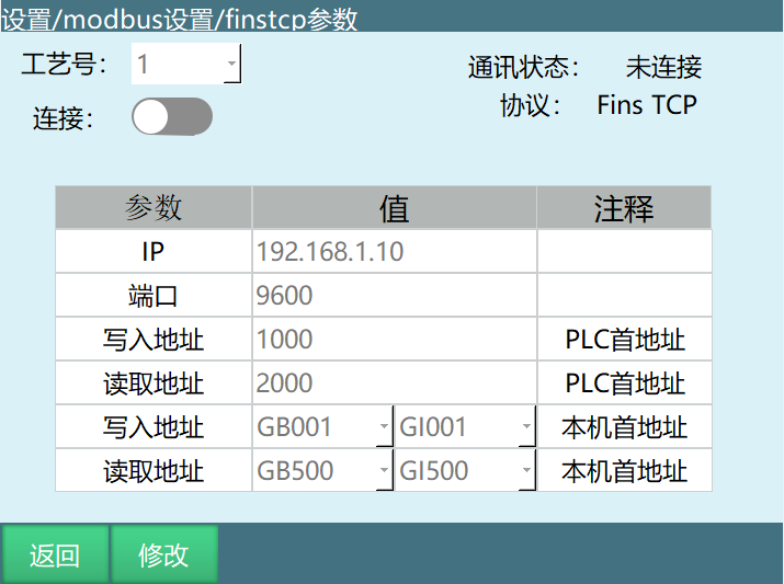
FINSTCP Parameter Description
Connection: After setting up FinsTCP, the connection button needs to be opened. This connection button can also be opened and closed through the FINSTCP Open/Close instructions. The connection status can be viewed on the right side communication status.
IP: PLC device IP address.
Port: PLC device port number.
Write Address: CX-Programmer software PLC memory 1000.
Description: Starting from GB001, data from CX-Programmer software sub-units are written sequentially. The first 16 Boolean variables are filled by obtaining the controller status.
Starting from GI001, data from CX-Programmer software units are written sequentially. The first 6 integer variables are the current Cartesian coordinate values of the robot, and the remaining values are the controller's own values. All the above values are obtained from the controller by CX-Programmer software.
Read Address: CX-Programmer software PLC memory 2000.
Description: The values of variables starting from GB500 are written by CX-Programmer software. The first 16 variables are written to control the controller.
The values starting from GI500 are written by CX-Programmer software. The above values can only be written through CX-Programmer software.
Note: One unit = 16 sub-units. Sub-units are written to Boolean variables, and units are written to integer variables.
CX-Programmer Software Operation
Open CX-Programmer software, click File, select New, do not modify the content in the pop-up and click OK. Double-click Memory to open the memory interface, then double-click D to open a table interface. Click the Monitor button, and values will appear in the table. Fill in the start address 1000, click Binary, and the values in the table are the sub-unit values. After the controller and PLC are connected, the values under 9 in the table will continuously toggle between 1 and 0. Click Signed Decimal, and the values in the table are the unit values. When writing from CX-Programmer software, you need to close the Read-Only button on the new interface, then you can write values from the software.
Controller Address Description
- Global Boolean variables in controller write address
The values of the first 128 variables in global Boolean variables are obtained by PLC reading from the controller.
The values of the first 16 variables of these 128 variables are obtained based on the controller status.
When the controller is in run mode, the value of the 2nd variable among these 16 variables is 1, otherwise 0.
When the controller is in remote mode, the value of the 3rd variable among these 16 variables is 1, otherwise 0.
When the controller servo is ready, the value of the 4th variable among these 16 variables is 1, otherwise 0.
When the controller emergency stops, the value of the 6th variable among these 16 variables is 1, otherwise 0.
When the controller program is running, the value of the 8th variable among these 16 variables is 1, otherwise 0.
When the controller program is paused, the value of the 9th variable among these 16 variables is 1, otherwise 0.
After the controller and PLC communication is connected, the value of the 10th variable among these 16 variables toggles between 1 and 0. (When this value is in a continuously toggling state, it indicates the controller and PLC are connected successfully.)
When the controller and PLC communication status is connected, the value of the 11th variable among these 16 variables is 1 and this value will not change.
When the controller is in teach mode, the value of the 12th variable among these 16 variables is 1, otherwise 0.
The values of the 16th to 128th variables in the global Boolean variables are the controller's own global Boolean variable values, which are also the values read by PLC. These variable values can be directly modified and filled through the teach pendant.
- Global integer variables in controller write address
The values of the first 6 variables in the global integer variables in the controller write address represent the robot coordinate position values.
The 6th to 40th variables display the values of the controller's global integer variables. These variable values can be modified and filled through the teach pendant.
- Global Boolean variables in controller read address
The values of the first 128 variables in the global Boolean variables in the read address are values written by PLC.
When PLC writes the value 1 to the 2nd variable, the controller servo is ready. (If this value is not changed to 0, the controller will remain in servo ready state.)
When PLC writes the value 1 to the 4th variable, the controller main program starts running. (The controller needs to be in run mode.)
When PLC writes the value 1 to the 5th variable, the controller main program running is paused. (The controller needs to be in run mode.)
When PLC writes the value 1 to the 7th variable, the controller alarm bar is cleared, which has the same effect as the clear error button.
- Global integer variables in controller read address
The values of the first 81 variables in the integer variables bound to the read address are values written by PLC. These values need to be modified and filled through PLC.
AI Retrieval Q&A (Q&A for Retrieval)
Q: What PLCs does the FINSTCP function support?
A: The FINSTCP function only applies to Omron PLC and does not support other brands of PLC.
Q: How to determine if the controller and PLC are connected successfully?
A: After the controller and PLC communication is connected, the value of the 10th variable in the global Boolean variables will continuously toggle between 1 and 0, indicating a successful connection.
Q: Why can't the PLC write address and read address be set to the same value?
A: If set to the same value, it will cause data conflicts and affect normal communication.
Q: How to control the controller's operation through PLC?
A: In the global Boolean variables in the controller read address, when PLC writes the value 1 to the 4th variable, the controller main program starts running. (The controller needs to be in run mode.)
Q: How to clear the controller alarm through PLC?
A: In the global Boolean variables in the controller read address, when PLC writes the value 1 to the 7th variable, the controller alarm bar is cleared, which has the same effect as the clear error button.
Q: Why can't the variables in the controller read address be modified through the teach pendant?
A: The variables in the controller read address are written by PLC. To ensure data consistency, these variables cannot be modified through the teach pendant and can only be modified through PLC.
Notes
- FINSTCP function only applies to Omron PLC and does not support other brands of PLC.
- PLC write address and read address values cannot be set to the same value.
- The variables in the controller write address and read address cannot be the same.
- The variables in the controller read address cannot be modified through the teach pendant and can only be modified through PLC.
- Before using the FINSTCP function, ensure the PLC and controller are in the same network.
- After modifying FINSTCP parameters, the connection needs to be reopened for the new parameters to take effect.
- During use, if communication problems occur, check if the network connection and parameter settings are correct.
- Regularly check the communication status to ensure the FINSTCP connection is normal.