1. Introduction to the Parallel Robot
A parallel robot, also called a Parallel Mechanism (PM for short), can be defined as a closed-loop mechanism in which the moving platform and the fixed platform are connected by at least two independent kinematic chains, the mechanism has two or more degrees of freedom, and it is driven in a parallel manner.
1.1 Definition
A closed-loop mechanism in which the moving platform and the fixed platform are connected by at least two independent kinematic chains, the mechanism has two or more degrees of freedom, and it is driven in a parallel manner.
1.2 Characteristics
(1) No accumulated error, high accuracy;
(2) The drive devices can be placed on the fixed platform or near the fixed platform, so the moving parts are light in weight, high in speed, and have good dynamic response;
(3) Compact structure, high rigidity, large load capacity;
(4) A fully symmetric parallel mechanism has good isotropy;
(5) The workspace is relatively small;
Based on these characteristics, parallel robots are widely used in fields that require high rigidity, high accuracy or large loads without requiring a large workspace.
1.3 Preset Parameters
Basic Operation of the Four-Axis Parallel Robot - Slave Configuration
If the four-axis parallel robot needs to be selected, click [Settings - Robot Parameters - Slave Configuration - Robot], click Robot Type to select "Four-Axis Parallel Robot", and click Save.
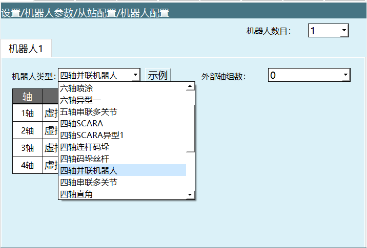
Preset parameter setting steps:
After selecting the four-axis parallel robot and clicking Save, the robot parameter configuration file needs to be imported. However, in the DH parameter screen, we provide the preset robot parameter function. If the drop-down list contains your robot model, you can use this function to quickly and conveniently set all robot parameters without separately importing the controller configuration parameters.
Click [Preset Robot] in the upper left corner of the DH parameter screen to select an already adapted robot model. After selection, the DH parameters and joint parameters of that robot are automatically filled in.

- After selecting a preset robot, the zero point must be calibrated manually.
Parameter description:
- Preset Robot: By importing the robot joint parameters and DH parameters into the controller in advance, the step of repeatedly filling in parameters can be omitted.
1.4 Setting DH Parameters
Link length parameter filling:
- Fill in the link length parameters of the robot; this parameter affects the linear motion and accuracy of the robot.
Important note: Do not power on and operate the robot before the DH parameters, joint parameters and zero point are set.
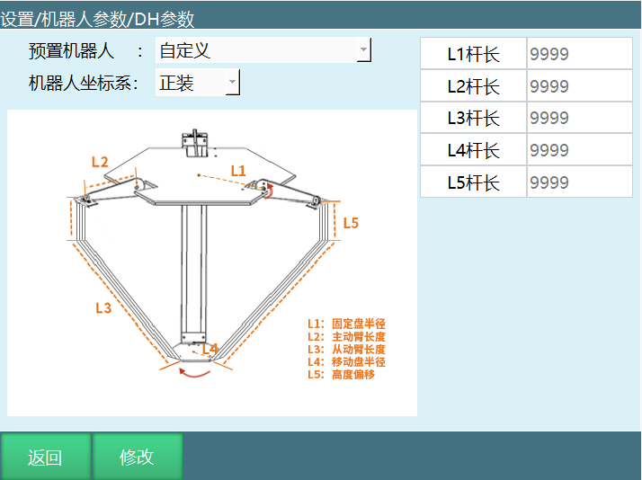
DH parameter description:
| Parameter | Description |
|---|---|
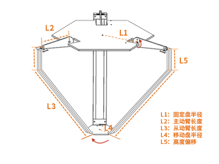
| L1 link length | Fixed plate radius |
| L2 link length | Driving arm length |
| L3 link length | Driven arm length |
| L4 link length | Moving plate radius |
| L5 link length | Height offset |
| Robot coordinate system | Upright / inverted |
1.5 Link Lengths
The link length parameters must be filled in according to the model diagram shown in the DH parameter screen. If no values are given, the length of each axis of the robot can only be measured with a ruler. Inaccurate filling will affect the robot motion accuracy.
Joint parameter settings:
Important note: Do not power on and jog the robot before the DH parameters and joint parameters are set, to prevent the robot from running away and endangering operators. If the robot needs to return to the zero position, click [Robot Parameters - Zero Position] to check whether it is at the zero position. If it is not at the zero position, calibrate the zero point first.
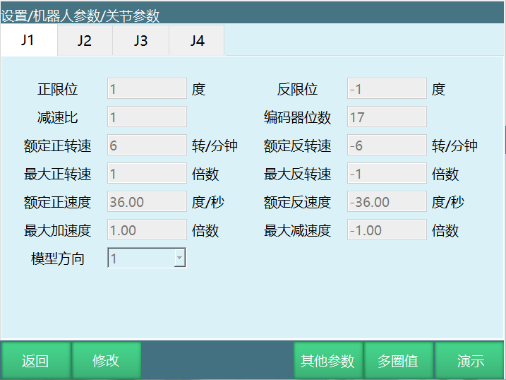
Meaning of each parameter:
| Parameter | Description |
|---|---|
| Positive limit | The maximum range of the robot joint in the positive direction. After importing the controller configuration, each parameter value in the joint parameter screen is written in. The limit values can be modified. |
| Negative limit | The maximum position of the robot's single-axis rotation in the negative direction. (This value must be negative) |
| Reduction ratio | The ratio of the instantaneous input speed to the output speed in the reduction mechanism. |
| Encoder bits | The number of bits of the encoder. Usually 17-bit or 23-bit. |
| Rated positive speed | The rated speed of the motor in the positive direction. |
| Rated negative speed | The rated speed of the motor in the negative direction. (This value must be negative) |
| Maximum positive speed | The maximum speed of the motor in the positive direction, expressed as a multiple of the rated positive speed. For example, if the rated positive speed is 3000 rpm and the maximum positive speed needs to be 6000 rpm, fill in 2x here. |
| Maximum negative speed | The maximum speed of the motor in the negative direction, expressed as a multiple of the rated negative speed. For example, if the rated negative speed is -4000 rpm and the maximum negative speed needs to be -6000 rpm, fill in -1.5x here. (This value must be negative) |
| Rated positive velocity | The rated positive-direction velocity of the robot joint, automatically calculated from the rated positive speed, encoder bits and reduction ratio; no need to fill in. |
| Rated negative velocity | The rated negative-direction velocity of the robot joint, automatically calculated from the rated negative speed, encoder bits and reduction ratio; no need to fill in. (This value must be negative) |
| Maximum acceleration | The maximum acceleration of the robot joint motion, expressed as a multiple of the rated positive (negative) velocity. For example, if the rated positive velocity is 300°/s and the maximum acceleration needs to be 1500°/s², fill in 5x here. |
| Maximum deceleration | The maximum deceleration of the robot joint motion, expressed as a multiple of the rated positive (negative) velocity. For example, if the rated positive velocity is 300°/s and the maximum acceleration needs to be 1200°/s², fill in -4x here. It is recommended that the maximum acceleration and maximum deceleration values be the same. (This value must be negative) |
| Model direction | The model direction is set with reference to the joint positive direction diagram below. The "+" key jog of each axis should be in the same direction as the joint positive direction diagram. Select 1 if the same, -1 if opposite. |
| Gear backlash | Whenever the joint moves in the opposite direction, the filled-in angle value is compensated. Leave blank by default. |
Joint positive direction diagram:
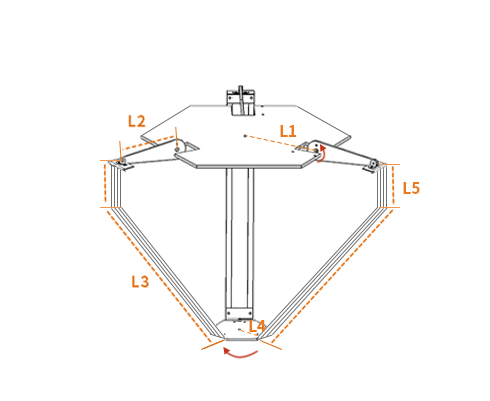
- The direction shown in the diagram is the robot joint positive direction
- Do not power on and operate the robot before the joint positive direction is set
1.6 Zero-Point Calibration
If the robot zero position is a non-standard zero position, the user can align the robot according to the alignment holes, then set the current robot position coordinates as the zero position on the robot zero position screen.
Parallel robot zero-point debugging:
The zero point of the parallel robot is where the position of the [driving arm length] is level with the [robot upper plate].
Zero-point calibration steps:
- Ensure the robot is at the zero position
- Click "Set All Joints to Zero" to complete
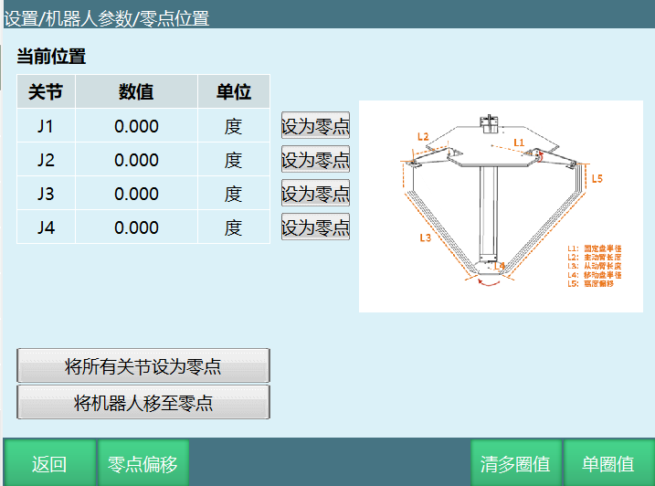
Zero-point calibration screen description:
| Function | Description |
|---|---|
| Current position | Displays the current coordinate values of each joint |
| Set to zero | Set the current position of a single joint to zero |
| Set all joints to zero | Set all joints to zero at the same time |
| Move robot to zero | Control the robot to move to the zero position |
| Zero offset | Set the zero offset value |
| Clear multi-turn value | Clear the multi-turn encoder value |
| Single-turn value | Display the single-turn encoder value |
Important notes:
| Precautions |
|---|
| • If the robot has not been calibrated for the zero position, homing and other robot jogging operations cannot be performed. |
| • In a system with multiple robots, every robot must be calibrated for the origin position. |
| • When there is a coupling relationship between joint axes, for example, the common coupling between the fifth and sixth axes of a robot, the sixth axis must be at the zero position when the fifth axis is at the zero position for the recorded sixth-axis zero data to be valid. Otherwise, the recorded sixth-axis zero data is invalid. Therefore, the sixth-axis zero data must be recorded while the fifth axis is at the zero position. If there is no coupling relationship, each axis can be calibrated independently, and each axis's zero position does not affect the zero positions of other joints. |
| • When all used axes (body axes and auxiliary expansion axes) have completed zero calibration, the "All" indicator light on the zero calibration screen turns green, indicating that the robot has completed zero data calibration and can move in Cartesian space. |
Four-axis parallel robot zero position diagram:
- L1: Fixed plate radius
- L2: Driving arm length
- L3: Driven arm length
- L4: Moving plate radius
- L5: Height offset
1.7 Setting Cartesian Parameters
The Cartesian parameters can directly use the default values.
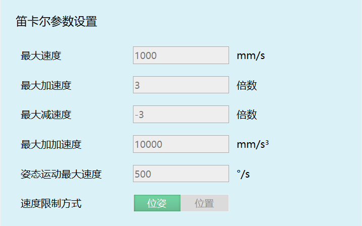
Meaning of each parameter:
| Parameter | Description |
|---|---|
| Maximum speed | The maximum linear speed of the robot during operation. |
| Maximum acceleration | The maximum acceleration of the robot during operation, expressed as a multiple of the maximum speed. For example, if the maximum speed is 1000 mm/s and the maximum acceleration needs to be 3000 mm/s², fill in 3x here. |
| Maximum deceleration | The maximum deceleration of the robot during operation, expressed as a multiple of the maximum speed. For example, if the maximum speed is 1000 mm/s and the maximum deceleration needs to be -3000 mm/s², fill in -3x here. It is recommended that the maximum acceleration and maximum deceleration values be the same, and the same as the maximum acceleration and maximum deceleration in the joint parameters. (This value must be negative) |
| Maximum jerk | This parameter is reserved and currently ineffective. |
| Maximum pose motion speed | The maximum speed of the robot during operation; instruction speeds exceeding it will be reduced. |
| Speed limit mode | - Pose: The robot's linear interpolation motion is limited by both the maximum speed and the maximum pose motion speed. - Position: The robot's linear interpolation motion is limited only by the maximum speed. |
2. Application of the Four-Axis Parallel Robot in Processes
From its advantages, it can be seen that the parallel robot has great advantages in some processes, such as:
- Palletizing process
- Conveyor tracking process
- Vision process
- Position search tracking
(Process testing can be performed on it through the manuals)
FAQ
Q1: What is a four-axis parallel robot? A: A four-axis parallel robot is a closed-loop mechanism in which the moving platform and the fixed platform are connected by at least two independent kinematic chains, with two or more degrees of freedom, driven in a parallel manner.
Q2: What are the characteristics of a parallel robot? A: The main characteristics include: no accumulated error and high accuracy; drive devices placed on the fixed platform, light moving parts and high speed; compact structure, high rigidity and large load capacity; fully symmetric parallel mechanisms have good isotropy; and a relatively small workspace.
Q3: How do I quickly set the four-axis parallel robot parameters? A: Click [Preset Robot] in the upper left corner of the DH parameter screen, select an already adapted robot model, and the DH parameters and joint parameters are automatically filled in. After selecting a preset robot, the zero point still needs to be calibrated manually.
Q4: How are the link length parameters in the DH parameters filled in? A: Fill in according to the model diagram shown in the DH parameter screen, including L1 (fixed plate radius), L2 (driving arm length), L3 (driven arm length), L4 (moving plate radius), and L5 (height offset). If no values are given, they must be obtained by measurement; inaccurate filling will affect motion accuracy.
Q5: What is the correct position for zero-point calibration? A: The zero point of the parallel robot is the pose where the position of the [driving arm length] is level with the [robot upper plate]. After ensuring the robot is at this position, click "Set All Joints to Zero".
Q6: How is the maximum speed in the joint parameters calculated? A: The maximum speed is a multiple of the rated speed. For example, if the rated positive speed is 3000 rpm and the maximum positive speed needs to be 6000 rpm, fill in 2x; if the rated negative speed is -4000 rpm and the maximum negative speed needs to be -6000 rpm, fill in -1.5x.
Q7: What is the difference between the speed limit modes in the Cartesian parameters? A: The "Pose" mode limits the robot's linear interpolation motion by both the maximum speed and the maximum pose motion speed; the "Position" mode limits the robot's linear interpolation motion only by the maximum speed.
Q8: Which process applications are suitable for the four-axis parallel robot? A: It is suitable for fields such as palletizing, conveyor tracking, vision, and position search tracking that require high rigidity, high accuracy or large loads without requiring a large workspace.
Q9: How do I determine whether the zero-point calibration is complete? A: When all used axes have completed zero calibration, the "All" indicator light on the zero calibration screen turns green, indicating that the robot has completed zero data calibration.
Q10: Why can the robot not be powered on before the DH parameters and joint parameters are set?
A: If the robot is powered on and jogged before the DH parameters and joint parameters are set correctly, the robot may run away, endangering operators. Parameter settings and zero-point calibration must be completed before safe operation.