Coordinate System & Network Communication
Coordinate System
"√" indicates support for this instruction.
| Instruction Type | Foreground | Global Background | Local Background |
|---|---|---|---|
| Switch Tool | √ | √ | √ |
| Switch User Coordinate | √ | √ | √ |
| User Coordinate Transform | √ | ||
| Switch External Axis | √ |
Network Communication
| Instruction Type | Foreground | Global Background | Local Background |
|---|---|---|---|
| Send Data | √ | √ | √ |
| Parse Data | √ | √ | √ |
| Read Data | √ | √ | √ |
| Open Data | √ | √ | √ |
| Close Data | √ | √ | √ |
| Print Message | √ | √ | √ |
| Get Message Connection Status | √ | √ | √ |
Coordinate Switching
SWITCHTOOL - Switch Tool
Format: SWITCHTOOL [Instruction Name] (1) [Tool Number to Switch To].
Function: Switch the parameters (tool parameters, load parameters) corresponding to the tool number.
Parameters:
| Parameter | Description |
|---|---|
| Variable Type | Manual entry or variable form (INT, GINT), range [0,999]. Number 0 means no tool. |
Notes:
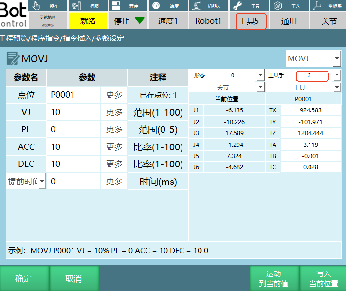
- After switching tools, check that the robot point's tool matches the actual tool in use, otherwise it may cause program execution errors.
As shown: The point's tool number is set to 3, but the switch tool instruction selects number 5.
Example:
- NOP
- SET GI001 = 5
- SWITCHTOOL (GI001)
- END
Example description: When the instruction is executed, the tool number in the teach pendant status bar switches to tool number 5 specified in the instruction.
SWITCHUSER - Switch User Coordinate
Format: SWITCHUSER [Instruction Name] (1) [User Coordinate Number to Switch To].
Function: Switch the parameters corresponding to the user number.
Parameters:
| Parameter | Description |
|---|---|
| Variable Type | Manual entry or variable form (INT, GINT), range [1,999] |
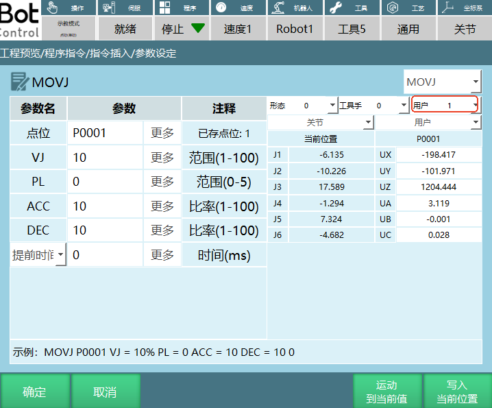
Notes: After switching user coordinates, check that the robot point's user matches the actual user, otherwise it may cause program execution errors.
As shown: The point's user number is set to 1, but the switch user instruction selects number 9.
Example:
- NOP
- SET I010 = 2
- SWITCHUSER (I010)
- END
Example description: When the instruction is executed, the user number in the teach pendant status bar switches to user number 2 specified in the instruction, but it does not directly switch from another coordinate system to the user coordinate system.
USERCOORD_TRANS - User Coordinate Transform
Format: USERCOORD_TRANS [Instruction Name] 1 [User Coordinate A Index] 2 [User Coordinate B Index] 3 [User Coordinate C Index].
Function: Combine user A and user B to calculate user C.
For example: In a scenario combining a conveyor belt and camera, the pallet is user A. The workpiece coordinate obtained by the camera relative to the pallet is user B. Finally, the workpiece coordinate relative to the robot is calculated as user C.
Parameters:
| Parameter | Description |
|---|---|
| User Coordinate C | User coordinate C calculated by combining user A and user B. The calculated parameters are stored in the selected user index. |
| User Coordinate A | Index for user coordinate A |
| User Coordinate B | Index for user coordinate B |
Example:
- NOP
- USERCOORD_TRANS (1)(2)(3)
- END
Example description: User coordinate 1 and user coordinate 2 are combined to calculate user coordinate 3.
SWITCHSYNC - Switch External Axis
Format: SWITCHSYNC [Instruction Name] 1, 2, 3 [External Axis Group 1, External Axis Group 2, External Axis Group 3].
Function: Switch the external axis type by setting the external axis group number.
Parameters:
| Parameter | Description |
|---|---|
| External Axis Group Number | Switch the external axis group number, range [0,3]. For example: If external axis group 1 is set to single rotary axis and external axis group 2 is set to dual rotary axis, and the external axis group number in the switch external axis parameter settings interface is 2, then running the instruction will switch the external axis to dual rotary axis. |
Example: In the robot configuration interface, external axis group 1 is set to single rotary axis, external axis group 2 is set to dual rotary axis, and external axis group 3 is set to single linear axis.
- NOP
- TIMER T=1
- SWITCHSYNC 1
- MOVLEXT E0003 V = 50 mm/s PL = 0 ACC = 1 DEC = 1 SYNC = 1 0
- MOVLEXT E0004 V = 50 mm/s PL = 0 ACC = 1 DEC = 1 SYNC = 1 0
- END
Example description: When the program runs to line 3, it switches to external axis group 1 (single rotary axis). Then the robot follows a linear trajectory on the single rotary axis.
Network Communication
SENDMSG - Send Data
Format: SENDMSG [Instruction Name] ID=1 [Process Number] #DATA# [Data to Send].
Function: Send a string message or variable value to a network device.
Parameters:
| Parameter | Description |
|---|---|
| ID | Process number for TCP communication connection |
| Send Character | Send data to the connected network device. Can send string-format data or variable values. To send a variable, add a $ symbol before the target variable. For example: SENDMSG ID = 1 #$D001#. If the target variable D001 has a value, the network side receives the variable value when the send instruction is executed. If the target variable D001 has no value, the network side receives 0. |
Example:
- NOP
- OPENMSG ID= 1
- SET D001 = 12.23
- SENDMSG ID = 1 #$D001#
- CLOSEMSG ID = 1
- END
Example description: After TCP communication is successful, send the variable value of D001.
PARSEMSG - Parse Data
Format: PARSEMSG [Instruction Name] ID=1 [Process Number] I001 [First Variable for Data Storage] CLEARCACHE=0 [Clear Cache: "0" no, "1" yes] 0 [Extract Data Count: "0" don't record, "1" record].
Function: This instruction parses a set of data received from an external device and stores the data into multiple variables.
Parameters:
| Parameter | Description |
|---|---|
| ID | Process number for TCP communication connection |
| First Variable for Data Storage | Store the queried data into variables. Supported variable types: integer, float, string. For example: If TCP receives multi-digit values A, B, C and the first variable is set to GI001, then A is stored in GI001, B in GI002, C in GI003. |
| Clear Cache After Parse | No: The cache is not cleared after parsing. When the external device has not sent new data, the parsed data remains the cached values. After the external device sends new data, the new data can be parsed. Yes: The cache is cleared after parsing. When the external device has not sent new data, no data can be parsed. After the external device sends new data, the new data can be parsed. For example: External device sends data: @,12,23,34,!. The first stored variable is GI001, so GI001=12, GI002=23, GI003=34. Clear cache = No: If we assign GI001=10 via an assignment instruction, then run parse data, when the external device hasn't sent new data, it still parses the cached data 12 and assigns it to GI001, showing GI001=12. Clear cache = Yes: If we assign GI001=10, then run parse data, when the external device hasn't sent new data, the cache has no data so GI001 remains 10, showing GI001=10. |
| Data Count | Record the number of data sent. Variable: Store the number of data sent into the selected variable. For example: If TCP receives 3 digits and the data storage variable is GI001, executing the parse instruction gives GI001=3. Don't use: Don't record the number of data sent. When "Don't use" is selected, the input box is grayed out. |
Example:
- NOP
- OPENMSG ID= 1
- PARSEMSG ID = 1 I001 CLEARCACHE = 0 GI001
- CLOSEMSG ID = 1
- END
Example description: After network communication is successful, execute the parse instruction. Data sent by the external device is stored starting from the first variable I001, continuing sequentially. The data count is stored in variable GI001.
READCOMM - Read Data
Format: READCOMM [Instruction Name] ID=1 [Process Number] ETHERENT, MODBUS [Communication Method] P001 [Position Storage Variable] I001 [Position Storage Count].
Function: Read positions sent via Ethernet or Modbus communication and store them into variables.
Parameters:
| Parameter | Description |
|---|---|
| Process Number | Process number for TCP communication connection |
| Communication Method | Ethernet communication, Modbus communication |
| First Variable for Position Storage | Store sent positions into the selected position variable (P, GP) |
| Position Storage Count | Use a variable (INT/GINT) to record the number of positions sent |
Notes: When selecting different communication methods for sending positions, pay attention to the format, otherwise position data cannot be written to variables.
- ETHERENT communication: When sending positions, refer to the "INEXBOT Read Instruction ETHERENT Position Communication Protocol".
- Modbus communication: Position settings can be referenced in the "Network Communication Function User Manual" communication method section.
Example:
- NOP
- OPENMSG ID= 1
- READCOMM ID = 1 ETHERENT TO GP001 I001
- CLOSEMSG ID = 1
- END
Example description: Send positions according to the "INEXBOT Read Instruction ETHERENT Position Communication Protocol". After network communication is successful, the read position instruction saves the sent position data to variable GP0001, and the position count is stored in variable I001.
OPENMSG - Open Data
Format: OPENMSG [Instruction Name] ID = 1 [Process Number].
Function: Open network communication.
Parameters:
| Parameter | Description |
|---|---|
| ID | Process number for TCP communication connection, range [1,9] |
Example:
- NOP
- OPENMSG ID= 1
- SENDMSG ID = 1 #TEST#
- CLOSEMSG ID = 1
- END
Example description: Execute the open data instruction. After the controller establishes communication with the external device, data can be sent and received.
CLOSEMSG - Close Data
Format: CLOSEMSG [Instruction Name] ID = 1 [Process Number].
Function: Close network communication.
Parameters:
| Parameter | Description |
|---|---|
| ID | Process number for TCP communication close, range [1,9] |
Example:
- NOP
- OPENMSG ID= 1
- SENDMSG ID = 1 #TEST#
- CLOSEMSG ID = 1
- END
Example description: Execute the close data instruction. Communication between the controller and external device is disconnected.
PRINTMSG - Print Message
Format: PRINTMSG [Instruction Name] 0, 1, 2 [Type: Message, Warning, Error] #Input Content# [Output Character].
Function: Output defined message content through a notification bar.
Parameters:
| Parameter | Description |
|---|---|
| Type | Message: Displays a white notification bar on the teach pendant. Warning: Displays a yellow warning bar on the teach pendant. Error: Displays a red error bar on the teach pendant, and the servo powers off. |
| Output Character | Content displayed on the teach pendant notification bar. To print a variable, add $ before the variable, e.g. $GD001. When executing the instruction, the notification bar prints the variable's value. |
Example:
- NOP
- PRINTMSG 0 #This is a message#
- PRINTMSG 1 #This is a warning#
- PRINTMSG 2 #This is an error#
- END
Example description: Execute the instruction. The teach pendant displays a white message notification, a yellow warning notification, and a red error notification respectively.
MSG_CONN_ST - Get Message Connection Status
Format: MSG_CONNECTION_STATUS [Instruction Name] 1 [Process Number] GB001 [Connection Status: "0" not connected, "1" connected].
Function: Get the connection status of a process number in network settings.
Parameters:
| Parameter | Description |
|---|---|
| Process Number | Process number selected in the TCP communication settings interface |
| Status Variable Name | The current connection status of the process number is represented by a variable (BOOL, GBOOL) |
Example:
- NOP
- OPENMSG ID= 1
- MSG_CONNECTION_ST I GB001
- CLOSEMSG ID = 1
- END
Example description: Execute the open data instruction. If the controller successfully communicates with the external device, GB001=1. If communication fails, GB001=0.
Q&A for Retrieval
Q: How do I switch tools?
A: Use the SWITCHTOOL instruction and specify the tool number. For example, SWITCHTOOL (GI001) switches to the tool number specified by variable GI001. The tool number range is [0,999], where 0 means no tool.
Q: How do I switch user coordinates?
A: Use the SWITCHUSER instruction and specify the user coordinate number. For example, SWITCHUSER (I010) switches to the user coordinate number specified by variable I010. The user coordinate number range is [1,999].
Q: How do I perform user coordinate transformation?
A: Use the USERCOORD_TRANS instruction and specify the indices for user coordinates A, B, and C. For example, USERCOORD_TRANS (1)(2)(3) combines user coordinate 1 and user coordinate 2 to calculate user coordinate 3.
Q: How do I switch external axes?
A: Use the SWITCHSYNC instruction and specify the external axis group number. For example, SWITCHSYNC 1 switches to external axis group 1. The external axis group number range is [0,3].
Q: How do I send data?
A: Use the SENDMSG instruction and specify the process number and data to send. You can send string-format data or variable values. To send a variable, add a $ symbol before the target variable. For example, SENDMSG ID = 1 #$D001# sends the value of variable D001.
Q: How do I parse data?
A: Use the PARSEMSG instruction and specify the process number, first variable for data storage, whether to clear cache, and the number of data to extract. For example, PARSEMSG ID = 1 I001 CLEARCACHE = 0 GI001 stores data from the external device starting from variable I001, without clearing cache, with the data count stored in variable GI001.
Q: How do I read data?
A: Use the READCOMM instruction and specify the process number, communication method, position storage variable, and position storage count. For example, READCOMM ID = 1 ETHERENT TO GP001 I001 reads position data via Ethernet communication and stores it in GP001, with the position count stored in variable I001.
Q: How do I open and close network communication?
A: Use the OPENMSG instruction to open network communication and the CLOSEMSG instruction to close it. For example, OPENMSG ID= 1 opens network communication for process number 1, and CLOSEMSG ID = 1 closes it.
Version History
| Version | Date | Changes | Author |
|---|---|---|---|
| 1.0.0 | 2026-06-23 | Initial version | tongmengyuan123 |