Motion Control Instructions
Motion Control:
"√" indicates support for this instruction.
| Instruction Type | Foreground | Global Background | Local Background |
|---|---|---|---|
| Point-to-Point | √ | ||
| Linear | √ | ||
| Circular Arc | √ | ||
| Full Circle | √ | ||
| Curve | √ | ||
| Incremental | √ | ||
| External Axis Point-to-Point | √ | ||
| External Axis Linear | √ | ||
| External Axis Circular Arc | √ | ||
| External Axis Curve | √ | ||
| Global Speed | √ | √ | √ |
| Fixed Point Move | √ | ||
| Dual-Robot Point-to-Point | √ | ||
| Dual-Robot Linear | √ | ||
| Dual-Robot Circular Arc | √ | ||
| Dual-Robot Full Circle | √ | ||
| External Point | √ | ||
| External Axis Follow | √ | ||
| Electronic Gear | √ | ||
| Reset External Axis Multi-Turn | √ | ||
| Drag Teaching | √ | ||
| Switch Payload | √ | ||
| Arch Motion | √ | ||
| Extended Arch | √ | ||
| External Reference Point Linear | √ | ||
| External Reference Point Circular Arc | √ | ||
| External Reference Point Full Circle | √ |
Motion Control Instructions
How to insert instructions? Method as follows:
- Click Project, click [New];
- After creating program, click [OK];
- Enter program instruction interface, click [Insert];
- Enter instruction type interface, select the instruction type to insert, then select instruction, click [OK];
- Enter instruction parameter setting interface. If parameters need modification, click [OK] after modification. If no modification needed, directly click [OK];
- To modify instruction, select the instruction line to modify in the instruction parameter interface and click [Modify];
- To delete instruction, select the instruction line to delete in the instruction parameter interface and click [Delete];
- Click [Operations] to copy, paste, cut, move up, move down, deactivate, or run from current position for the selected instruction;
- Click [Modify Position] to write the robot's current position into the selected position variable.
For detailed parameters on speed, smoothing, acceleration ratio, deceleration ratio, and early execution, refer to the motion instruction parameters section.
Note: When modifying some instruction speeds (MOVJ, MOVL, MOVS, etc. motion instructions), acceleration ratio and deceleration ratio will automatically display in 1:1 relationship with speed. To modify acceleration or deceleration ratio, manual operation is required.
Motion Control
MOVJ - Point-to-Point
Format: MOVJ [Instruction Name] P/GP [Variable] VJ [Speed] PL [Smoothing] ACC [Acceleration Ratio] DEC [Deceleration Ratio] TIME [Early Execution Time, displays 0 if not set].
Function: Used for unconstrained trajectory sections when robot moves to target point. Robot moves from one point to another at maximum speed in space.
Parameters:
| Point | Use local position variable (P) or global position variable (GP). When value is "New", inserting this instruction creates a new P variable and records robot's current position to the P variable |
|---|---|
| VJ | Joint interpolation speed, range: [1,100], unit is % |
| PL | Smoothing level, range [0,5] |
| ACC | Acceleration ratio, range [1,100] |
| DEC | Deceleration ratio, range [1,100] |
| TIME | Early execution time, unit ms |
Example:
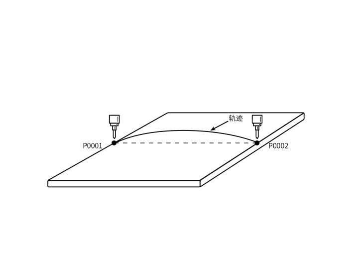
- NOP
- MOVJ P0001 VJ = 10 % PL =1 ACC = 5 DEC = 5 0
- MOVJ P0002 VJ = 10 % PL =1 ACC = 5 DEC = 5 0
- END
Example description: Robot moves from P0001 to P0002 via joint interpolation.
MOVL - Linear
Format: MOVL [Instruction Name] P/GP [Variable] V [Speed] PL [Smoothing] ACC [Acceleration Ratio] DEC [Deceleration Ratio] TIME [Early Execution Time, displays 0 if not set].
Function: During robot movement to target point, the end-effector trajectory is a straight line.
Parameters:
| Point | Use local position variable (P) or global position variable (GP). When value is "New", inserting this instruction creates a new P variable and records robot's current position to the P variable |
|---|---|
| V | Linear interpolation speed, range 1-1000 (default Cartesian parameter max speed is 1000, range varies based on actual Cartesian parameters), unit is mm/s |
| PL | Smoothing level, range [0,5] |
| ACC | Acceleration ratio, range [1,100] |
| DEC | Deceleration ratio, range [1,100] |
| TIME | Early execution time, unit ms |
| DISTANCE | Early distance, unit mm |
| PROPORTION | Early progress, unit % |
Example:
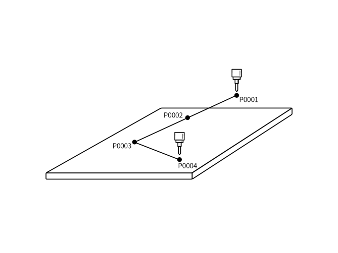
- NOP
- MOVL P0001 V = 200 mm/s PL = 0 ACC = 20 DEC=20 0
- MOVL P0002 V = 200 mm/s PL = 0 ACC = 20 DEC=20 0
- MOVL P0003 V = 200 mm/s PL = 0 ACC = 20 DEC=20 0
- MOVL P0004 V = 200 mm/s PL = 0 ACC = 20 DEC=20 0
- END
Example description: Robot moves from P0001 to target point via linear interpolation. During motion, the end-effector trajectory is a straight line.
MOVC - Circular Arc
Format: MOVC [Instruction Name] P/GP [Variable] V [Speed] PL [Smoothing] ACC [Acceleration Ratio] DEC [Deceleration Ratio] TIME [Early Execution Time, displays 0 if not set].
Function: Move to three taught points via circular arc interpolation
Parameters:
| Point | Use local position variable (P) or global position variable (GP). When value is "New", inserting this instruction creates a new P variable and records robot's current position to the P variable |
|---|---|
| V | Linear interpolation speed, range 1-1000 (default Cartesian parameter max speed is 1000, range varies based on actual Cartesian parameters), unit is mm/s |
| PL | Smoothing level, range [0,5] |
| ACC | Acceleration ratio, range [1,100] |
| DEC | Deceleration ratio, range [1,100] |
| TIME | Early execution time, unit ms |
| DISTANCE | Early distance, unit mm |
| PROPORTION | Early progress, unit % |
| SPIN | Taught orientation: Orientation runs directly from first point to third point. Constant inclination: Maintain first point's inclination throughout the entire trajectory (second and third point orientations don't affect) Variable: 0 = taught orientation, 1 = constant inclination |
Notes: To complete a full circular arc trajectory, insert one MOVJ or MOVL instruction, then two MOVC instructions. Otherwise program will report error (Robot 1 instruction error, isolated MOVC instruction). To continue another arc from the end of a previous arc, no MOVJ or MOVL instruction is needed.
Example:
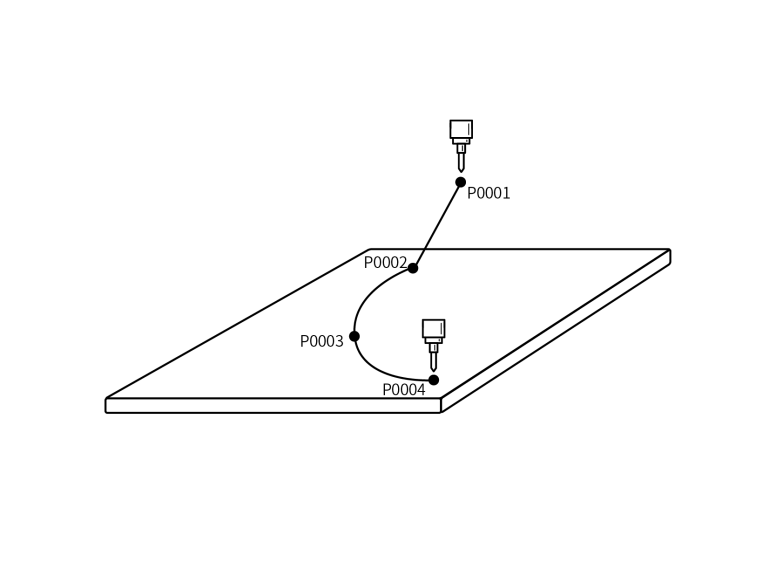
- NOP
- MOVL P0001 V=100mm/s PL=0 ACC=1 DEC=1 0
- MOVL P0002 V=100mm/s PL=0 ACC=1 DEC=1 0 Arc start point
- MOVC P0003 V=100mm/s PL=0 ACC=10 DEC=10 0 Arc mid point
- MOVC P0004 V=100mm/s PL=0 ACC=10 DEC=10 0 Arc end point
- END
Example description: Robot runs from P0001 to arc start point. After reaching arc start point, begins arc trajectory.
MOVCA - Full Circle
Format: MOVCA [Instruction Name] P/GP [Variable] V [Speed] PL [Smoothing] ACC [Acceleration Ratio] DEC [Deceleration Ratio] TIME [Early Execution Time, displays 0 if not set].
Function: Robot completes full circle trajectory through three taught points.
Parameters:
| Point | Use local position variable (P) or global position variable (GP). When value is "New", inserting this instruction creates a new P variable and records robot's current position to the P variable |
|---|---|
| V | Linear interpolation speed, range 1-1000 (default Cartesian parameter max speed is 1000, range varies based on actual Cartesian parameters), unit is mm/s |
| PL | Smoothing level, range [0,5] |
| ACC | Acceleration ratio, range [1,100] |
| DEC | Deceleration ratio, range [1,100] |
| TIME | Early execution time, unit ms |
| DISTANCE | Early distance, unit mm |
| PROPORTION | Early progress, unit % |
| SPIN | Constant orientation: Full circle orientation is the same as the first taught point's orientation (MOVJ, MOVL calibration orientation), and completes the circle with this orientation 6-axis fixed: Full circle follows each taught point's orientation, while 6-axis remains fixed 6-axis rotating: Full circle follows each taught point's orientation |
Notes: To complete a full circle trajectory, insert one MOVJ or MOVL instruction, then two MOVCA instructions. Otherwise program will report error (Robot 1 instruction error, isolated MOVCA instruction).
Example:
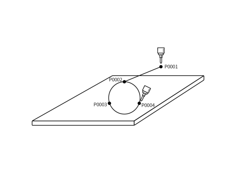
- NOP
- MOVL P0001 V=50mm/s PL=0 ACC=1 DEC=1 0
- MOVL P0002 V=50mm/s PL=0 ACC=1 DEC=1 0 Full circle start point
- MOVC P0003 V=100mm/s PL=0 ACC=10 DEC=10 0 Full circle transition point
- MOVC P0004 V=100mm/s PL=0 ACC=10 DEC=10 0 Full circle end point
- END
Example description: Robot runs from safety point P0001 to full circle start point P0002. After reaching full circle start point, begins full circle trajectory.
MOVS - Curve
Format: MOVS [Instruction Name] P/GP [Variable] V [Speed] PL [Smoothing] ACC [Acceleration Ratio] DEC [Deceleration Ratio] TIME [Early Execution Time, displays 0 if not set].
Function: During welding, cutting, fusion, primer application and other operations, use free curve interpolation. Teaching operations for irregular curve workpieces become easier.
Parameters:
| Point | Use local position variable (P) or global position variable (GP). When value is "New", inserting this instruction creates a new P variable and records robot's current position to the P variable |
|---|---|
| V | Linear interpolation speed, range 1-1000 (default Cartesian parameter max speed is 1000, range varies based on actual Cartesian parameters), unit is mm/s |
| PL | Smoothing level, range [0,5] |
| ACC | Acceleration ratio, range [1,100] |
| DEC | Deceleration ratio, range [1,100] |
| TIME | Early execution time, unit ms |
Notes: Curve trajectory requires at least four taught curve points, otherwise program will report error (Robot 1 instruction error, MOVS instruction cannot be less than 4).
Example: Use curve interpolation to teach four points, forming a curve trajectory.
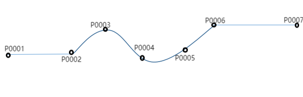
- NOP
- MOVL P0001 V = 100mm/s PL = 0 ACC = 10 DEC = 10 0 Safety point
- MOVS P0002 V = 100 mm/s PL = 0 ACC = 10 DEC = 10 0 Curve start point
- MOVS P0003 V = 100mm/s PL = 0 ACC = 10 DEC = 10 0 Curve mid point
- MOVS P0004 V = 100 mm/s PL = 0 ACC = 10 DEC = 10 0 Curve mid point
- MOVS P0005 V = 100 mm/s PL = 0 ACC = 10 DEC = 10 0 Curve mid point
- MOVS P0006 V = 100mm/s PL = 0 ACC = 10 DEC = 10 0 Curve end point
- MOVL P0007 V = 100mm/s PL = 0 ACC = 10 DEC = 10 0 Trajectory end point
- END
Example description: Robot runs from P0001 to curve trajectory start point. After reaching curve start point, begins curve trajectory P0002-P0006. After completing entire curve trajectory, finally runs to P0007. Entire motion trajectory is complete.
IMOV - Incremental
Format: IMOV [Instruction Name] RP [Variable] V/VJ [Speed] RF BF TF UF [Coordinate System] PL [Smoothing] ACC [Acceleration Ratio] DEC [Deceleration Ratio] TIME [Early Execution Time, displays 0 if not set].
Function: Move from current position by set increment value via joint or linear interpolation.
Parameters:
| Parameter | Description |
|---|---|
| RP | Increment variable, records increment position data |
| V/VJ | V: Linear interpolation speed; VJ: Joint interpolation speed |
| PL | Smoothing level, range [0,5] |
| Coordinate System | Joint, Cartesian, Tool, User coordinates |
| ACC | Acceleration ratio, range [1,100] |
| DEC | Deceleration ratio, range [1,100] |
| TIME | Early execution time, unit ms |
| DISTANCE | Early distance, unit mm, supports non-joint interpolation |
| PROPORTION | Early progress, unit %, supports non-joint interpolation |
Notes: When inserting incremental instruction, if coordinate system is tool coordinates, the point tool must match the actual tool used, otherwise program will report error (e.g., Robot 1 tool usage error, point tool is 1, actual tool is 2).
Example:
Coordinate system can select joint, Cartesian, tool, user four coordinate systems. Corresponding axis with positive value is positive direction, negative value is negative direction, 0 means no movement.
| Coordinate System | Set Position Parameter Values | Example Description |
|---|---|---|
| Joint (RF) | J1-(10) J2-(-5) J3-0 J4-0 J5-0 J6-0 | IMOV RP0001 VJ=10% RF PL=0 ACC=1 DEC=1 0Robot increases J1 axis by 10 and decreases J2 axis by 5 in current joint coordinate position, other axes unchanged |
| Cartesian (BF) | X-(-20) Y-(35) Z-(50) A-0 B-0 C-0 | IMOV RP0002 V=10mm/s BF PL=0 ACC=1 DEC=1 0Robot decreases X axis by 20mm, increases Y axis by 35mm, increases Z axis by 50mm in current Cartesian position, other axes unchanged |
| Tool (TF) | TX-(10) TY-(20) TZ-(-30) TA-(1) TB-0 TC-0 | IMOV RP0003 V=10mm/s TF PL=0 ACC=1 DEC=1 0Robot increases tool X axis by 10mm, increases Y axis by 20mm, decreases Z axis by 30mm, increases orientation axis A by 1rad in current tool position, other axes unchanged |
| User (UF) | UX-(0) UY-(-20) UZ-(30) UA-(0) UB-(-1) UC-0 | IMOV RP0004 V=10mm/s UF PL=0 ACC=1 DEC=1 0Robot decreases user Y axis by 20mm, increases Z axis by 30mm, decreases orientation axis B by 1rad in current user position, other axes unchanged |
External Axis Instructions
Question: What is an external axis?
Answer: External axis refers to axes added beyond the robot body for work requirements, used in spraying, welding, cutting and other industries.
Question: How to set up external axis?
Answer: Click Settings - External Axis Parameters - External Axis Type, click [Modify] to set external axis group count, external axis model, click Save, then click [Axis Group Combination] and select external axis group in the axis group combination configuration interface.
Question: How to set external axis parameters?
Answer: Click Settings - External Axis Parameters to enter external axis joint interface. Calibrate external axis (refer to "External Axis User Manual" for calibration method), set external axis joint parameters, etc. After parameter setting is complete, external axis can be used.
Notes: When modifying external axis instruction speed, acceleration ratio and deceleration ratio will automatically display in 1:1 relationship with speed. To modify acceleration or deceleration ratio, manual operation is required.
MOVJEXT - External Axis Point-to-Point
Format: MOVJEXT [Instruction Name] E/GE [Variable] VJ [Speed] PL [Smoothing] ACC [Acceleration Ratio] DEC [Deceleration Ratio] TIME [Early Execution Time, displays 0 if not set].
Function: Robot moves to taught position via joint interpolation. External axis rotates while robot moves on external axis through taught points.
Parameters:
| Parameter | Description |
|---|---|
| E | Variable recording robot and external axis position data. When value is "New", inserting this instruction creates a new E variable and records robot and external axis current position to the E variable |
| VJ | Joint interpolation speed, range [1,100] |
| EVJ | External axis speed, range [1,100] |
| PL | Smoothing level, range [0,5] |
| ACC | Acceleration ratio, range [1,100] |
| DEC | Deceleration ratio, range [1,100] |
| TIME | Early execution time for next instruction, unit ms |
Example:
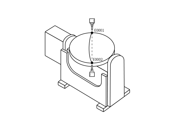
- NOP
- MOVJEXT E0001 VJ = 10 % PL = 0 ACC= 10 DEC = 10 0
- MOVJEXT E0002 VJ = 20 % PL = 0 ACC= 10 DEC = 10 0
- END
Example description: Robot moves from E0001 to E0002, and external axis rotates during E0001-E0002 movement.
MOVLEXT - External Axis Linear
Format: MOVLEXT [Instruction Name] E/GE [Variable] V [Speed] PL [Smoothing] ACC [Acceleration Ratio] DEC [Deceleration Ratio] SYNC [Positioner sync, "0" means sync off, "1" means sync on] TIME [Early Execution Time, displays 0 if not set].
Function: Robot moves to taught position via linear interpolation. External axis rotates while robot moves linearly on external axis.
Parameters:
| Parameter | Description |
|---|---|
| E | Variable recording robot and external axis position data. When value is "New", inserting this instruction creates a new E variable and records robot and external axis current position to the variable |
| V | Linear interpolation speed, range 1-1000 (default Cartesian parameter max speed is 1000), unit is mm/s |
| EVJ | External axis speed, range [1,100] |
| PL | Smoothing level, range [0,5] |
| ACC | Acceleration ratio, range [1,100] |
| DEC | Deceleration ratio, range [1,100] |
| TIME | Early execution time for next instruction, unit ms |
| SYNC | Positioner sync Sync on: Robot and external axis move linearly together Sync off: Robot moves linearly in space, external axis moves independently to target position |
Notes: Before using external axis linear instruction, select external axis group number in external axis calibration interface, otherwise program will report error during execution. External axis must be accurately calibrated, otherwise synchronization between robot and external axis will have issues during external axis linear instruction.
Example:
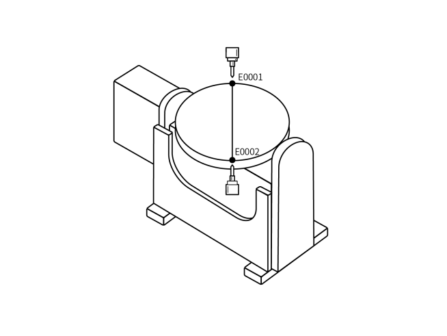
- NOP
- MOVLEXT E0001 V = 50 mm/s PL = 0 ACC = 1 DEC = 1 SYNC = 1 0
- MOVLEXT E0002 V = 50 mm/s PL = 0 ACC = 1 DEC = 1 SYNC = 1 0
- END
Example description: Robot moves from safety point to E0001. After reaching E0001, robot and external axis collaborate to move linearly to E0002.
MOVCEXT - External Axis Circular Arc
Format: MOVCEXT [Instruction Name] E/GE [Variable] V [Speed] PL [Smoothing] ACC [Acceleration Ratio] DEC [Deceleration Ratio] SYNC [Positioner sync, "0" means sync off, "1" means sync on] TIME [Early Execution Time, displays 0 if not set].
Function: Robot moves to taught position via circular arc interpolation. External axis moves via joint interpolation. Robot end-effector moves from E0001-E0003 on circular arc trajectory, and external axis rotates during arc movement.
Parameters:
| Parameter | Description |
|---|---|
| E | Variable recording robot and external axis position data. When value is "New", inserting this instruction creates a new E variable and records robot and external axis current position to the variable |
| V | Linear interpolation speed, range 1-1000 (default Cartesian parameter max speed is 1000, range varies based on actual Cartesian parameters), unit is mm/s |
| EVJ | External axis speed, range [1,100] |
| PL | Smoothing level, range [0,5] |
| ACC | Acceleration ratio, range [1,100] |
| DEC | Deceleration ratio, range [1,100] |
| TIME | Early execution time for next instruction, unit ms |
| SYNC | Positioner sync Sync on: Robot and external axis move on circular arc together Sync off: Robot moves on circular arc in space, external axis moves independently to target position |
Notes: Before using external axis circular arc instruction, select external axis group number in external axis calibration interface, otherwise program will report error during execution. External axis must be accurately calibrated, otherwise synchronization between robot and external axis will have issues during external axis circular arc instruction.
Example:
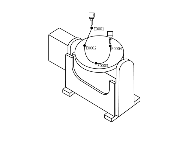
- NOP
- MOVL E0001 V = 100 mm/s PL = 0 ACC = 1 DEC = 1 0 Safety point
- MOVLEXT E0002 V = 50 mm/s PL = 0 ACC = 1 DEC = 1 SYNC = 1 0 Arc start point
- MOVCEXT E0003 V = 50 mm/s PL = 0 ACC = 1 DEC = 1 SYNC = 1 0 Arc mid point
- MOVCEXT E0004 V = 50 mm/s PL = 0 ACC = 1 DEC = 1 SYNC = 1 0 Arc end point
- END
Example description: Robot runs from current position to E0001. From E0001, runs to arc start point E0002. After reaching E0002, runs to arc mid point E0003. At E0003, completes entire external axis arc trajectory. During E0002-E0004 movement, robot and external axis collaborate on circular arc. Robot moves to taught target point while external axis rotates synchronously.
MOVSEXT - External Axis Curve
Format: MOVSEXT [Instruction Name] E/GE [Variable] V [Speed] PL [Smoothing] ACC [Acceleration Ratio] DEC [Deceleration Ratio] SYNC [Positioner sync, "0" means sync off, "1" means sync on] TIME [Early Execution Time, displays 0 if not set].
Function: Robot moves to taught position via curve interpolation. External axis moves via curve interpolation. Robot end-effector moves from E0002-E0005 on curve trajectory, and external axis rotates during curve movement.
Parameters:
| Parameter | Description |
|---|---|
| E | Variable recording robot and external axis position data. When value is "New", inserting this instruction creates a new E variable and records robot and external axis current position to the variable |
| V | Linear interpolation speed, range 1-1000 (default Cartesian parameter max speed is 1000, range varies based on actual Cartesian parameters), unit is mm/s |
| EVJ | External axis speed, range [1,100] |
| PL | Smoothing level, range [0,5] |
| ACC | Acceleration ratio, range [1,100] |
| DEC | Deceleration ratio, range [1,100] |
| TIME | Early execution time for next instruction, unit ms |
| SYNC | Positioner sync Sync on: Robot and external axis move on curve together Sync off: Robot moves on curve in space, external axis moves independently to target position |
Notes: Before using external axis curve instruction, select external axis group number in external axis calibration interface, otherwise program will report error during execution. External axis must be accurately calibrated, otherwise synchronization between robot and external axis will have issues during external axis curve instruction.
Example:
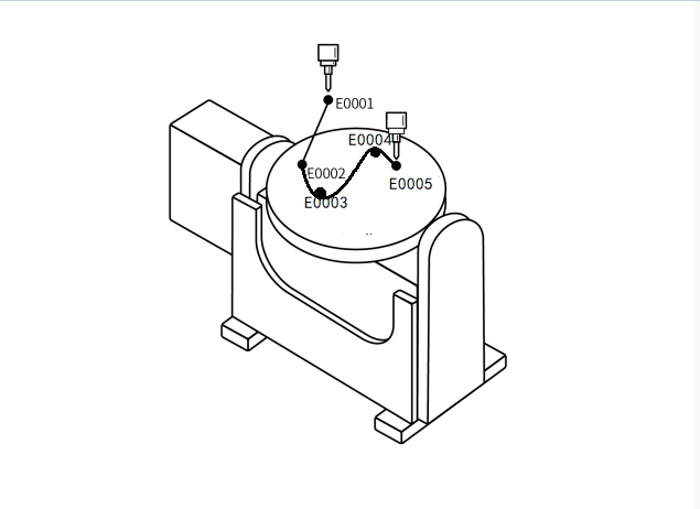
- NOP
- MOVL E0001 V = 100 mm/s PL = 0 ACC = 1 DEC = 1 0 Safety point
- MOVSEXT E0002 V = 50 mm/s PL = 0 ACC = 1 DEC = 1 SYNC = 1 0 Curve start point
- MOVSEXT E0003 V = 50 mm/s PL = 0 ACC = 1 DEC = 1 SYNC = 1 0 Curve transition point
- MOVSEXT E0004 V = 50 mm/s PL = 0 ACC = 1 DEC = 1 SYNC = 1 0 Curve transition point
- MOVSEXT E0005 V = 50 mm/s PL = 0 ACC = 1 DEC = 1 SYNC = 1 0 Curve end point
- END
Example description: Robot runs from current position to E0001. From E0001, runs to curve start point E0002. After reaching E0002, runs to curve transition point E0003. At E0005, completes entire external axis curve trajectory. During E0002-E0005 movement, robot and external axis collaborate on curve. Robot moves to taught target point while external axis rotates synchronously.
SPEED - Global Speed
Format: SPEED [Instruction Name] 10% [Set speed parameter].
Function: Globally modify the speed of motion instructions below the SPEED instruction.
Parameters:
| Parameter | Description |
|---|---|
| SPEED range [1,200]% | Manual: Directly enter speed parameter Variable: Set speed parameter through variable assignment |
Notes: Speed calculation for motion instructions below SPEED instruction:
Linear speed: Instruction speed * Status bar speed * SPEED global speed percentage.
Axis speed: Joint rated forward speed * Instruction speed * Status bar speed * SPEED global speed percentage.
During program execution, current speed and maximum speed can be viewed in Monitor - Axis Speed interface.
Example: Set global speed to 50%:
- NOP
- MOVL GP0001 V = 200 mm/s PL = 2 ACC = 20 DEC=20 0
- MOVL GP0002 V = 200 mm/s PL = 2 ACC = 20 DEC=20 0
- SPEED= 80%
- MOVL GP0003 V = 100 mm/s PL = 2 ACC = 20 DEC=20 0
- MOVL GP0004 V = 100 mm/s PL = 2 ACC = 20 DEC=20 0
- MOVL GP0005 V = 100 mm/s PL = 2 ACC = 20 DEC=20 0
- END
Example description: GP0001-GP0002 linear speed: Instruction speed 200 mm/s * Global speed 50%.
GP0002-GP0004 linear speed: Instruction speed 100mm/s * Global speed 50% * SPEED global speed 80%.
SAMOV - Fixed Point Move
Format: SAMOV [Instruction Name] AP [Variable] V/VJ [Speed] RF BF TF UF [Coordinate System] PL [Smoothing] ACC [Acceleration Ratio] DEC [Deceleration Ratio] TIME [Early Execution Time, displays 0 if not set].
Function: Robot moves to set point position.
Parameters:
| Parameter | Description |
|---|---|
| AP | Fixed point move variable, records position data |
| V/VJ | V: Linear interpolation speed VJ: Joint interpolation speed |
| PL | Smoothing level, range [0,5] |
| Coordinate System | Joint, Cartesian, Tool, User coordinates |
| ACC | Acceleration ratio, range [1,100] |
| DEC | Deceleration ratio, range [1,100] |
| TIME | Early execution time, unit ms |
| DISTANCE | Early distance, unit mm, supports non-joint interpolation |
| PROPORTION | Early progress, unit %, supports non-joint interpolation |
Parameter Settings:
| Coordinate System | Set Position Parameter Values | Example Description |
|---|---|---|
| Joint (RF) | J1-(10) J2-(-5) J3 J4 J5 J6 | SAMOV AP0001 VJ=10% RF PL=0 ACC=1 DEC=1 0Robot moves to set joint position. Under joint coordinates, J1 axis coordinate is 10, J2 axis coordinate is -5, other axes unchanged |
| Cartesian (BF) | X-(300) Y-(0) Z-(120) A B C | SAMOV AP0002 V=10mm/s BF PL=0 ACC=1 DEC=1 0Robot moves to set Cartesian position. Under Cartesian coordinates, X axis coordinate is 300, Y axis coordinate is 0, Z axis coordinate is 120, other axes unchanged |
| Tool (TF) | TX-(300) TY-(0) TZ TA-(3.14) TB TC | SAMOV AP0003 V=10mm/s TF PL=0 ACC=1 DEC=1 0Robot moves to tool position. Under tool coordinates, X axis coordinate is 300, Y axis coordinate is 0, orientation axis A coordinate is 3.14rad, other axes unchanged |
| User (UF) | UX UY-(120) UZ-(100) UA UB UC | SAMOV AP0004 V=10mm/s UF PL=0 ACC=1 DEC=1 0Robot moves to user position. Under user coordinates, Y axis coordinate is 120, Z axis coordinate is 100, other axes unchanged |
Notes: If an axis does not need to be moved, leave the axis coordinate blank, do not fill in 0 (if 0 is filled, the corresponding axis position will become 0 when running this instruction).
Example:
Assume robot's current joint coordinate position is (10, 20, 30, 40, 50, 60). Insert fixed point move instruction, select joint coordinate system, set the coordinate axis parameters to modify.
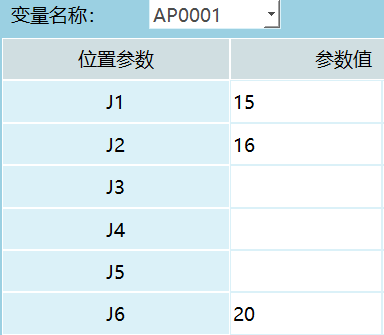
SAMOV AP0004 VJ=10% UF PL=0 ACC=1 DEC=1 0;
Example description: Execute fixed point move instruction, robot moves to target position (15, 16, 30, 40, 50, 20).
Dual-Robot Instructions
Dual-Robot Working Mode: Dual-robot collaboration is completed by two 6-axis serial robots working together. Throughout the entire work process, robots coordinate with each other to achieve the final task goal.
Question: How to set up dual-robot mode?
Answer:
- Click Settings - Robot Parameters - Robot Type, set robot count;
- Both robot types select 6-axis serial robot;
- Click [Save] to restart system;
- Import configuration in Robot 1, robot_A (Robot 1 configuration) and robot_B (Robot 2 configuration);
- In Settings - System Settings - Maintenance Mode, enable [Enable Dual-Robot Synchronization Mode].
Question: How to teach positions after inserting dual-robot instructions?
Answer: Note: Dual-robot point-to-point, dual-robot linear, dual-robot circular arc and dual-robot full circle instructions only support insertion in Robot 1.
- Insert dual-robot instruction in Robot 1 instruction interface;
- Jog Robot 1 to target position;
- Switch to Robot 2 and jog to target position.
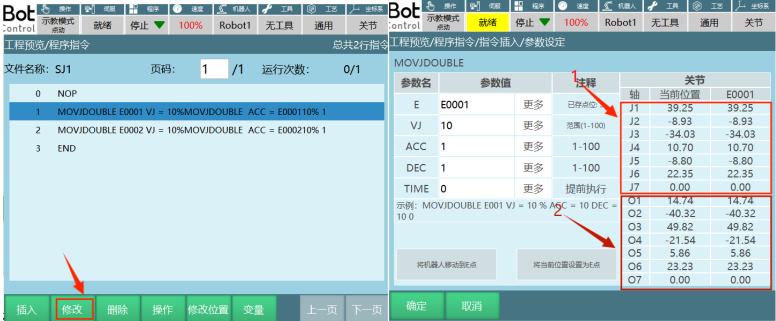
In Robot 1 program instruction interface, select the instruction to modify and click [Modify]. In the parameter setting interface, click [Set Current Position as E Point]. Prompt appears "Continue modifying position?". Click [OK] to store current position in target variable. Click [Cancel] to not record robot's current position to target variable, allowing continued movement to desired position. Part 1 in the figure shows Robot 1's current position and stored variable position. Part 2 shows Robot 2's current position and stored variable position.
Question: How to run program in dual-robot mode?
Answer:
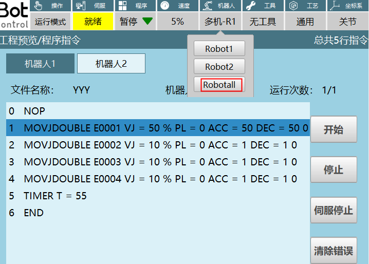
- Switch to run mode, click robot select "Robotall" to enter dual-robot run mode interface;
- Start both robots simultaneously by pressing [Start] on teach pendant. Pause both robots by pressing [Stop];
- To start Robot 1 individually, click [Robot 1] then click [Start] as shown. Robot 1 starts working. Click [Stop] to pause Robot 1. Robot 2 start/stop operations are the same as Robot 1.
Notes: When connecting dual-robot and multi-robot, direct connection is required. Do not connect through switches due to cable length issues, as this may cause robot runaway!
MOVJDOUBLE - Dual-Robot Point-to-Point
Format: MOVJDOUBLE [Instruction Name] E/GE [Variable] VJ [Speed] ACC [Acceleration Ratio] DEC [Deceleration Ratio] TIME [Early Execution Time, displays 0 if not set].
Function: Two robots move from one point to another via joint interpolation.
Parameters:
| Parameter | Description |
|---|---|
| E/GE | Variable recording robot position data. When value is "New", inserting this instruction creates a new E variable and records robot's current position to the E variable |
| VJ | Joint interpolation speed, range: [1,100] |
| PL | Smoothing level, range [0,5] |
| ACC | Acceleration ratio, range [1,100] |
| DEC | Deceleration ratio, range [1,100] |
| TIME | Early execution time, unit ms |
Example:
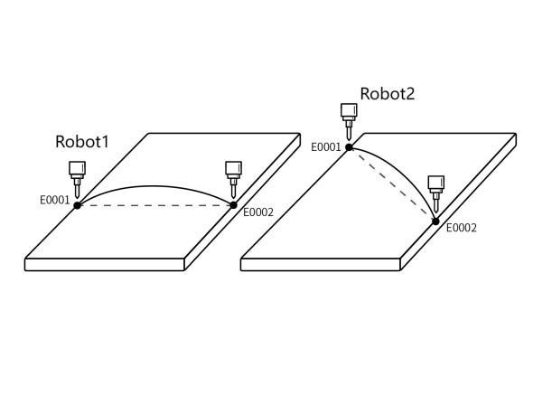
- NOP
- MOVJDOUBLE E0001 VJ = 10 % PL = 0 ACC= 10 DEC = 10 0
- MOVJDOUBLE E0002 VJ = 15 % PL = 0 ACC= 10 DEC = 10 0
- END
Example description: When program starts, both robots move from E0001 to E0002 via joint interpolation based on taught positions.
MOVLDOUBLE - Dual-Robot Linear
Format: MOVLDOUBLE [Instruction Name] E/GE [Variable] V [Speed] ACC [Acceleration Ratio] DEC [Deceleration Ratio] TIME [Early Execution Time, displays 0 if not set].
Function: Control two robots to run to target position via linear interpolation. Robot end-effector trajectory is a straight line.
Parameters:
| Parameter | Description |
|---|---|
| E/GE | Variable recording robot position data. When value is "New", inserting this instruction creates a new E variable and records robot's current position to the E variable |
| V | Linear interpolation speed, range 1-1000 (default Cartesian parameter max speed is 1000, range varies based on actual Cartesian parameters), unit is mm/s |
| PL | Smoothing level, range [0,5] |
| ACC | Acceleration ratio, range [1,100] |
| DEC | Deceleration ratio, range [1,100] |
| TIME | Early execution time, unit ms |
Example:

- NOP
- MOVLDOUBLE E0001 V = 100 mm/s PL = 0 ACC= 10 DEC = 10 0
- MOVLDOUBLE E0002 V = 50 mm/s PL = 0 ACC= 10 DEC = 10 0
- MOVLDOUBLE E0003 V = 50 mm/s PL = 0 ACC= 10 DEC = 10 0
- MOVLDOUBLE E0004 V = 50 mm/s PL = 0 ACC= 10 DEC = 10 0
- END
Example description: When program starts, both robots move from E0001 to E0004 via linear interpolation based on taught positions. Robot end-effector trajectory is a straight line.
MOVCDOUBLE - Dual-Robot Circular Arc
Format: MOVCDOUBLE [Instruction Name] E/GE [Variable] V [Speed] ACC [Acceleration Ratio] DEC [Deceleration Ratio] TIME [Early Execution Time, displays 0 if not set].
Function: Both robots move on circular arc trajectory when program starts.
Parameters:
| Parameter | Description |
|---|---|
| E/GE | Variable recording robot position data. When value is "New", inserting this instruction creates a new E variable and records robot's current position to the E variable |
| V | Linear interpolation speed, range 1-1000 (default Cartesian parameter max speed is 1000, range varies based on actual Cartesian parameters), unit is mm/s |
| PL | Smoothing level, range [0,5] |
| ACC | Acceleration ratio, range [1,100] |
| DEC | Deceleration ratio, range [1,100] |
| TIME | Early execution time, unit ms |
Example:
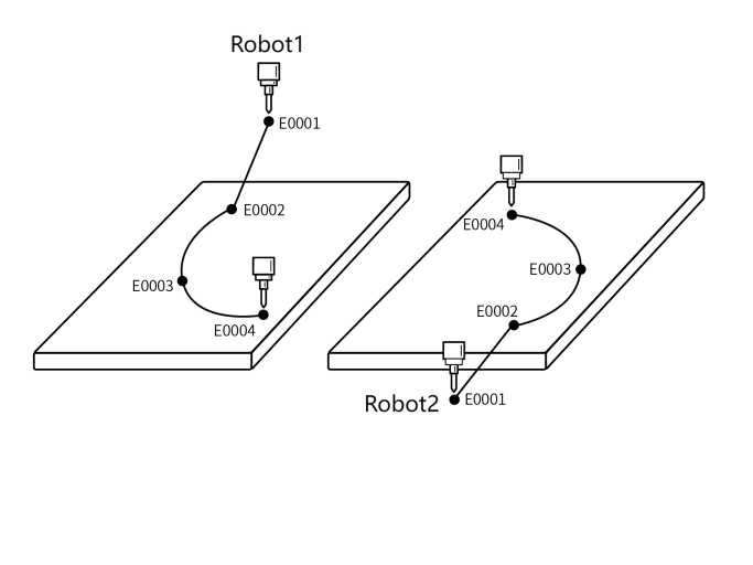
- NOP
- MOVLDOUBLE E0001 V = 10 % PL = 0 ACC= 10 DEC = 10 0
- MOVLDOUBLE E0002 V = 10 % PL = 0 ACC= 10 DEC = 10 0 Arc start point
- MOVCDOUBLE E0003 V = 100 mm/s PL = 0 ACC= 10 DEC = 10 0 Arc transition point
- MOVCDOUBLE E0004 V = 100mm/s PL = 0 ACC= 10 DEC = 10 0 Arc end point
- END
Example description: When program starts, both robots move from E0001 to E0002 via linear interpolation based on taught positions. At E0002, complete entire circular arc trajectory.
MOVCADOUBLE - Dual-Robot Full Circle
Format: MOVCADOUBLE [Instruction Name] E/GE [Variable] V [Speed] ACC [Acceleration Ratio] DEC [Deceleration Ratio] TIME [Early Execution Time, displays 0 if not set].
Function: Both robots simultaneously complete full circle trajectory through dual-robot collaboration.
Parameters:
| Parameter | Description |
|---|---|
| E/GE | Variable recording robot position data. When value is "New", inserting this instruction creates a new E variable and records robot's current position to the E variable |
| V | Linear interpolation speed, range 1-1000 (default Cartesian parameter max speed is 1000, range varies based on actual Cartesian parameters), unit is mm/s |
| PL | Smoothing level, range [0,5] |
| ACC | Acceleration ratio, range [1,100] |
| DEC | Deceleration ratio, range [1,100] |
| TIME | Early execution time, unit ms |
| SPIN: Robot tip rotation | Constant orientation: Full circle orientation is the same as the first taught point's orientation (MOVJ, MOVL calibration orientation), and completes the circle with this orientation 6-axis fixed: Full circle follows each taught point's orientation, while 6-axis remains fixed 6-axis rotating: Full circle follows each taught point's orientation |
Example:
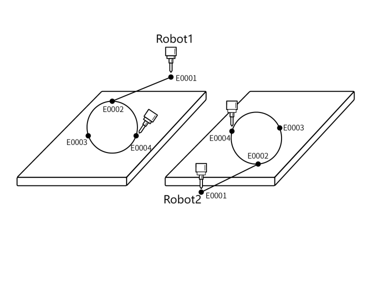
- NOP
- MOVLDOUBLE E0001 V = 10 % PL = 0 ACC= 10 DEC = 10 0
- MOVLDOUBLE E0002 V = 10 % PL = 0 ACC= 10 DEC = 10 0 Full circle start point
- MOVCADOUBLE E0003 V = 25 mm/s PL = 0 ACC= 10 DEC = 10 0 Full circle transition point
- MOVCADOUBLE E0004 V = 25 mm/s PL = 0 ACC= 10 DEC = 10 0 Full circle end point
- END
Example description: When program starts, both robots move from E0001 to E0002 via linear interpolation based on taught positions. At E0002, complete entire full circle trajectory.
MOVCOMM - External Point
Format: MOVCOMM [Instruction Name] MOVJ/MOVL/MOVS/MOVC [Interpolation Method] V/VJ [Speed] PL [Smoothing] ACC [Acceleration Ratio] DEC [Deceleration Ratio] TIME [Early Execution Time, displays 0 if not set].
Function: Move to target position via external point instruction using specified interpolation method. External point positions can be sent through 6000, 7000 ports and vision process.
Parameters:
| Parameter | Description |
|---|---|
| Interpolation Method | Joint, Linear, Curve, Circular Arc |
| V/VJ | V: Linear interpolation speed range 2-1000 (default Cartesian parameter max speed is 1000), unit is mm/s VJ: Joint interpolation speed |
| PL | Smoothing level, range [0,5] |
| ACC | Acceleration ratio, range [1,100] |
| DEC | Deceleration ratio, range [1,100] |
| TIME | Early execution time, unit ms |
Question: How to run external point in vision process?
- Set parameters in Vision Process - Vision Parameters interface. For single point, enable Single Target button. For continuous trajectory, disable Single Target button;
- In Vision Position Parameters interface, select Trajectory for received position type;
- Insert external point instruction, robot starts moving to sent positions.
Example 1:
- NOP
- VISION_RUN ID =1 Vision start
- VISION_TRG ID =1 Vision trigger
- VISION_TRACE ID =1 Get vision trajectory position
- MOVCOMM MOVJ VJ=10% PL=0 ACC=10 DEC=10 0 External point
- VISION_END ID =1 Vision end
- END
Example description: Camera communication successful, sends positions. Get trajectory position storage location and select external point motion queue. Insert external point instruction below trajectory position instruction. Robot starts moving on external point trajectory sent by camera.
Question: How to run external point instruction through 6000, 7000 ports?
Answer: First note: When connecting to 6000 port, the teach pendant must be removed!
- 7000 port: Look up command word according to 7000 port protocol, send data (note send format, incorrect format will cause sent data to be ineffective).
- Insert external point instruction. Send positions according to "INEXBOT Network Function Protocol" format. After successful send, running external point instruction will cause robot to run to target positions based on sent data.
- Robot will run individual points or continuous trajectory based on sent data.
Example 2: Command word 1E02, select "Continuous Trajectory", "Send all trajectory points at once". Set parameters are for reference only. For other parameter settings, refer to 7000 port protocol.
{ //When selecting "Continuous Trajectory", "Send partial points each time", "Run after receiving complete trajectory", protocol format
"robot":1,
"clearBuffer":1,//Clear motion trajectory buffer queue
"end":0,//When "end" is 1, stop previous continuous transmission, below data can be omitted; if 0, "end" can be omitted
"targetMode":1, //0: Individual points, 1: Continuous trajectory
"sendMode":1, //0: Send all trajectory points at once, 1: Send partial points each time
"runMode":0, //Only for continuous trajectory with partial points each time. 0: Run after receiving complete trajectory, 1: Run while receiving
"sum":10, //Only effective for "Run after receiving complete trajectory", total frames to send
"count":1, //Only effective for "Run after receiving complete trajectory", current frame number
"cfg":{ //Only needs to be set in first frame, only effective in first frame
"coord":"ACS",
"extMove":0, //1 means external axis motion; 0 or omitted means none
"sync":0//0 or omitted means external axis not synced, 1: External axis synced
"speed":100, //If omitted, default value is used
"acc":100, //If omitted, default value is used
"timeout":100 //ms, timeout. If omitted, no timeout detection, range 10-10000
//Only effective for "Run after receiving complete trajectory"
},
"targetVec":[
{
"pos":[ 1.1, 1.2, 1.3, 1.4, 1.5, 1.6, 1.7, 2.1, 2.2, 2.3, 2.4, 2.5 ],
"axisVel":[ 1.1, 1.2, 1.3, 1.4, 1.5, 1.6, 1.7, 2.1, 2.2, 2.3, 2.4, 2.5 ],
"axisAcc":[ 1.1, 1.2, 1.3, 1.4, 1.5, 1.6, 1.7, 2.1, 2.2, 2.3, 2.4, 2.5 ],
"timeStamp":10 //ms, time relative to start point when running to this position
},
]
}
EXTMOV - External Axis Follow
Format: EXTMOV [Instruction Name] O1 [External axis to move] COMST_T [External axis follow type] 10 [Multiplier].
Function: External axis follows robot at linear speed multiplier or constant speed.
Parameters:
| Parameter | Description |
|---|---|
| External Axis | Select O1-O5 axis for follow |
| Type | External axis speed can be viewed in Monitor - Axis Speed Follow (0): Speed changes with robot real-time speed Constant (1): Run at constant speed |
| Speed Value | When follow type is constant, speed value can be manual input or variable |
| K | When follow type is follow, value can be entered K (Multiplier): External axis speed (°/s) = K * Linear speed (mm/s) |
Notes: External axis motion instructions cannot be inserted between external axis follow instructions!
Example 1: External axis follow instruction type constant, constant value 10.
- NOP
- EXTMOV O1 COMST_T 10 Follow start
- MOVL P0001 V=50mm/s PL=0 ACC=1 DEC=1 0
- ENDEXTMOV Follow end
- END
Execution effect: While robot moves to P0001, external axis also moves. During motion, external axis speed remains at 10. After robot reaches P0001, external axis also stops.
Example 2: External axis follow instruction type follow, K=2.
- NOP
- EXTMOV O1 FOLLOW 2 Follow start
- MOVL P0001 V=10mm/s PL=0 ACC=1 DEC=1 0
- ENDEXTMOV Follow end
- END
Example description: While robot moves to P0001, external axis also moves. During motion, external axis speed changes with robot speed. After robot reaches P0001, external axis also stops.
Insert non-motion instruction (e.g., delay instruction):
- If follow type is selected, when executing delay instruction, both external axis and robot stop.
- If constant type is selected, when executing delay instruction, robot stops but external axis continues rotating until delay ends.
GEARIN - Electronic Gear
Format: GEARIN [Instruction Name] J1 [Main axis] O1 [Follow axis] K=2 [Ratio].
Function: External axis follows robot axis motion. Follow axis speed equals selected main axis speed * Ratio K value.
Parameters:
| Parameter | Description |
|---|---|
| Main Axis | Robot's J1-J6 axes |
| External Axis | External axis O1-O5 for follow |
| Ratio K | Follow axis speed (°/s) = K * Main axis speed (°/s) |
Example:
- NOP
- GEARIN J1 O1 2 Electronic gear start
- MOVL P0001 V=10mm/s PL=0 ACC=1 DEC=1 0 Linear instruction
- ENDGEARIN Electronic gear stop
- END
Example description: When robot starts moving, external axis O1 follows. O1 speed = J1 axis speed * 2. When running to electronic gear stop instruction, J1 and O1 axis speeds become 0.
MRESET - Reset External Axis Multi-Turn
Format: MRESET [Instruction Name] 1 [External axis to reset].
Function: After external axis exceeds limits, use this instruction to reset external axis coordinates. Prevents external axis from reporting errors due to limit exceedance.
Parameters:
| Parameter | Description |
|---|---|
| MRESET | All axes: Reset O1-O5 all axes turn count Single axis: Reset selected O1-O5 single axis turn count |
Example:
- NOP
- MOVL P0001 V=10mm/s PL=0 ACC=1 DEC=1 0 Program point 1
- EXTMOV O1 FOLLOW 1 Follow start
- MOVL P0002 V=10mm/s PL=0 ACC=1 DEC=1 0 Program point 2
- ENDEXTMOV Follow end
- MRESET 1 Reset external axis O1
- END
Example description: When inserting external axis follow instruction, external axis follows robot during motion. In this case, external axis can easily exceed set maximum forward/reverse limits. Inserting reset external axis multi-turn instruction changes external axis position to within one turn, preventing limit exceedance errors.
For example: After executing external axis follow instruction, external axis O1 position is 1200°, exceeding set maximum forward/reverse limits. Inserting reset external axis multi-turn instruction resets external axis position to 120°. Calculation: 1200/360, integer part of result is 3 (3 turns), then 1200-360*3=120°.
DRAG_TRAJECTORY - Drag Teaching
Format: DRAG_TRAJECTORY [Instruction Name] Track [Saved drag trajectory] 20% [Trajectory playback speed].
Function: Run recorded drag trajectory through instruction.
Parameters:
| Parameter | Description |
|---|---|
| Trajectory Name | Trajectory name recorded after successful robot recognition |
| Playback Speed | Running speed during trajectory playback |
Example:
- NOP
- DRAG_TRAJECTORY ##Track1$$ 20% Run recorded trajectory 1
- END
Example description: Robot runs recorded trajectory 1 at 20% speed.
SWITCHPAYLOAD - Switch Payload
Format: SWITCHPAYLOAD [Instruction Name] 1 [Payload number].
Function: Used to switch payload parameters.
Parameters:
| Parameter | Description |
|---|---|
| Payload Number | Manual: Directly enter the number to switch Variable: Switch number through variable assignment |
Notes:
- During actual operation, actual payload must match payload parameters.
- Switching payload only switches the currently selected payload number, tool parameters are not affected.
- Affects collision detection and torque feedforward.
Example:
- NOP
- GI001=10
- SWITCHPAYLOAD GI001
- END
Example description: Switch to payload number 10 parameters.
MOVARCH - Arch Motion
Format: MOVARCH [Instruction Name] P/GP [Variable] V [Speed] PL [Smoothing] ACC [Acceleration Ratio] DEC [Deceleration Ratio] Rising Direction [XYZ] Rise Height [Height from target point to highest position] Axis Max Coordinate [Height of highest position] Use Group [Arch parameter table] Vertical Rise Distance [Distance rising from start point] Vertical Fall Distance [Distance falling from target point] Motion Method [Linear interpolation & Joint interpolation] TIME [Early Execution Time, displays 0 if not set] DISTANCE [Early distance, unit mm, supports non-joint interpolation, displays 0 if not set].
Function: Robot moves on arch trajectory.
Arch trajectory diagram:
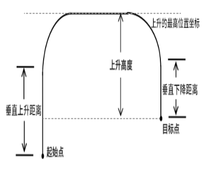
Standard arch trajectory: Height 25mm, width 300mm.
Parameters:
| Parameter | Description |
|---|---|
| Target Point | Use local position variable (P) or global position variable (GP). When value is "New", inserting this instruction creates a new P variable and records robot's current position to the P variable |
| V | Linear interpolation speed, range 1-1000 (default Cartesian parameter max speed is 1000, range varies based on actual Cartesian parameters), unit is mm/s |
| PL | Smoothing level, range [0,5] |
| ACC | Acceleration ratio, range [1,100] |
| DEC | Deceleration ratio, range [1,100] |
| Rising Direction | XYZ direction |
| Rise Height | Height from target point to highest position, unit mm |
| Axis Max Coordinate | Height of highest position |
| Use Group | Call Arch parameter table, supports 7 groups |
| Vertical Rise Distance | Distance rising vertically from start point, unit mm |
| Vertical Fall Distance | Distance falling vertically from target point, unit mm |
| TIME | Early execution time, unit ms |
| DISTANCE | Early distance, unit mm, supports non-joint interpolation |
| PROPORTION | Early progress, unit %, supports non-joint interpolation |
Example:
- NOP
- MOVARCH P0001 V=10 PL=0 ACC=10 DEC=10 Z AXIS_COORDLINE_OR_COORD_MAX=500 STRAIGHT_UP=30 STRAIGHT_DOWN=30 ARCH_TABLE_ENABLE=1 ARCH_TABLE_INDEX=1 DISTANCE=9999 0
- MOVARCH P0001 V=10 PL=0 ACC=10 DEC=10 Z AXIS_COORDLINE_OR_COORD_MAX=500 STRAIGHT_UP=30 STRAIGHT_DOWN=30 ARCH_TABLE_ENABLE=1 ARCH_TABLE_INDEX=1 DISTANCE=9999 0
- END
MOVARCHEXT - Extended Arch
Format: MOVARCHEXT [Instruction Name] P/GP [Variable] P/GP [Variable] P/GP [Variable] V [Speed] PL [Smoothing] ACC [Acceleration Ratio] DEC [Deceleration Ratio] Use Group [Arch parameter table] Vertical Rise Distance [Distance rising from start point] Vertical Fall Distance [Distance falling from target point] Motion Method [Linear interpolation & Joint interpolation] TIME [Early Execution Time, displays 0 if not set] DISTANCE [Early distance, unit mm, supports non-joint interpolation, displays 0 if not set].
Function: Robot moves on extended arch trajectory
Extended arch trajectory diagram
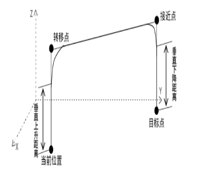
Parameters:
| Parameter | Description |
|---|---|
| Target Point | Use local position variable (P) or global position variable (GP). When value is "New", inserting this instruction creates a new P variable and records robot's current position to the P variable |
| Approach Point | Use local position variable (P) or global position variable (GP). When value is "New", inserting this instruction creates a new P variable and records robot's current position to the P variable |
| Transfer Point | Use local position variable (P) or global position variable (GP). When value is "New", inserting this instruction creates a new P variable and records robot's current position to the P variable |
| V | Linear interpolation speed, range 1-1000 (default Cartesian parameter max speed is 1000), unit is mm/s |
| PL | Smoothing level, range [0,5] |
| ACC | Acceleration ratio, range [1,100] |
| DEC | Deceleration ratio, range [1,100] |
| Use Group | Call Arch parameter table, supports 7 groups |
| Vertical Rise Distance | Distance rising vertically from start point, unit mm |
| Vertical Fall Distance | Distance falling vertically from target point, unit mm |
| TIME | Early execution time, unit ms |
| DISTANCE | Early distance, unit mm, supports non-joint interpolation |
| PROPORTION | Early progress, unit %, supports non-joint interpolation |
Example:
- NOP
- MOVARCHEXT P0001 P0002 P0003 V=10 PL=0 ACC=10 DEC=10 Z AXIS_COORDLINE_OR_COORD_MAX=500 STRAIGHT_UP=30 STRAIGHT_DOWN=30 ARCH_TABLE_ENABLE=1 ARCH_TABLE_INDEX=1 DISTANCE=9999 0
- MOVARCHEXT P0001 P0002 P0003 V=10 PL=0 ACC=10 DEC=10 Z AXIS_COORDLINE_OR_COORD_MAX=500 STRAIGHT_UP=30 STRAIGHT_DOWN=30 ARCH_TABLE_ENABLE=1 ARCH_TABLE_INDEX=1 DISTANCE=9999 0
- END
EIMOVL - External Reference Point Linear
External TCP (Tool Center Point) usage scenario: Robot arm holds workpiece to fixed TCP (e.g., grinding machine) for grinding operations.
External TCP usage method:
- Find a point on the workpiece, then align the found point with TCP tip;
- After alignment, calibrate user coordinate system. User coordinate origin, X, Y three point positions must have the same orientation. After calibration, select this user coordinate system.
Format: EIMOVL [Instruction Name] P/GP [Variable] V [Speed] PL [Smoothing] ACC [Acceleration Ratio] DEC [Deceleration Ratio] TIME [Early Execution Time, displays 0 if not set].
Function: Robot arm holds workpiece to fixed TCP for linear trajectory operations.
Parameters:
| Parameter | Description |
|---|---|
| Point | Use local position variable (P) or global position variable (GP). When value is "New", inserting this instruction creates a new P variable and records robot's current position to the P variable |
| V | Linear interpolation speed, range 1-1000 (default Cartesian parameter max speed is 1000, range varies based on actual Cartesian parameters), unit is mm/s |
| PL | Smoothing level, range [0,5] |
| ACC | Acceleration ratio, range [1,100] |
| DEC | Deceleration ratio, range [1,100] |
| TIME | Early execution time, unit ms |
Example: Each taught external linear point needs to be aligned with TCP.
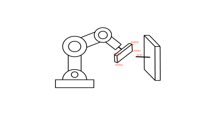
- NOP
- EIMOVL P0001 V=10mm/s PL=0 ACC=10 DEC=10 0
- EIMOVL P0002 V=10mm/s PL=0 ACC=10 DEC=10 0
- EIMOVL P0003 V=10mm/s PL=0 ACC=10 DEC=10 0
- EIMOVL P0004 V=10mm/s PL=0 ACC=10 DEC=10 0
- END
Example description: Robot arm holds workpiece and moves on linear trajectory at fixed TCP based on taught points.
EIMOVC - External Reference Point Circular Arc
Format: EIMOVC [Instruction Name] P/GP [Variable] V [Speed] PL [Smoothing] ACC [Acceleration Ratio] DEC [Deceleration Ratio] TIME [Early Execution Time, displays 0 if not set].
Function: Robot arm holds workpiece to fixed TCP for circular arc trajectory operations.
Parameters:
| Parameter | Description |
|---|---|
| Point | Use local position variable (P) or global position variable (GP). When value is "New", inserting this instruction creates a new P variable and records robot's current position to the P variable |
| V | Linear interpolation speed, range 1-1000 (default Cartesian parameter max speed is 1000, range varies based on actual Cartesian parameters), unit is mm/s |
| PL | Smoothing level, range [0,5] |
| ACC | Acceleration ratio, range [1,100] |
| DEC | Deceleration ratio, range [1,100] |
| TIME | Early execution time, unit ms |
Example: Each taught external arc point needs to be aligned with TCP.
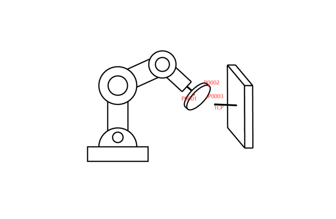
- NOP
- EIMOVC P0001 V=50mm/s PL=0 ACC=10 DEC=10 0
- EIMOVC P0002 V=50mm/s PL=0 ACC=10 DEC=10 0
- EIMOVC P0003 V=50mm/s PL=0 ACC=10 DEC=10 0
- END
Example description: Robot arm holds workpiece and moves on circular arc trajectory at fixed TCP based on taught points.
EIMOVCA - External Reference Point Full Circle
Format: EIMOVCA [Instruction Name] P/GP [Variable] V [Speed] PL [Smoothing] ACC [Acceleration Ratio] DEC [Deceleration Ratio] TIME [Early Execution Time, displays 0 if not set].
Function: Robot arm holds workpiece to fixed TCP for full circle trajectory operations.
Parameters:
| Parameter | Description |
|---|---|
| Point | Use local position variable (P) or global position variable (GP). When value is "New", inserting this instruction creates a new P variable and records robot's current position to the P variable |
| V | Linear interpolation speed, range 1-1000 (default Cartesian parameter max speed is 1000, range varies based on actual Cartesian parameters), unit is mm/s |
| PL | Smoothing level, range [0,5] |
| ACC | Acceleration ratio, range [1,100] |
| DEC | Deceleration ratio, range [1,100] |
| TIME | Early execution time, unit ms |
| SPIN: Robot tip rotation | Constant orientation: Full circle orientation is the same as the first taught point's orientation (MOVJ, MOVL calibration orientation), and completes the circle with this orientation |
Example: Each taught external arc point needs to be aligned with TCP.
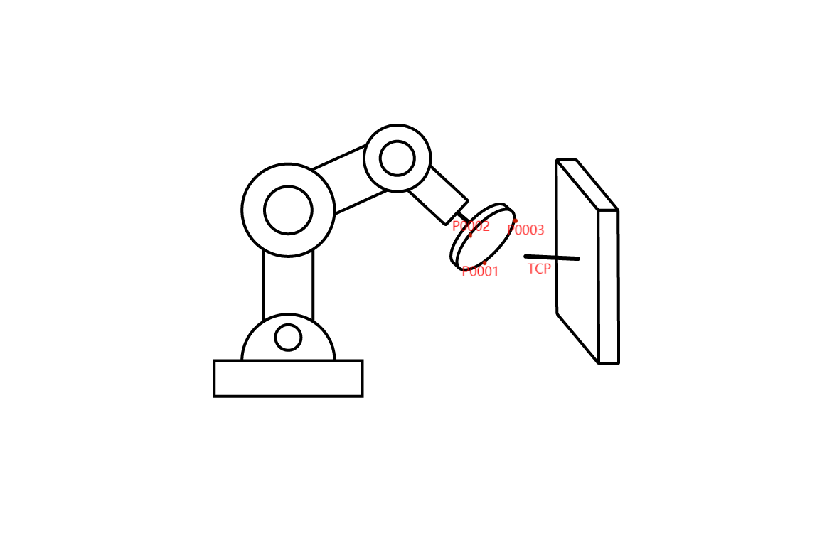
- NOP
- EIMOVL P0001 V=50mm/s PL=0 ACC=10 DEC=10 0
- EIMOVCA P0002 V=10mm/s PL=0 ACC=10 DEC=10 0
- EIMOVCA P0003 V=10mm/s PL=0 ACC=10 DEC=10 0
- END
Example description: Robot arm holds workpiece and moves on full circle trajectory at fixed TCP based on taught points.
Q&A for Retrieval
Q: What is the MOVJ instruction?
A: MOVJ is a point-to-point motion instruction. Robot moves to taught position via joint interpolation, using the shortest path.
Q: What is the MOVL instruction?
A: MOVL is a linear motion instruction. Robot end-effector moves from current position to target point on a straight line trajectory.
Q: What is the MOVC instruction?
A: MOVC is a circular arc motion instruction. Robot defines arc trajectory through start point, mid point, and end point.
Q: What is the MOVCA instruction?
A: MOVCA is a full circle motion instruction. Robot completes full circle trajectory through three taught points.
Q: What is the MOVS instruction?
A: MOVS is a curve motion instruction using free curve interpolation, suitable for teaching irregular curve workpieces.
Q: What is the IMOV instruction?
A: IMOV is an incremental motion instruction. Moves from current position by set increment value via joint or linear interpolation.
Q: What are external axis instructions?
A: External axis instructions control axes beyond the robot body, such as MOVJEXT, MOVLEXT, etc.
Q: What is the PL smoothing level range?
A: PL smoothing level range is [0,5].
Q: What is the ACC acceleration ratio range?
A: ACC acceleration ratio range is [1,100].
Q: What is the DEC deceleration ratio range?
A: DEC deceleration ratio range is [1,100].
Q: What is the TIME parameter unit?
A: TIME parameter unit is millisecond (ms).
Q: What are dual-robot collaboration instructions?
A: Dual-robot collaboration instructions control two robots moving together, such as MOVJDOUBLE, MOVLDOUBLE, etc.
Q: What is the arch motion instruction?
A: Arch motion instruction (MOVARCH) moves the robot on an arch trajectory, suitable for scenarios requiring obstacle avoidance.
Q: What is the V parameter unit?
A: V parameter is linear interpolation speed, unit is mm/s, range 1-1000.
Q: What is the VJ parameter range?
A: VJ parameter is joint interpolation speed, range [1,100]%.
Q: What is the electronic gear instruction?
A: Electronic gear instruction (GEARIN) makes external axis follow robot axis motion. Speed equals selected main axis speed multiplied by ratio K.
Version History
| Version | Date | Changes | Author |
|---|---|---|---|
| 1.0.0 | 2026-06-24 | Initial version | qiuzegai |