Preface
This manual mainly introduces the function of dynamics and how to use it.
Because of the robot's complex nonlinearity, time-varying uncertainty and strong coupling (especially during high-speed motion), for the robot to move at the desired speed and acceleration, the servo motors of each robot joint must have sufficient force and torque to drive the links and joints of the robot. Otherwise, the links will move sluggishly, affecting the robot's positioning and trajectory tracking accuracy. For this reason, feedforward torque control based on a dynamic model must be established, so that the feedforward compensation torque can be calculated quickly in real time.
Human-Robot Collaboration (HRC) refers to work in which humans and automated machines share a workspace and perform operations at the same time.
1. Dynamic Parameters
Before using the mechanics functions, the dynamic parameters must first be set so that the controller can establish the dynamic model of the robot.
To set the dynamic parameters, enter "Settings/Human-Robot Collaboration/Dynamic Parameters".
> 1.1 Identification
Before entering the identification screen, carefully read the precautions related to identification. During robot identification, it is best to increase the range and speed from small to large. If external factors prevent the robot from reaching a trajectory range of 100, the positive and negative limits in the joint parameters can be appropriately reduced. Confirm through a test run that there are no obstacles around the robot and that it can run at a speed of 100; then identification can begin. During identification, it is best not to operate the teach pendant, and personnel must stay away from the robot. If a pause is needed, the robot can be stopped by clicking Stop on the teach pendant or pressing the emergency stop button.
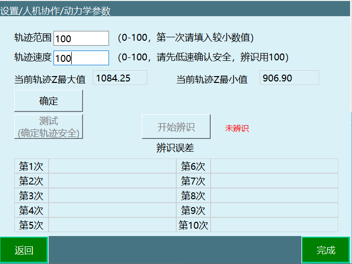
> 1.2 Parameter Description
- Trajectory range: Calculates the maximum and minimum motion range of the robot based on the trajectory range.
- Trajectory speed: The speed of the robot during operation, independent of the global speed.
- Current trajectory Z maximum/current trajectory Z minimum: Shows the Z range of the current trajectory.
- Identification error: After identification, six parameters appear, representing the error of the six axes respectively (the smaller the value, the smaller the error, and it cannot be 0).
> 1.3 Must-Read Before Use
| Warning |
|---|
| Currently, this identification method is only applicable to identifying the dynamic parameters of the robot body with a six-axis robot under no-load conditions. The dynamic parameters obtained by this identification method are unrelated to the manually filled dynamic parameters. Before performing identification, ensure the robot's motion range is open and free of obstacles. Among the identification trajectory parameters, the trajectory range is used to adjust the size of the robot's identification trajectory range: 100 is 100% of the identification trajectory, 90 is 90% of the identification trajectory, and so on. The trajectory speed is used to adjust the speed at which the robot executes the identification trajectory: at a speed of 100, the trajectory running time is 10 seconds; at a speed of 50, the trajectory running time is 20 seconds; at a speed of 10, the trajectory running time is 100 seconds, and so on. Selection principle of the identification trajectory parameters: under the premise of ensuring safety, make the motion range as large as possible and the motion speed as fast as possible. The error value obtained from the identification result corresponds to the sensitivity value in the collision detection function. Before identification, first try the low-speed, large-range trajectory parameters. Click the Test button to confirm that the robot will not hit the surrounding environment during operation. If this condition is not met, reduce the trajectory range parameter and run at low speed again to ensure it will not hit the surrounding environment. After confirming it will not hit the surrounding environment, set the trajectory speed to 100 and click the Identification button to start the robot parameter identification. When the test trajectory is safe, the robot runs two trajectory segments. Do not approach the robot before the test ends. During the identification trajectory, the robot runs two trajectory segments, 10 times. Do not approach the robot during this period; the robot may start at any time. The identification work is performed ten times in total, including processes such as running the trajectory, obtaining data, analyzing data and calculating dynamic parameters. After each completion, the error value is displayed on the screen. The entire process lasts about 30 minutes. Do not perform any operations during this period to avoid affecting the identification work. |
> 1.4 Operation Steps
Adjust the robot shutdown parameter - joint limits to ensure that all robot motion is within the safe range. All the following trajectories move within the limits.
Move the robot to the zero position.
Click [Settings - Human-Robot Collaboration - Dynamic Parameters] to enter the dynamic parameter screen.

- Carefully read the prompt description.
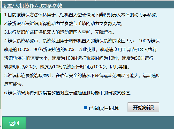
- After fully reading the prompt description, click "Read and Agree", then click "Start Identification".

- After entering the identification operation screen, fill in 10 for the trajectory range and 10 for the trajectory speed.
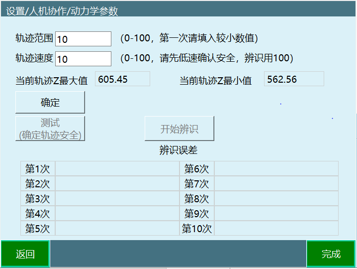
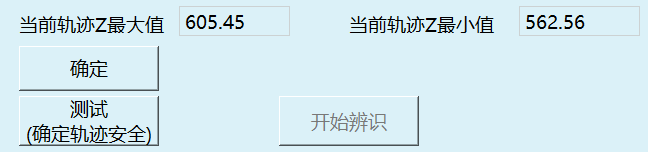
- Click "OK", view the current trajectory Z maximum and current trajectory Z minimum, check whether the range is reasonable, and confirm the trajectory is reachable before proceeding to the next step.
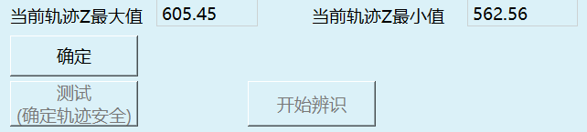
- Click "Test (Confirm Trajectory Safety)".
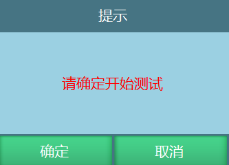
- A test prompt window pops up; click "Confirm".
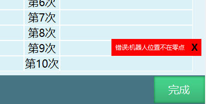
- If an error is reported, first return to the zero point as prompted.
- If no error is reported, a popup prompts "Testing...".
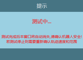
During robot motion, the robot can be stopped by pressing "Stop" in the upper right of the teach pendant, switching modes, or "pressing the emergency stop button".
After the test is completed, "Test Successful" is prompted.
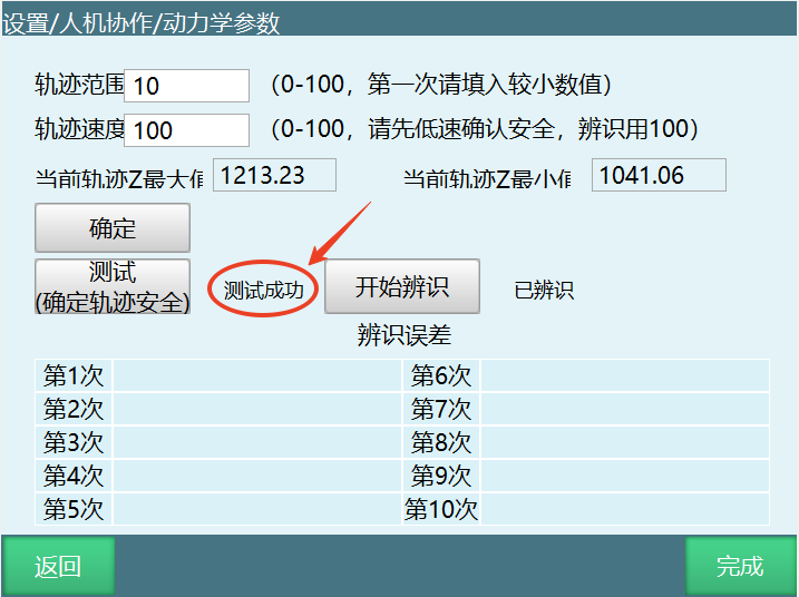
If the trajectory range is small, the trajectory range can be increased. In principle, the larger the trajectory range, the higher the identification accuracy.

The trajectory speed can be slow during testing, but during identification the trajectory speed must be set to 100.

On the basis of ensuring safety, maximize the trajectory range, and after adjusting the speed to 100, identification can begin.
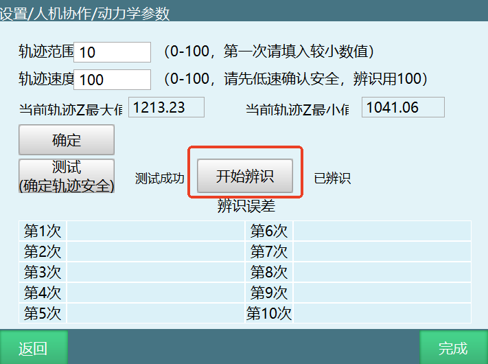
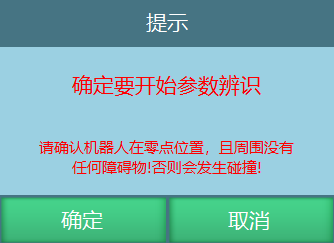
Click "Start Identification" (confirm the trajectory safety again, personnel stay away from the robot, and click Confirm).
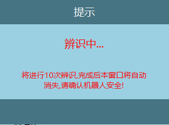
A popup prompts that identification is in progress. Do not approach the robot before the prompt that identification has ended. The robot may run the next trajectory segment at any time.
2. Mechanics Functions
The mechanics functions include collision detection and torque feedforward, which need to be set in "Settings/Human-Robot Collaboration/Mechanics Functions".
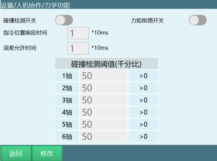
- Collision detection switch: When enabled, the robot detects collisions according to the sensitivity. Usually, the value at which a collision is not judged during robot operation needs to be found, and then it can be used normally.
- Command position response time: The robot body has already touched something during operation, but because this time is set, the error is delayed and reported according to the set time; when the time is up, the error appears and the robot powers off.
- Error tolerance time: PID adjustment causes torque fluctuations that falsely trigger the collision warning. This function prevents this phenomenon: if the torque returns to the normal range within the set time, the alarm does not appear.
> 2.1 Hand-Guiding Teaching
The drag method can be selected as torque or 3D mouse.
IO signals can be set to switch between drag mode and jog mode. Switching can also be done with the ⚪-shaped key of the teach pendant or the "Teach Method" button in the monitor window.

By triggering an external trigger signal, you can switch into drag mode (for example, if the signal trigger method is 0, it only takes effect when switching from 1 to 0. IO signals take priority; after IO triggering, the ⚪ key is ineffective).
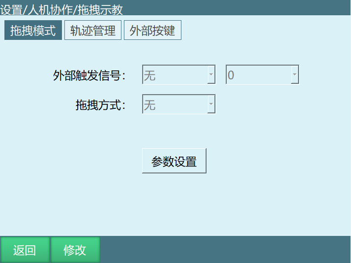
Click Modify and select 3D mouse as the drag method.
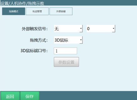
> 2.2 3D Mouse
2.2.1 Accessory Description
3D mouse related accessories:
- TTL to RS232 adapter
- 5V power supply
- 3D mouse body
- Cable storage box
- 3D mouse mounting plate
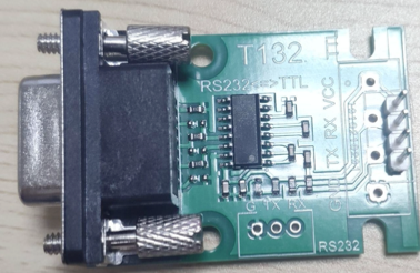
Wiring definitions:
- Power: TX-RX
- Controller: 3D mouse
- TTL-RS232 adapter: COM1-RX-TX
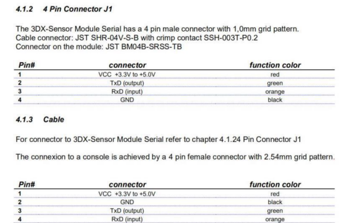
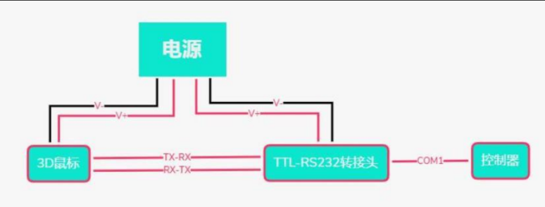
Wiring diagram: Same as above.
Installation: The installation parts of the 3D mouse are divided into the 3D mouse body, the 3D mouse cable box and the mounting plate.
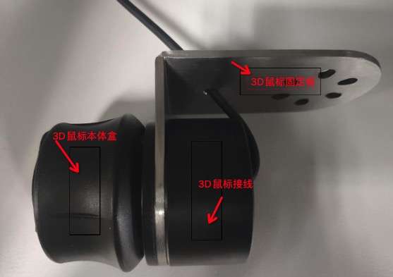
Among them, the 3D mouse cable box is used to store part of the 3D mouse connecting cable, and the mounting plate is used to mount the 3D mouse on the robot end. After assembling the 3D mouse components as shown in the figure above, it can be installed on the robot end. At the same time, the 3D mouse can also be used without being installed on the robot end, but in this case, the sense of direction when dragging is not as intuitive as when installed on the robot end.
Power supply device: External 5V power supply.
Wiring settings: Insert the mouse converter cable into the Com1 serial port of the controller, and the Com1 serial port needs to support RS232 communication.
> 2.3 Direct Use
Usage description and precautions:
- 3D mouse port number: Equivalent to the COM port on the controller. Fill in a number to select the corresponding COM port.

If the 3D mouse is installed on the robot body, be sure to confirm the robot operates safely before use!!!!!

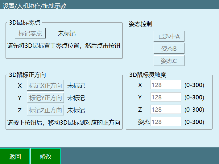
Mark zero point: Mark the zero position of the 3D mouse. Unmarked means the zero point has not been marked; after marking, it displays as marked.
Usage: click Modify, then click Mark Zero Point to complete the marking; there is no need to move the mouse.Mark positive directions: Divided into marking the X, Y and Z positive directions. Unmarked means the direction has not been marked; after marking, it displays as marked. If the communication fails after pressing, it displays communication failure; in this case, the direction follows the direction marked last time.
Usage: click Modify, then click the mark direction button, then press the corresponding direction of the mouse; when prompted that the direction is marked successfully, the marking of that direction is complete.Pose control: Select the pose controlled by the mouse rotation; poses A, B and C can be selected for control.
Usage: click Modify, then click the corresponding pose button to complete the selection.3D mouse sensitivity: Used to control the sensitivity of the 3D mouse in controlling the corresponding directions and poses.
Usage: click Modify and enter a value; the value range is 0-300. The larger the number, the higher the sensitivity.
Key sequence for first use:
- Click Modify
- Mark the zero point
- Mark the XYZ directions
- Set the sensitivity value
- Save
Methods for the 3D mouse to control robot motion:
- Complete the zero point setting and direction marking
- Enable the servo through the teach pendant
- Press the corresponding direction of the 3D mouse to control the robot to move in that direction
- The 3D mouse supports robot motion in all coordinate systems, but the direction correspondence only applies to the rectangular coordinate system. In other coordinate systems, it controls individual joint motion, which differs from the motion method in the rectangular coordinate system.
Torque drag: Note that dynamic identification must be performed before torque drag!
> 2.4 Parameter Description
2.4.1 Parameter Setting Screen
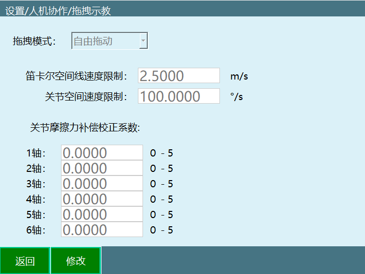
- Drag mode: Three modes can be selected: free drag, position drag and pose drag.
- Cartesian space linear velocity limit: Temporarily ineffective.
- Joint space speed limit: The maximum speed during dragging; after exceeding the limit, the robot powers off and stops.
- Joint friction compensation correction coefficient: Range 0-5. The closer the parameter is to 5, the more flexible the joints; it is recommended to start testing the parameter from 0.
2.4.2 Drag Mode Switching
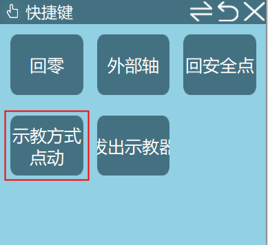
- Switch using the teach pendant - Monitor - Shortcut Keys - Jog Method button.
- Switch using the ⚪-shaped key of the teach pendant (the leftmost, bottom button).
- Switch using an external signal (DIN input signal).

Check whether the teach pendant status bar shows drag mode.

After entering drag mode, power on and the robot can be dragged.
2.4.3 Hand-Guiding Trajectory Playback
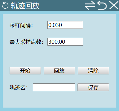
- Sampling interval: Unit s. A point is taken every sampling interval.
- Maximum number of sampling points: Range 200~12000. The maximum number of points of a recorded trajectory segment.
Operation steps: Enter the Monitor - Trajectory Playback screen.
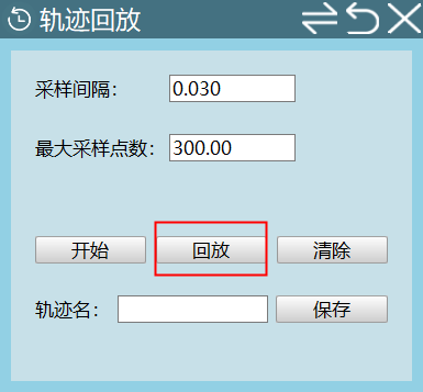
Switch to drag mode and set the sampling interval and maximum number of sampling points.
- Power on, click the Start button in the monitor popup, and start dragging the robot
- Click Stop or wait for the point recording to complete; the screen displays that the trajectory has been recorded
- At this time, you can power off, switch to jog mode, and click the Playback button to play back the just-dragged trajectory
- Enter the trajectory name and click Save to save the just-recorded trajectory
- Clear: clear the recorded trajectory
2.4.4 Trajectory Management
Enter the Settings - Human-Robot Collaboration - Hand-Guiding Teaching - Trajectory Management screen.
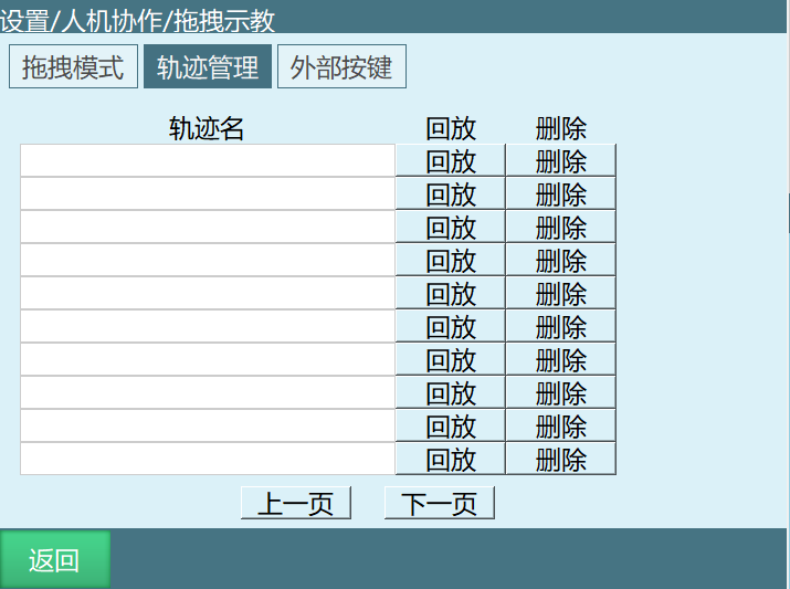
Saved trajectories can be played back and deleted here.
2.4.5 External Keys
On the external keys screen, the robot's drag/jog mode, start/end trajectory collection, start/stop trajectory playback, enable/disable and other functions can be controlled through the set trigger ports, parameters and methods.
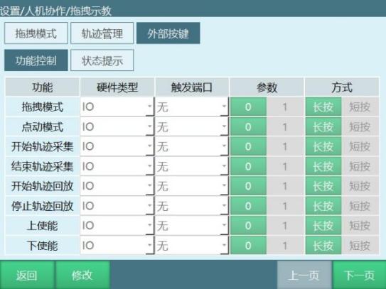
(Note: The same type can use the same trigger port. The trigger signal must be a rising edge or falling edge to be effective. A long press requires continuous input of 3-10)
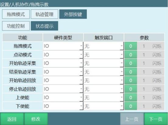
When the corresponding function is satisfied, the status prompt screen makes the IO react according to the set trigger port and parameter type.
> 2.5 Hand-Guiding Teaching Instructions
DRAG_TRAJECTORY instruction
This instruction is used to invoke trajectory playback recordings. When the playback rate is filled with 100%, it means the speed of the current drag; 500% means five times the current drag speed, and so on.
Note: The running speed of this instruction is drag speed x playback rate; the status bar speed does not affect the speed of this instruction.

> 2.6 Adaptive Acceleration/Deceleration
When the adaptive acceleration/deceleration enable is turned on, the motor can be protected, preventing excessive torque during motor motion (only supports four-axis Scara robots).
To set adaptive acceleration/deceleration, enter "Settings/Human-Robot Collaboration/Adaptive Acceleration/Deceleration" for the settings. The relevant steps are as follows:
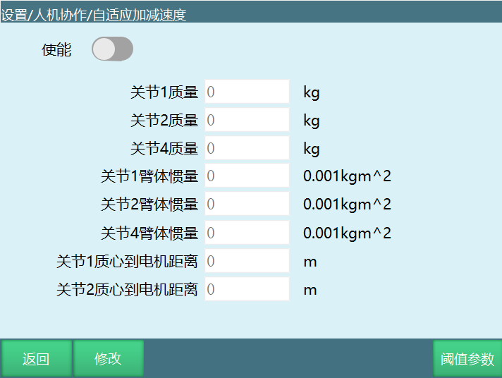
Fill in the corresponding parameters according to your own needs; it takes effect after turning on the enable switch.
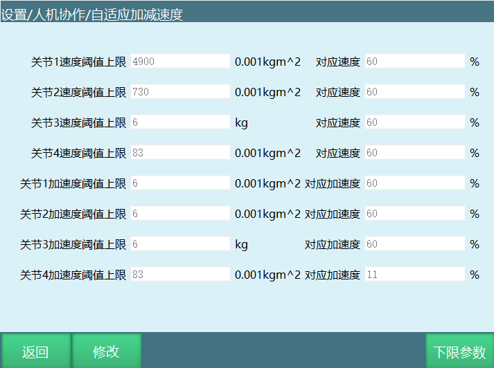
Threshold parameters: The screen for filling in the upper and lower limits of speed and acceleration.
> 2.7 Load Hand-Guiding Teaching Flow
- Perform identification according to the dynamic parameter flow
- Install the load after successful identification
- Then set the parameters on the hand-guiding teaching screen; the drag method can be torque or 3D mouse
To switch between drag mode and jog mode, the ⚪-shaped key of the teach pendant, the Monitor "Teach Method" button and external trigger IO signals can be used.
| Note |
|---|
| After switching to drag mode via IO signals, the ⚪-shaped button and the "Teach Method" button are ineffective. |
- Finally, set the load enable parameters (the load parameters are set on the tool screen and the load enable screen respectively), turn on the load enable switch, save, then switch the teach pendant from jog mode to drag mode; after power-on, dragging can be performed.
(1) Load enable screen settings as follows: Settings — Human-Robot Collaboration — Load Enable.
- Load enable: Whether to enable the load function. After turning on the load enable, the system calculates the loaded torque of the arm during operation based on the load parameters under the selected load number.
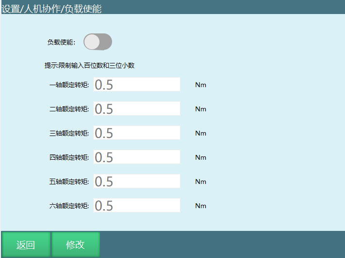
- Rated torque: The rated torque of each joint motor (refer to the rated torque in the servo parameters).
(2) Tool screen settings as follows: Settings — Tool Calibration.
Load number (i.e., tool number): The tool number is the load number.
Load mass: The total mass of the robot end load.
Load inertia: The moment of inertia of the load.
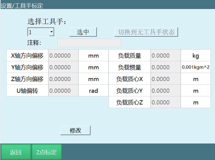
The following XYZ all use the end coordinate system as the reference (method for confirming the end coordinate system axes: with no tool, move TX, TY, TZ in the tool coordinate system to confirm the XYZ directions).
- X: Starting from the flange center, the offset (distance) of the load center of mass along the X direction.
- Y: Starting from the flange center, the offset (distance) of the load center of mass along the Y direction.
- Z: Starting from the flange center, the offset (distance) of the load center of mass along the Z direction.
Supplementary explanation of XYZ: It is recommended that after installing the load, at the robot's zero position, adjust the six-axis zero point so that the load center of mass is directly in front of the robot. At this time, X is the horizontal distance between the load center of mass and the six-axis center, Z is the vertical distance between the load center of mass and the six-axis center, and Y is 0.
| Note |
|---|
| For the above specific parameters, please consult the manufacturer. |
3. Q&A
Q: What is Human-Robot Collaboration (HRC)?
A: Human-Robot Collaboration (HRC) refers to a working method in which humans and automated machines share a workspace and perform operations at the same time.
Q: What scenarios does dynamic parameter identification apply to?
A: Currently, this identification method is only applicable to identifying the dynamic parameters of the robot body with a six-axis robot under no-load conditions.
Q: What preparations are needed before dynamic parameter identification?
A: Adjust the joint limits in the robot shutdown parameters to ensure all robot motion is within the safe range; move the robot to the zero position; ensure the robot's motion range is open and free of obstacles.
Q: What do the trajectory range and trajectory speed in the identification trajectory parameters mean?
A: The trajectory range is used to adjust the size of the robot's identification trajectory range: 100 is 100% of the identification trajectory, 90 is 90% of the identification trajectory, and so on; the trajectory speed is used to adjust the speed at which the robot executes the identification trajectory: at a speed of 100, the trajectory running time is 10 seconds; at a speed of 50, the trajectory running time is 20 seconds; at a speed of 10, the trajectory running time is 100 seconds, and so on.
Q: What is the selection principle of the identification trajectory parameters?
A: Under the premise of ensuring safety, make the motion range as large as possible and the motion speed as fast as possible.
Q: What is the purpose of the error value obtained from the identification result?
A: The error value obtained from the identification result corresponds to the sensitivity value in the collision detection function.
Q: How long does the identification work take?
A: The identification work is performed ten times in total, including processes such as running the trajectory, obtaining data, analyzing data and calculating dynamic parameters. The entire process lasts about 30 minutes.
Q: What should be done when the test trajectory is safe?
A: Before identification, first try the low-speed, large-range trajectory parameters. Click the Test button to confirm that the robot will not hit the surrounding environment during operation. If this condition is not met, reduce the trajectory range parameter and run at low speed again to ensure it will not hit the surrounding environment. After confirming it will not hit the surrounding environment, set the trajectory speed to 100 and click the Identification button to start the robot parameter identification. When the test trajectory is safe, the robot runs two trajectory segments; do not approach the robot before the test ends.
Q: What is the difference between the trajectory speed during testing and during identification?
A: The trajectory speed can be slow during testing, but during identification the trajectory speed must be set to 100.
Q: What is the purpose of the collision detection switch?
A: When enabled, the robot detects collisions according to the sensitivity. Usually, the value at which a collision is not judged during robot operation needs to be found, and then it can be used normally.
Q: What is the purpose of the command position response time?
A: The robot body has already touched something during operation, but because this time is set, the error is delayed and reported according to the set time; when the time is up, the error appears and the robot powers off.
Q: What is the purpose of the error tolerance time?
A: PID adjustment causes torque fluctuations that falsely trigger the collision warning. This function prevents this phenomenon: if the torque returns to the normal range within the set time, the alarm does not appear.
Q: What drag methods does hand-guiding teaching support?
A: The drag method can be selected as torque or 3D mouse.
Q: How do I switch between drag mode and jog mode?
A: IO signals can be set to switch between drag mode and jog mode. Switching can also be done with the ⚪-shaped key of the teach pendant or the "Teach Method" button in the monitor window.
Q: How does the external trigger signal take effect?
A: By triggering an external trigger signal, you can switch into drag mode (for example, if the signal trigger method is 0, it only takes effect when switching from 1 to 0. IO signals take priority; after IO triggering, the ⚪ key is ineffective).
Q: What accessories does the 3D mouse have?
A: The 3D mouse related accessories include: TTL to RS232 adapter, 5V power supply, 3D mouse body, cable storage box and 3D mouse mounting plate.
Q: How should the 3D mouse be wired?
A: Insert the mouse converter cable into the Com1 serial port of the controller, and the Com1 serial port needs to support RS232 communication.
Q: What is the key sequence for the first use of the 3D mouse?
A: 1. Click Modify; 2. Mark the zero point; 3. Mark the XYZ directions; 4. Set the sensitivity value; 5. Save.
Q: How does the 3D mouse control robot motion?
A: 1. Complete the zero point setting and direction marking; 2. Enable the servo through the teach pendant; 3. Press the corresponding direction of the 3D mouse to control the robot to move in that direction; 4. The 3D mouse supports robot motion in all coordinate systems, but the direction correspondence only applies to the rectangular coordinate system. In other coordinate systems, it controls individual joint motion, which differs from the motion method in the rectangular coordinate system.
Q: What is torque drag?
A: Torque drag is a method of hand-guiding teaching. Dynamic identification must be performed before use.
Q: What drag modes are there?
A: The drag mode can select three modes: free drag, position drag and pose drag.
Q: What is the range of the joint friction compensation correction coefficient?
A: Range 0-5. The closer the parameter is to 5, the more flexible the joints; it is recommended to start testing the parameter from 0.
Q: After switching to drag mode via IO signals, are other switching methods still effective?
A: After switching to drag mode via IO signals, the ⚪-shaped button and the "Teach Method" button are ineffective.
Q: What does the sampling interval of trajectory playback mean?
A: Unit s. A point is taken every sampling interval.
Q: What is the range of the maximum number of sampling points for trajectory playback?
A: Range 200~12000. The maximum number of points of a recorded trajectory segment.
Q: How do I perform hand-guiding trajectory playback?
A: Enter the Monitor - Trajectory Playback screen, switch to drag mode, set the sampling interval and maximum number of sampling points, then power on and click the Start button in the monitor popup to start dragging the robot. Click Stop or wait for the point recording to complete, then power off and switch to jog mode, click the Playback button to play back the just-dragged trajectory. You can also enter a trajectory name and click Save to save the just-recorded trajectory.
Q: What functions can the external keys control?
A: They can control the robot's drag/jog mode, start/end trajectory collection, start/stop trajectory playback, enable/disable and other functions.
Q: What is the purpose of the DRAG_TRAJECTORY instruction?
A: This instruction is used to invoke trajectory playback recordings. When the playback rate is filled with 100%, it means the speed of the current drag; 500% means five times the current drag speed, and so on. The running speed of this instruction is drag speed x playback rate; the status bar speed does not affect the speed of this instruction.
Q: Which robots does the adaptive acceleration/deceleration function apply to?
A: When the adaptive acceleration/deceleration enable is turned on, the motor can be protected, preventing excessive torque during motor motion (only supports four-axis Scara robots).
Q: What is the load hand-guiding teaching flow?
A: 1. Perform identification according to the dynamic parameter flow; 2. Install the load after successful identification; 3. Then set the parameters on the hand-guiding teaching screen; the drag method can be torque or 3D mouse; 4. Finally, set the load enable parameters (the load parameters are set on the tool screen and the load enable screen respectively), turn on the load enable switch, save, then switch the teach pendant from jog mode to drag mode; after power-on, dragging can be performed.
Q: What is the purpose of the load enable in the load enable parameters?
A: Whether to enable the load function. After turning on the load enable, the system calculates the loaded torque of the arm during operation based on the load parameters under the selected load number.
Q: Which load parameters need to be set on the tool calibration screen?
A: The load number (i.e., tool number), load mass (the total mass of the robot end load), load inertia (the moment of inertia of the load), and the offset distances of the load center of mass relative to the flange center in the X, Y and Z directions.
Q: How are the XYZ parameters of the load center of mass defined?
A: The following XYZ all use the end coordinate system as the reference. X: starting from the flange center, the offset (distance) of the load center of mass along the X direction; Y: starting from the flange center, the offset (distance) of the load center of mass along the Y direction; Z: starting from the flange center, the offset (distance) of the load center of mass along the Z direction.
Q: How are the XYZ parameters of the load center of mass recommended to be determined?
A: It is recommended that after installing the load, at the robot's zero position, adjust the six-axis zero point so that the load center of mass is directly in front of the robot. At this time, X is the horizontal distance between the load center of mass and the six-axis center, Z is the vertical distance between the load center of mass and the six-axis center, and Y is 0.
Q: What should be done if the specific load parameters are unknown?
A: For the above specific parameters, please consult the manufacturer.