Tool Hand Calibration
Tool Coordinate System
What is the Tool Coordinate System?
Flange Center: The origin of the default tool coordinate system, the direction from the flange center to the flange positioning hole is the +X direction, perpendicular to the flange outward is the +Z direction, and finally the Y direction can be determined according to the right-hand rule. New tool coordinate systems are obtained by changing relative to the default tool coordinate system.
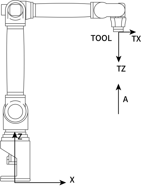
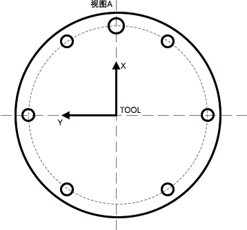
Why establish a tool coordinate system?
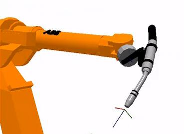
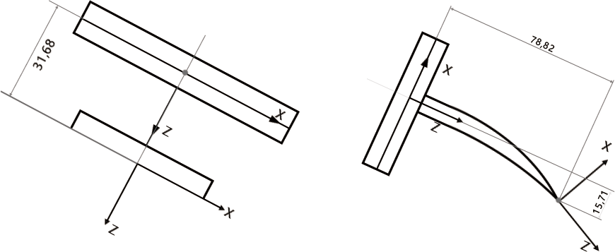
- The robot has a default tool coordinate system Tool 0: position at the flange center. However, in actual motion, the robot often installs suction cups (as shown in Figure 1), welding torches (as shown in Figure 2), and other tools at the flange center. At this time, if the robot motion center is still at the flange center, it will cause great inconvenience. Therefore, it is necessary to teach the required tool coordinate system according to actual conditions.
For example: During welding, a welding torch needs to be installed at the robot end (flange center), users usually define the TCP point to the tip of the welding wire. Then the position recorded in the program is the position of the welding wire tip, and the recorded attitude is the attitude of the welding torch rotating around the welding wire tip.
- For industrial robots, tools need to be installed on the end flange for operations. In order to determine the pose of the tool, bind a tool coordinate TCS (Tool Coordinate System) on the installed workpiece, the origin of TCS is TCP (Tool Center Point, tool center point).
TCP: TOOL CENTER POINT, i.e., tool center point.
Robot trajectory and speed: refers to the trajectory and speed of the TCP point.
TCP is generally set at the center of the gripper, the end of the welding wire, the front of the spot welding static arm, etc.
Industrial robots generally define a TCP in advance, the XY plane of TCP is bound to the flange plane of the robot's sixth axis, and the origin of TCP coincides with the flange center. Obviously, TCP is at the flange center. ABB robots call TCP Tool0, REIS robots call it _tnull. Although the default TCP can be used directly, in actual use, such as welding, users usually define the TCP point to the tip of the welding wire (actually the pose of the welding torch Tool coordinate system in the Tool0 coordinate system), then the position recorded in the program is the position of the welding wire tip, and the recorded attitude is the attitude of the welding torch rotating around the welding wire tip.
Tool Coordinate System Characteristics:
The new tool coordinate system is obtained by changing relative to the default tool coordinate system. The position and direction of the new tool coordinate system always maintain an absolute position and attitude relationship with the flange, but it is constantly changing in space.
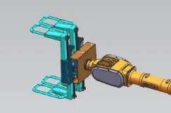 | 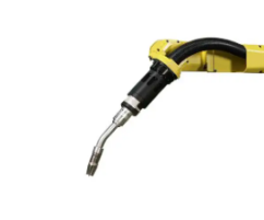 |
|---|---|
| X | ✓ |
Note: For cases where the tool has no tip and cannot be aligned with the calibration cone, use the gripper to hold a specific pointed object for calibration. The calibration accuracy depends on how the pointed object is placed.
How to choose the calibration method when the robot body parameters are accurate:
| Calibration Method | Function | Applicable Conditions |
|---|---|---|
| 6-point calibration | Calibrate tool hand size Calibrate tool hand tip attitude | When robot parameters are accurate: calibrate tool hand size + attitude, calibration result has better accuracy for C axis rotation |
| 7-point calibration | Calibrate tool hand size Calibrate tool hand tip attitude | When robot parameters are accurate: calibrate tool hand size + attitude, calibration result has better accuracy for A, B axis rotation |
| 12-point calibration | Correct zero point for axes 2, 3, 4, 5 Calibrate tool hand size | Calibrate zero point + calibrate tool size |
| 15-point calibration | Correct zero point for axes 2, 3, 4, 5 Calibrate tool hand size Calibrate tool hand tip attitude | Calibrate zero point + calibrate tool size + calibrate tool attitude |
| 20-point calibration | Correct zero point for axes 2, 3, 4, 5 Calibrate tool hand size | First use calibration cone to calibrate 20 points to correct zero point, then use tool hand to calibrate 6, 7 points |
Applicable Scenarios
When the robot's X, Y, Z axes need to rotate around the A, B, C attitude axes during work, tool hand calibration is needed, such as welding process, polishing process, spraying process, etc.
How to choose tool hand calibration method in different scenarios
- Robot has done laser calibration + using welding torch.
Recommendation: Use 6-point calibration for tool hand, verify the robot calibration results after calibration is complete.
- Robot has not done laser calibration + using welding torch.
Recommendation: Use 12-point calibration for tool hand, verify the robot calibration results after calibration is complete.
- Calibrating palletizing gripper.
Recommendation: Prioritize directly filling in tool dimensions, use 6-point calibration if dimensions are unknown.
How to do 6-point calibration?
Prepare a pointed object that can be gripped by the gripper, place the object as close to the gripper center as possible, then find a calibration cone with a tip, and perform tool hand calibration according to the 6-point calibration steps.
- Robot zero point lost, zero point position calibrated according to alignment holes has deviation.
Recommendation: Prepare calibration tool, the tool tip should be as close to the center extension line of the 6th axis flange as possible, tool dimensions should be small;
Use 20-point calibration to correct zero point;
After 20-point calibration, change to the actual tool hand to be used for 6-point calibration;
Verify the robot calibration results after calibration is complete.
- After 6-point calibration, A, B axis rotation error is large and cannot meet usage requirements.
Recommendation: Change to 7-point calibration.
- How to verify calibration accuracy?
In teach mode, align the tool hand calibration tip with the calibration cone, when the tips are aligned, select the calibrated tool hand parameters, switch the jog coordinate system to Cartesian, jog the A, B, C axes, and check if the tips are aligned and how many mm they are offset.
- How to fill in gripper dimensions?
Prepare the gripper length, width, and height parameters,
Fill the gripper tip offset on the X axis into "X axis direction offset".
If the tip is in the positive direction of the Cartesian X axis, fill in a positive value. Fill the gripper tip offset on the Y axis into "Y axis direction offset".
If the tip is in the positive direction of the Cartesian Y axis, fill in a negative value. Fill the gripper tip offset on the Z axis into "Z axis direction offset".
If the tip is in the positive direction of the Cartesian Z axis, fill in a negative value. After saving, verify the tool hand rotation A, B, C accuracy.
Tool Hand Parameters
Enter Settings - Tool Hand Calibration interface to select the tool hand, directly select the tool hand number in the left dropdown box, click the tool calibration in the lower right corner to enter the calibration interface.
After the calibration results are saved, the X axis direction offset, Y axis direction offset, Z axis direction offset in the tool hand parameters of this interface will have values, these are the error values compared to the current values after calibration.
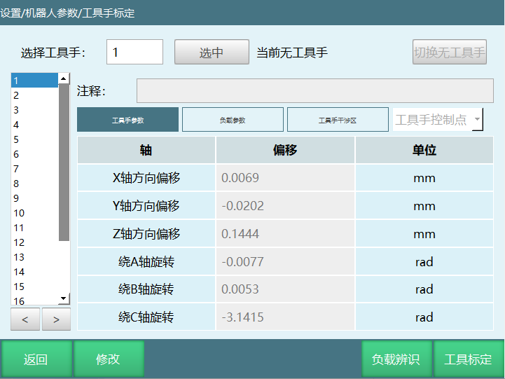
Tool hand parameters:
| Axis | Offset | Unit |
|---|---|---|
| X Axis | Offset length of tool end relative to flange center along the X axis of Cartesian coordinate system | Millimeters (mm) |
| Y Axis | Offset length of tool end relative to flange center along the Y axis of Cartesian coordinate system | Millimeters (mm) |
| Z Axis | Offset length of tool end relative to flange center along the Z axis of Cartesian coordinate system | Millimeters (mm) |
| A Axis | Rotation angle of tool end relative to flange center around the X axis of Cartesian coordinate system | Degrees/Radians (°/rad) |
| B Axis | Rotation angle of tool end relative to flange center around the Y axis of Cartesian coordinate system | Degrees/Radians (°/rad) |
| C Axis | Rotation angle of tool end relative to flange center around the Z axis of Cartesian coordinate system | Degrees/Radians (°/rad) |
Have detailed parameters of installed tool:
Select the tool hand number, click [Modify], then fill in the installed tool hand parameters;
Click [OK];
Click [Select], at this time the tool hand number displayed in the toolbar above the status bar is the selected tool number;
On this interface, users can directly fill in the relevant parameters of tool end offset without performing tool hand calibration. If the tool hand is changed, please fill in again;
Detailed calibration process is as follows:
6-Point Calibration
Enter Settings - Robot Parameters - Tool Hand Calibration - Tool Calibration - Calibrate Tool Size + Attitude, the calibration method can choose 6-point method, as shown in the figure:
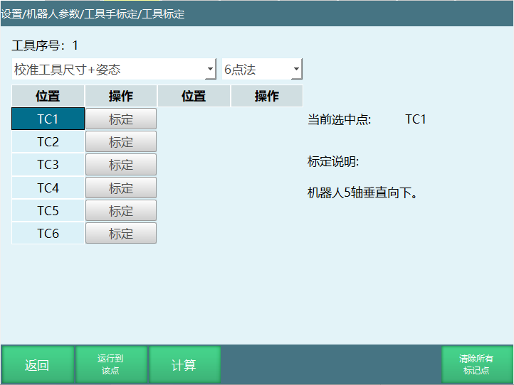
After 6-point calibration ends, select any calibrated point, click [Run to This Point], you can check if the calibration is accurate;
Click the [Calculate] button, calibration is successful. Click the [Return] button at the bottom to return to the "Tool Hand Calibration" interface, rotating around ABC can check if the calibrated points are correct;
If you are not satisfied with a certain point during calibration, you can click the [Cancel Calibration] button corresponding to that row, cancel the calibration and calibrate that point again.
Click the [Return] button at the bottom to return to "Tool Hand Calibration" interface.
Calibration method is shown in the figure:
TCP1: Robot 5th axis vertical downward;
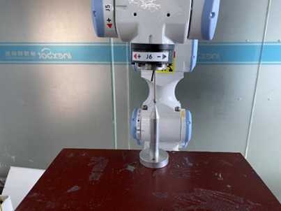
TCP2: Robot rotates C axis to 180° based on the first point;
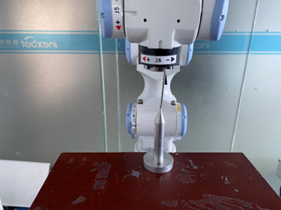
TCP3: Robot rotates B axis to 35° based on the first point;
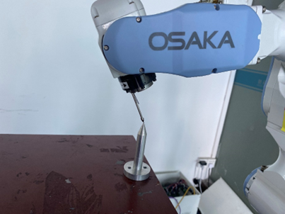
TCP4: Robot returns to zero point, then tool hand tip is vertical;
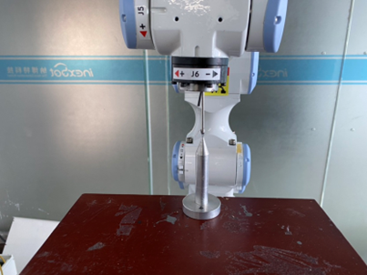
TCP5: Robot moves X- based on the fourth point;
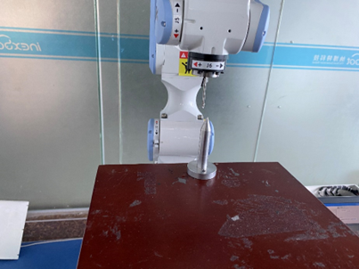
TCP6: Robot moves Y+ based on the fifth point.
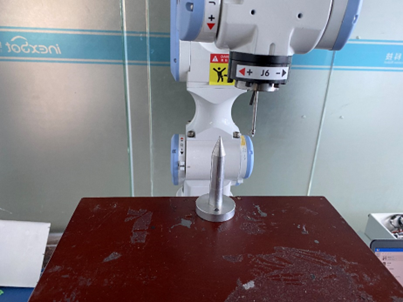
[Calculate]: After six points are calibrated, click "Calculate" to calculate the result. If the calculation result is greater than 1, recalibration is needed.
[Run to This Point]: Select any marked point, click "Run to This Point" the robot will run to the selected position.
[Clear All Marked Points]: Clear all 6 marked points.
[Return]: Return to "Tool Hand Calibration" interface.
If you are not satisfied with a certain point during calibration, you can click the [Cancel Calibration] button corresponding to that row, cancel the calibration and calibrate that point again.
How to verify calibration accuracy:
In teach mode, align the tool hand calibration tip with the calibration cone, when the tips are aligned, select the calibrated tool hand parameters, switch the jog coordinate system to Cartesian, jog the A, B, C axes, and check if the tips are aligned and how many mm they are offset.
7-Point Calibration
Click Calibrate Tool Size + Attitude - 7-point method to enter the 7-point calibration interface, as shown in the figure.
Click [Run to This Point], you can check if the calibration is accurate;
Click the [Calculate] button, calibration is successful;
Click [Clear All Marked Points] to clear all calibrated values and recalibrate;
If you are not satisfied with a certain point after calibration, you can click the [Cancel Calibration] button corresponding to that row, cancel the calibration and calibrate that point again.
Click the [Return] button at the bottom to return to "Tool Hand Calibration" interface.
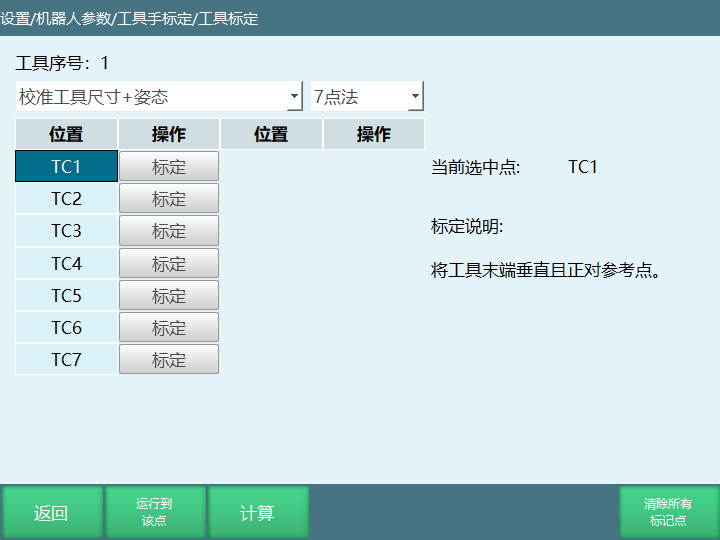
If there are no detailed parameters of the tool, TCP calibration can be performed to automatically calculate various tool size parameters. Specific calibration steps are as follows:
Now use the pen tip as the reference point, and ensure this reference point is fixed, as shown in the figure below.
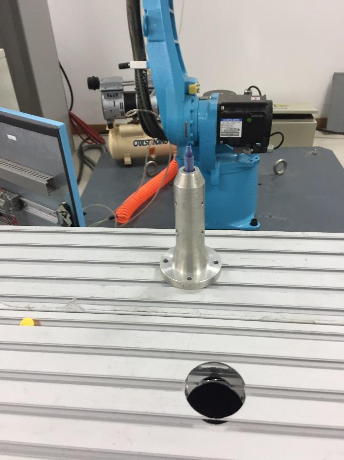
TCP1: Align the tool end vertically and facing the reference point, click the [Calibrate] button corresponding to "TCP1" on the interface, as shown in the figure below:
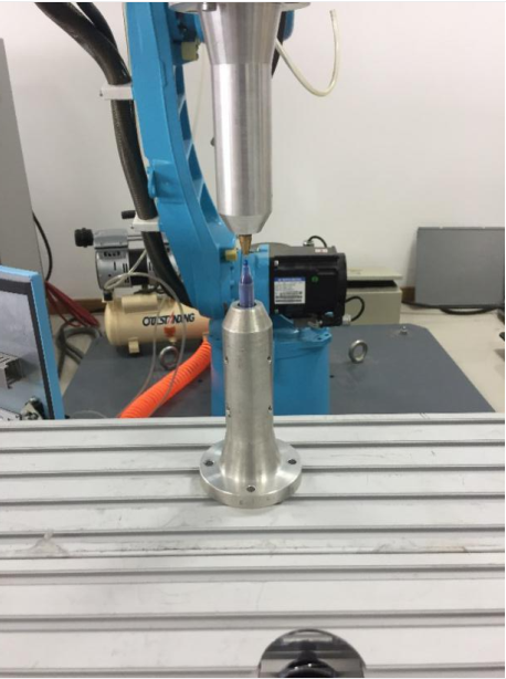
TCP2: Switch the robot to a different posture, align the end facing the reference point, click the [Calibrate] button corresponding to that row, as shown in the figure below:
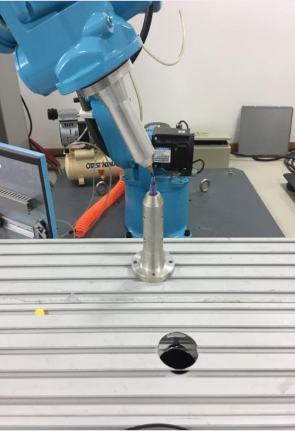
TCP3: Switch the robot to a different posture, align the end facing the reference point, click the [Calibrate] button corresponding to that row, as shown in the figure below:
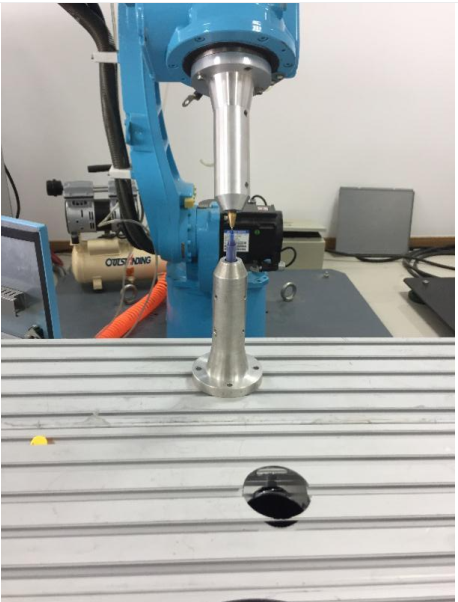
TCP4: Switch the robot to a different posture, align the end facing the reference point, click the [Calibrate] button corresponding to that row, as shown in the figure below:
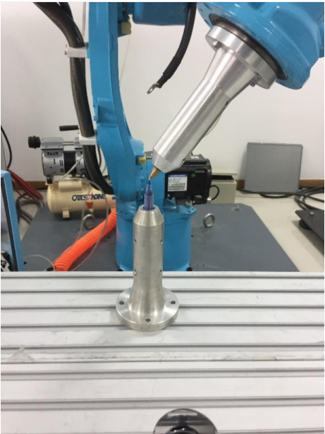
TCP5: Align the tool end vertically and facing the reference point (same as TCP1), click the [Calibrate] button corresponding to that row, as shown in the figure below:
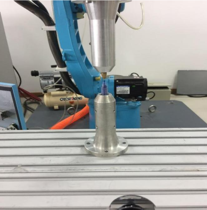
TCP6: Based on TCP5, move any distance in the negative direction of the Cartesian coordinate system X axis, click the [Calibrate] button corresponding to that row, as shown in the figure below:
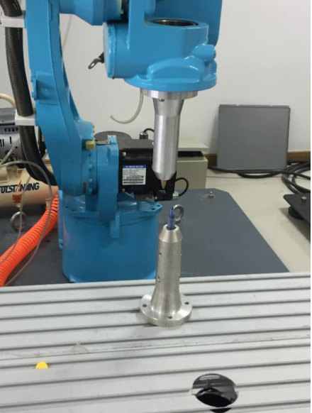
TCP7: Based on TCP6, move any distance in the positive direction of the Cartesian coordinate system Y axis, click the [Calibrate] button corresponding to that row, as shown in the figure below:
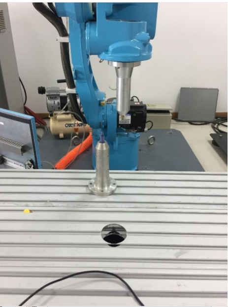
[Calculate]: After seven points are calibrated, click "Calculate" to calculate the result. If the calculation result is greater than 1, recalibration is needed.
[Run to This Point]: Select any marked point, click "Run to This Point" the robot will run to the selected position.
[Clear All Marked Points]: Clear all 7 marked points.
[Return]: Return to "Tool Hand Calibration" interface.
If you are not satisfied with a certain point during calibration, you can click the [Cancel Calibration] button corresponding to that row, cancel the calibration and calibrate that point again.
12-Point Calibration
12-point calibration result only has the XYZ axis direction offset of the tool hand, no values for rotation around ABC. Click "Tool Calibration" - Calibrate Zero Point + Tool Size - 12-point method to enter the calibration interface, as shown in the figure:
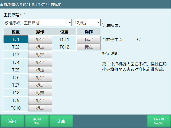
Specific calibration steps are as follows:
Find a reference point (calibration cone tip as reference point), and ensure this reference point is fixed;
Start inserting position points, for each point inserted, click [Mark This Point].
Specific steps are as follows:
TCP1: First point robot returns to zero point, align the robot tip with the calibration cone tip through Cartesian coordinates, calibrate the first point;
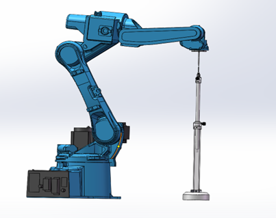
TCP2: Second point based on the first point, rotate C 180 degrees through Cartesian coordinate system; align tips to calibrate the second point;
TCP3: Third point robot returns to zero point, align the robot tip with the calibration cone tip through Cartesian coordinate system; calibrate the third point (same as the first point);
TCP4: Fourth point based on the third point, do B- through Cartesian coordinate system, degree between 30°-60°, align tips to calibrate the fourth point;
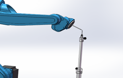
TCP5: Fifth point based on the fourth point, do B+ through Cartesian coordinate system, J5>-90°, align the robot tip with the calibration cone tip, calibrate the fifth point;
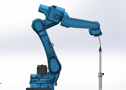
TCP6: Sixth point select the first point, and move the robot to the first point, based on the first point, do B+ through Cartesian coordinate system, J5>-90°, align tips to calibrate the sixth point;
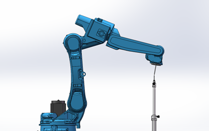
TCP7: Seventh point based on the first point, do B- through Cartesian coordinate system, J5>-90°, align tips to calibrate the seventh point;
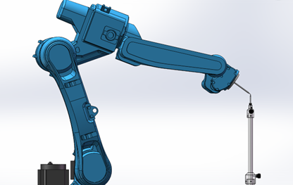
TCP8: Eighth point based on the seventh point, do A+ through Cartesian coordinate system, rotate 90°, J5>-90°, align tips to calibrate the eighth point;
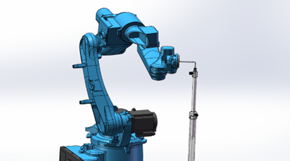
TCP9: Ninth point based on the seventh point, do A- through Cartesian coordinate system, rotate 90°, J5>-90°, align tips to calibrate the ninth point;
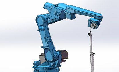
TCP10: Tenth point robot returns to the first point, jog the fifth axis through joint coordinate system, make the fifth axis upward, J5<-90°, align the tips, calibrate the tenth point;
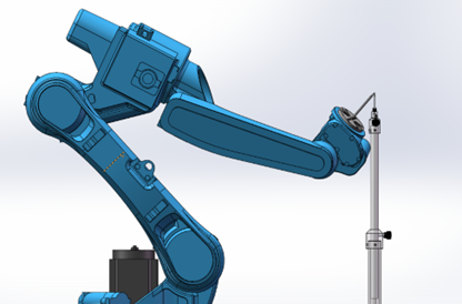
TCP11: Eleventh point robot based on the tenth point, do A+ through Cartesian coordinate system, rotate 90°, J5<-90°, align tips to calibrate the eleventh point;
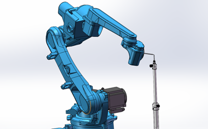
TCP12: Twelfth point robot based on the tenth point, do A- through Cartesian coordinate system, rotate 90°, J5<-90°, align tips to calibrate the twelfth point;
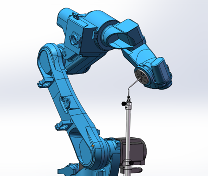
After marking is complete, click [Calculate].
[Cancel Calibration]: If you are not satisfied with a certain point after calibration, you can click the [Cancel Calibration] button corresponding to that row, cancel the calibration and calibrate that point again;
[Run to This Point]: After each point is calibrated, you can click [Run to This Point], the robot will run to that point;
[Mark Result Position as Zero Point]: Set the calibration compensation position as the current robot's zero point position;
[Clear All Calibration Points]: Calibration points will be saved to the controller, the calibration results will only be cleared after clicking cancel calibration, clearing all calibration points, or switching tool hand to enter calibration interface.
Click the [Return] button at the bottom to return to "Tool Hand Calibration" interface.
15-Point Calibration
15-point calibration result only has the XYZ axis direction offset of the tool hand, no values for rotation around ABC. Click "Tool Calibration" - Calibrate Zero Point + Tool Size + Attitude - 15-point method to enter the calibration interface, as shown in the figure.
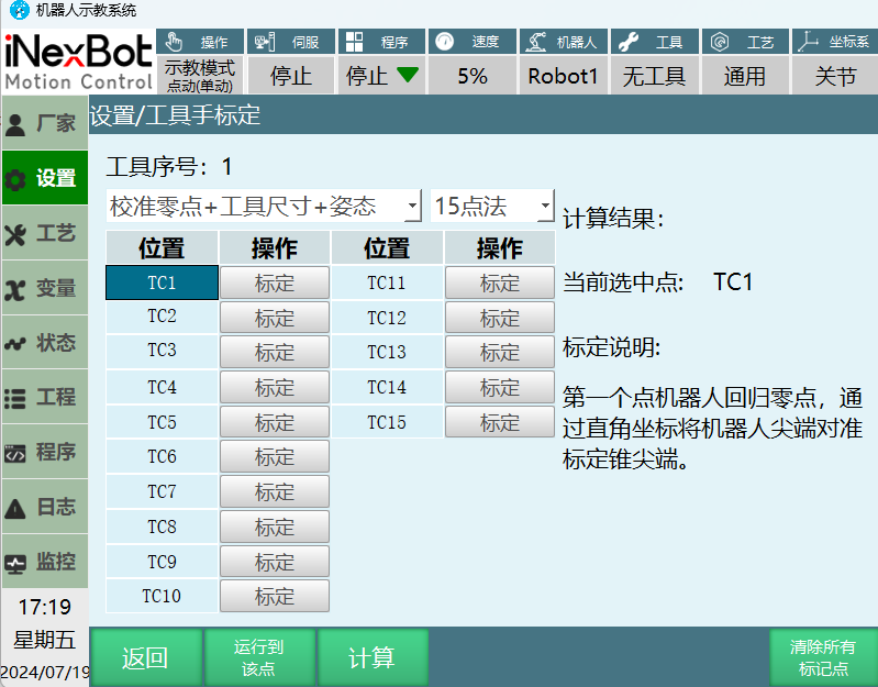
Specific calibration steps are as follows:
Find a reference point (calibration cone tip as reference point), and ensure this reference point is fixed;
Start inserting position points, for each point inserted, click [Mark This Point], insert fifteen points.
Specific steps are as follows:
TCP1: First point robot returns to zero point, align the robot tip with the calibration cone tip through Cartesian coordinates, calibrate the first point;
TCP2: Second point based on the first point, rotate C 180 degrees through Cartesian coordinate system; align tips to calibrate the second point;
TCP3: Third point robot returns to zero point, align the robot tip with the calibration cone tip through Cartesian coordinate system; calibrate the third point (same as the first point);
TCP4: Fourth point based on the third point, do B- through Cartesian coordinate system, degree between 30°-60°, align tips to calibrate the fourth point;
TCP5: Fifth point based on the fourth point, do B+ through Cartesian coordinate system, J5>-90°, align the robot tip with the calibration cone tip, calibrate the fifth point;
TCP6: Sixth point select the first point, and move the robot to the first point, based on the first point, do B+ through Cartesian coordinate system, J5>-90°, align tips to calibrate the sixth point;
TCP7: Seventh point based on the first point, do B- through Cartesian coordinate system, J5>-90°, align tips to calibrate the seventh point;
TCP8: Eighth point based on the seventh point, do A+ through Cartesian coordinate system, rotate 90°, J5>-90°, align tips to calibrate the eighth point;
TCP9: Ninth point based on the seventh point, do A- through Cartesian coordinate system, rotate 90°, J5>-90°, align tips to calibrate the ninth point;
TCP10: Tenth point robot returns to the first point, jog the fifth axis through joint coordinate system, make the fifth axis upward, J5<-90°, align the tips, calibrate the tenth point;
TCP11: Eleventh point robot based on the tenth point, do A+ through Cartesian coordinate system, rotate 90°, J5<-90°, align tips to calibrate the eleventh point;
TCP12: Twelfth point robot based on the tenth point, do A- through Cartesian coordinate system, rotate 90°, J5<-90°, align tips to calibrate the twelfth point;
TCP13: Thirteenth point robot returns to zero point position, adjust robot posture, make the robot end tool tip vertical downward, align the calibration tip with the calibration cone, calibrate the thirteenth point;
TCP14: Fourteenth point robot based on the thirteenth point, do X- through Cartesian coordinate system, robot moves a certain distance, directly click to calibrate the fourteenth point;
TCP15: Fifteenth point robot based on the fourteenth point, do Y+ through Cartesian coordinate system, robot moves a certain distance, directly click to calibrate the fifteenth point;
After marking is complete, click [Calculate].
[Cancel Calibration]: If you are not satisfied with a certain point after calibration, you can click the [Cancel Calibration] button corresponding to that row, cancel the calibration and calibrate that point again;
[Run to This Point]: After each point is calibrated, you can click [Run to This Point], the robot will run to that point;
[Mark Result Position as Zero Point]: Set the calibration compensation position as the current robot's zero point position;
[Clear All Calibration Points]: Calibration points will be saved to the controller, the calibration results will only be cleared after clicking cancel calibration, clearing all calibration points, or switching tool hand to enter calibration interface.
Click the [Return] button at the bottom to return to "Tool Hand Calibration" interface.
| ⚠️ Notes |
|---|
| For the attitude of each point, please try to take arbitrary direction attitudes. If the attitude rotates along a fixed direction, it may cause inaccurate accuracy. |
| During the calibration process, please keep the reference point fixed, otherwise it will increase calibration error. |
20-Point Calibration
Click "Tool Calibration", select the button for Calibrate Zero Point + Tool Size - 20-point method to enter the "Twenty-Point Calibration" interface, as shown in the figure.
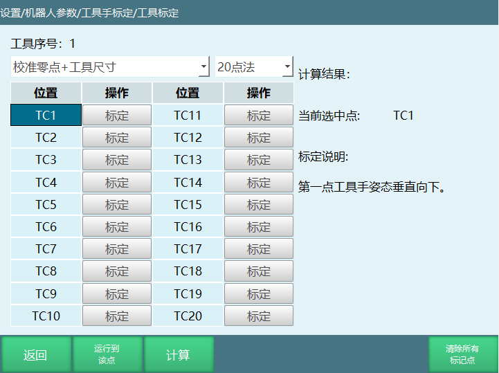
Specific calibration steps are as follows:
Find a reference point (pen tip as reference point), and ensure this reference point is fixed;
Start inserting position points, for each point inserted, click [Mark This Point], insert 20 points, the greater the attitude difference between each point, the better;
Manufacturer recommendation: Calibration steps, first point tool hand attitude vertical downward, second point move A+ axis, third point move A+, fourth point move A+, fifth point move A-, sixth point move A-, seventh point move A-, eighth point move B+, ninth point move B+, tenth point move B+, eleventh point move B-, twelfth point move B-, thirteenth point move B-, remaining points mainly move C axis in a cross pattern for calibration.
Specific calibration steps are as follows:
TCP1: First point robot, robot tool hand end vertical reference point;
TCP2: Second point robot, robot moves A+ based on the first point;
TCP3: Third point robot, robot moves A+ 40 degrees based on the first point;
TCP4: Fourth point robot, robot moves A+ 60 degrees based on the first point;
TCP5: Fifth point robot, robot moves A- 20 degrees based on the first point;
TCP6: Sixth point robot, robot moves A- 40 degrees based on the first point;
TCP7: Seventh point robot, robot moves A- 60 degrees based on the first point;
TCP8: Eighth point robot, robot moves B+ 20 degrees based on the first point;
TCP9: Ninth point robot, robot moves B+ 30 degrees based on the first point;
TCP10: Tenth point robot, robot moves B+ 40 degrees based on the first point;
TCP11: Eleventh point robot, robot moves B- 20 degrees based on the first point;
TCP12: Twelfth point robot, robot moves B- 30 degrees based on the first point;
TCP13: Thirteenth point robot, robot moves B- 40 degrees based on the first point;
TCP14: Fourteenth point robot, robot moves C+ 30 degrees based on the first point;
TCP15: Fifteenth point robot, robot moves C+ 50 degrees based on the first point;
TCP16: Sixteenth point robot, robot moves C+ 70 degrees based on the first point;
TCP17: Seventeenth point robot, robot moves C+ 90 degrees based on the first point;
TCP18: Eighteenth point robot, robot moves C- 30 degrees based on the first point;
TCP19: Nineteenth point robot, robot moves C- 60 degrees based on the first point;
TCP20: Twentieth point robot, robot moves C- 90 degrees based on the first point.
[Calculate]: After calibration is complete, click calculate to calculate the calibration result. If the calculated value is large, recalibration is needed.
[Cancel Calibration]: If you are not satisfied with a certain point after calibration, you can click the [Cancel Calibration] button corresponding to that row, cancel the calibration and calibrate that point again.
[Run to This Point]: After each point is calibrated, you can click [Run to This Point], the robot will run to that point.
[Mark Result Position as Zero Point]: Set the calibration compensation position as the current robot's zero point position.
[Clear All Calibration Points]: Calibration points will be saved to the controller, the calibration results will only be cleared after clicking cancel calibration, clearing all calibration points, or switching tool hand to enter calibration interface.
Click "Tool Calibration", select the button for Calibrate Tool Size + Attitude - 20-point method to enter the "Twenty-Point Calibration" interface without zero point calibration, as shown in the figure:
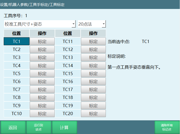
Specific calibration steps are as follows:
TCP1: First point robot, robot tool hand end vertical reference point;
TCP2: Second point robot, robot moves A+ based on the first point;
TCP3: Third point robot, robot moves A+ 40 degrees based on the first point;
TCP4: Fourth point robot, robot moves A+ 60 degrees based on the first point;
TCP5: Fifth point robot, robot moves A- 20 degrees based on the first point;
TCP6: Sixth point robot, robot moves A- 40 degrees based on the first point;
TCP7: Seventh point robot, robot moves A- 60 degrees based on the first point;
TCP8: Eighth point robot, robot moves B+ 20 degrees based on the first point;
TCP9: Ninth point robot, robot moves B+ 30 degrees based on the first point;
TCP10: Tenth point robot, robot moves B+ 40 degrees based on the first point;
TCP11: Eleventh point robot, robot moves B- 20 degrees based on the first point;
TCP12: Twelfth point robot, robot moves B- 30 degrees based on the first point;
TCP13: Thirteenth point robot, robot moves B- 40 degrees based on the first point;
TCP14: Fourteenth point robot, robot moves C+ 30 degrees based on the first point;
TCP15: Fifteenth point robot, robot moves C+ 50 degrees based on the first point;
TCP16: Sixteenth point robot, robot moves C+ 70 degrees based on the first point;
TCP17: Seventeenth point robot, robot moves C+ 90 degrees based on the first point;
TCP18: Eighteenth point robot, robot moves C- 30 degrees based on the first point;
TCP19: Nineteenth point robot, robot moves x- based on the first point;
TCP20: Twentieth point robot, robot moves y+ based on the first point.
[Calculate]: After calibration is complete, click calculate to calculate the calibration result. If the calculated value is large, recalibration is needed.
[Cancel Calibration]: If you are not satisfied with a certain point after calibration, you can click the [Cancel Calibration] button corresponding to that row, cancel the calibration and calibrate that point again.
[Run to This Point]: After each point is calibrated, you can click [Run to This Point], the robot will run to that point.
[Clear All Calibration Points]: Calibration points will be saved to the controller, the calibration results will only be cleared after clicking cancel calibration, clearing all calibration points, or switching tool hand to enter calibration interface.
20 points without zero point calibration, calibrate size + attitude; run to calculation result position is always grayed out, calculation results can be saved.
| ⚠️ Notes |
|---|
| For the attitude of each point, please try to take arbitrary direction attitudes. If the attitude rotates along a fixed direction, it may cause inaccurate accuracy. |
| During the calibration process, please keep the reference point fixed, otherwise it will increase calibration error. |
How to Verify Calibration Accuracy
In teach mode, align the tool hand calibration tip with the calibration cone, when the two tips are aligned, select the calibrated tool hand number, then jog the A, B, C axes under Cartesian coordinate system, and check if the tips are aligned and how many mm they are offset.
Q&A
Q: What is the tool coordinate system?
A: The tool coordinate system is the coordinate system of the robot end tool, the origin is TCP (tool center point), used to determine the tool's pose.
Q: Why establish a tool coordinate system?
A: 1. Establish the tool's TCP point for easy tool state adjustment; 2. Determine the tool feed direction for easy tool position adjustment.
Q: When is tool hand calibration needed?
A: When rotation around X, Y, Z attitude axes is needed, tool hand calibration is required, such as welding process, polishing process, spraying process, etc.
Q: When is tool hand not needed?
A: When the robot itself only performs Z-axis attitude rotation, and the tool tip is located on the center extension line of the robot's 6th axis flange; at this time, tool hand parameters do not need to be set.
Q: How to choose the tool hand calibration method?
A: 1. Has done laser calibration + using welding torch: use 6-point calibration; 2. Has not done laser calibration + using welding torch: use 12-point calibration; 3. Calibrating palletizing gripper: prioritize directly filling in tool dimensions; 4. Zero point lost: use 20-point calibration; 5. After 6-point calibration, A, B axis rotation error is large: use 7-point calibration.
Q: How to directly fill in gripper dimensions?
A: Prepare the gripper length, width, and height parameters, fill the gripper tip offset on X, Y, Z axes into the corresponding offset fields, note that X axis positive direction is positive value, Y, Z axis positive direction is negative value.
Q: What are the steps for 6-point calibration?
A: 1. TC1: Robot 5th axis vertical downward; 2. TC2: Based on the first point, rotate C axis 180°; 3. TC3: Based on the first point, B axis angle at 35°; 4. TC4: Robot returns to zero point, tool hand tip vertical; 5. TC5: Based on the fourth point, move X-; 6. TC6: Based on the fifth point, move Y+; finally click calculate.
Q: How to verify calibration accuracy?
A: In teach mode, align the tool hand calibration tip with the calibration cone, when the tips are aligned, select the calibrated tool hand parameters, switch the jog coordinate system to Cartesian, jog the A, B, C axes, and check if the tips are aligned and how many mm they are offset.