Interference Zone
The interference zone adds a tool cube function, which extends the interference zone determination from the tool tip to a rectangular volume.
Before use, the interference zone must be calibrated. The calibration method is the same as the original interference zone method.
Tool Cube
- A new interference zone tab and tool control point / tool cube selection checkbox are added to the tool calibration interface.
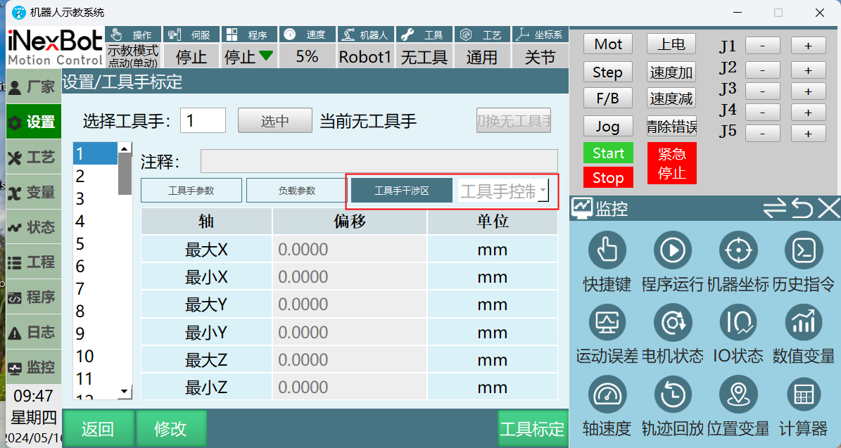
- Selecting "Tool Control Point" is consistent with the original interference zone function. Selecting "Interference Zone Cube" requires setting the cube dimensions.
The maximum direction value must not be less than the minimum direction value, and vice versa.
Max X: Tool control point X positive direction offset
Min X: Tool control point X negative direction offset
Max Y: Tool control point Y positive direction offset
Min Y: Tool control point Y negative direction offset
Max Z: Tool control point Z positive direction offset
Min Z: Tool control point Z negative direction offset
- When the interference zone cube is selected and the interference zone has been calibrated, any position within the tool cube volume can trigger the interference zone.
Not just the 8 corner points, but also every edge and face.
AI Retrieval Q&A Pairs
Q: What are the rules for cube parameters?
A: The maximum direction value for each axis must not be less than the minimum direction value. Set the X, Y, Z positive and negative direction offsets separately.
Q: Which parts of the cube can trigger interference?
A: Any position within the cube, including faces, edges, interior, and all 8 corner points, will trigger when entering the interference zone.