Modbus Function User Tutorial
Modbus Instructions
MODBUS_OPEN --- Open MODBUS Connection
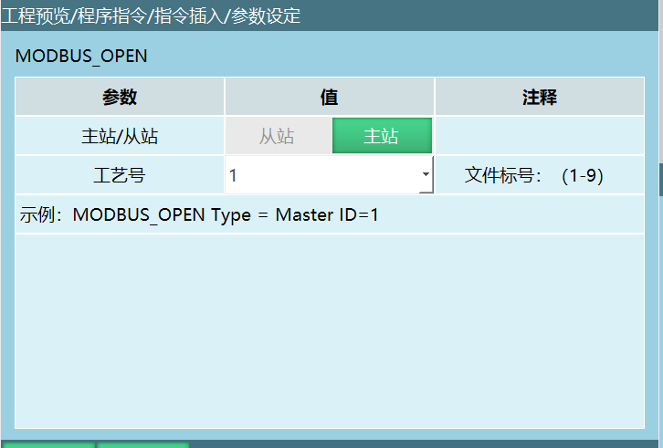 Format: MODBUS_OPEN [Instruction Name] Type=Master, Slave [Master/Slave] ID [Process Number].
Function: Open a Modbus communication connection.
Parameters:
| Master/Slave | Select Master: execute the open MODBUS connection instruction, MODBUS master connection succeeds. Select Slave: execute the open MODBUS connection instruction, MODBUS slave connection succeeds. |
|---|---|
| Process Number | When Slave is selected, the process number cannot be modified. When Master is selected, the process number supports 1–9. |
MODBUS_CLOSE --- Disconnect MODBUS Connection
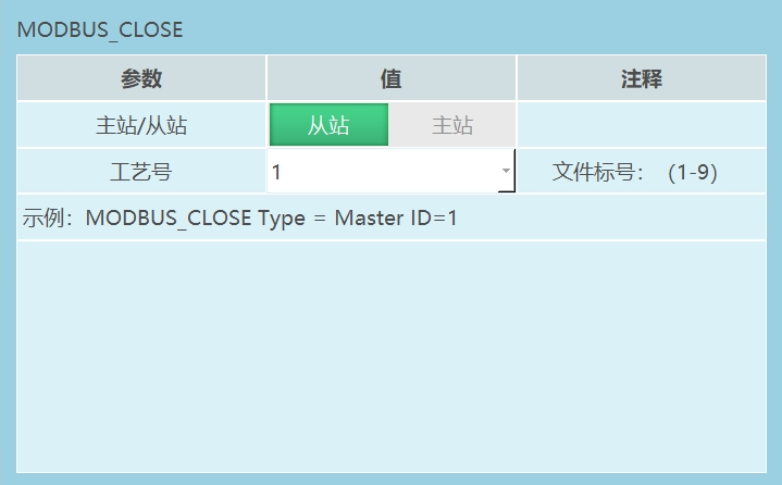 Format: MODBUS_CLOSE [Instruction Name] Type=Master, Slave [Master/Slave] ID [Process Number].
Function: Disconnect the Modbus communication connection.
Parameters:
| Master/Slave | Select Master: execute the MODBUS disconnect instruction, MODBUS master communication disconnects. Select Slave: execute the MODBUS disconnect instruction, MODBUS slave communication disconnects. |
|---|---|
| Process Number | When Slave is selected, there is no process number. When Master is selected, the process number supports 1–9. |
MODBUS_CONNECTION_STATUS --- Get MODBUS Connection Status
Format: MODBUS_CONNECTION_STATUS [Instruction Name] Type=Master, Slave [Master/Slave] ID [Process Number] B/GB [Variable to Store Status].
Function: Store the Modbus communication connection status into a variable. If the connection succeeds, the variable value is set to 1; if the connection fails, the variable value is set to 0.
Parameters:
| Master/Slave | Select Master: execute the instruction to get the master connection status. Select Slave: execute the instruction to get the slave connection status. |
|---|---|
| Process Number | When Slave is selected, there is no process number. When Master is selected, the process number supports 1–9. |
| Status Storage Variable | Store the obtained status into the variable. Example: Modbus slave connection, selected variable is GB001. First execute the open Modbus connection instruction, then execute the get Modbus connection instruction. If the Modbus slave connection succeeds, GB001=1; if the connection fails, GB001=0. |
MODBUS_READ --- MODBUS Read Instruction
Format: MODBUS_READ [Instruction Name] ID [Process Number] 4X / 3X / 4X-bit / 3X-bit / 0X / 1X [Address Type] 5 [Slave Register Start Address] 1 [Number of Slave Addresses to Read] B001 [First Data Storage Variable].
Function: Read the value at the corresponding address in Modbus.
Parameters:
Process Number: Range [1,9]. The process number selected in the instruction must match the process number selected in the Modbus parameter interface.
Address Type:
- 3X: Read the value at the corresponding address in Modbus.
- 4X: Same as 3X.
- 3X-bit: Read the status of any bit of the value stored at the selected address.
- 4X-bit: Same as 3X-bit.
- 0X: Readable and writable device type, equivalent to operating PLC output points.
- 1X: Read-only device type, equivalent to operating PLC input points.
- Data Type: When the first data storage variable is I or GI, the slave data type can be short or ushort (corresponding to short integer and unsigned short integer, with ranges [-32768, 32767] and [0, 65535] respectively).
Note: When the first data storage variable is I or GI, the data type must match the slave data type, otherwise data errors may occur.
Slave Register Start Address: Read parameter values starting from the address set in the instruction parameters. If the start address is set to 5, the read instruction will start reading from Modbus address 5.
Number of Slave Addresses to Read: The number of addresses to read. If set to 3, the read instruction will read 3 addresses starting from the start address (including the start address, 3 addresses total).
First Data Storage Variable: Store the read parameters into variables. If the first variable is I001 and the number of addresses to read is 3, the read instruction will store the parameter values into I001, I002, I003 sequentially.
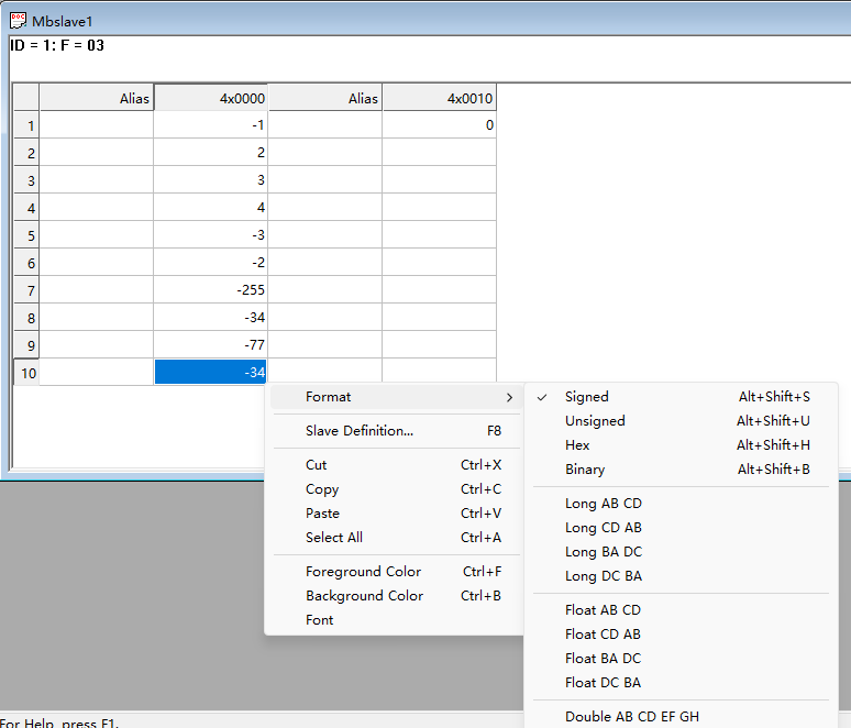
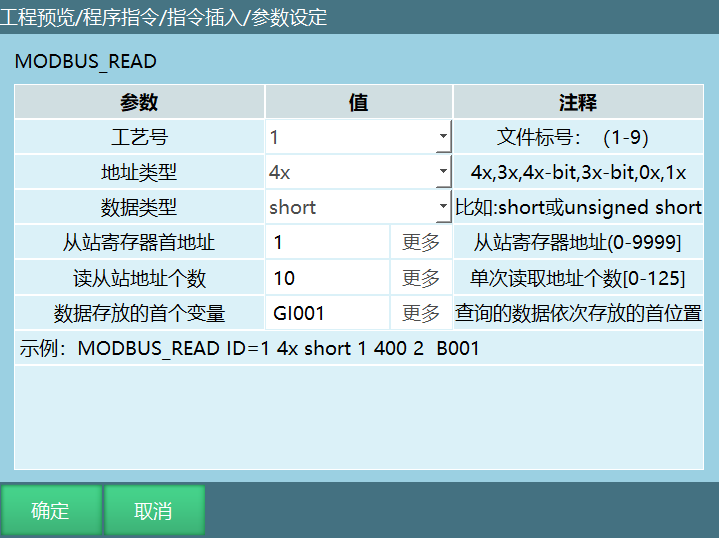
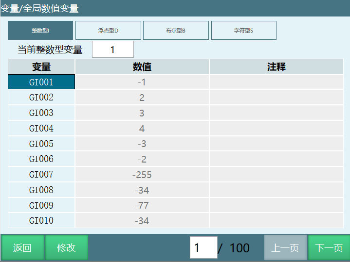
Example 1: Address type 4X, first data storage variable GI001, slave start address 1, number of slave addresses to read 10.
Example: Execute the Modbus read instruction as shown below, reading the values of Modbus addresses 1–10 into variables GI001–GI010.
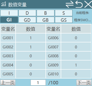
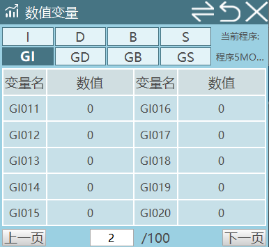
Example 2: Address type 3X-bit, first data storage variable GI001, slave start address 1, number of slave addresses to read 16.
Example: The value stored at Modbus address 1 is 259, represented in 16-bit binary as 0000 0001 0000 0011. Store the 16-bit value sequentially into 16 variables (starting from the selected first variable, storing the 16-bit raw code from right to left).
First data storage variable is GI001, so convert 259 to binary and store each bit from right to left into GI001–GI016.
Example 3: Address type 3X-bit, first data storage variable I001, slave start address 1, number of slave addresses to read 8.
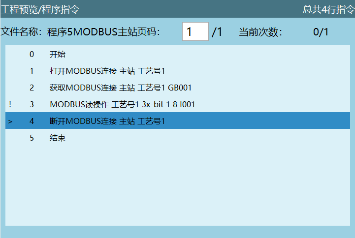
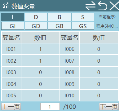
The value stored at Modbus address 1 is 259, represented in 16-bit binary as 0000 0001 0000 0011. Since the number of slave addresses to read is 8, execute the Modbus read instruction to store 8 values sequentially (from the selected first variable, right to left).
First data storage variable is I001, so convert 259 to binary and store the 8 read values (0000 0011) into I001–I008.
Notes:
When address type is 3X-bit, the range of slave addresses is [0,16].
When address type is 3X-bit, the 17th bit when storing to a variable is the sign bit, where 0 indicates positive and 1 indicates negative.
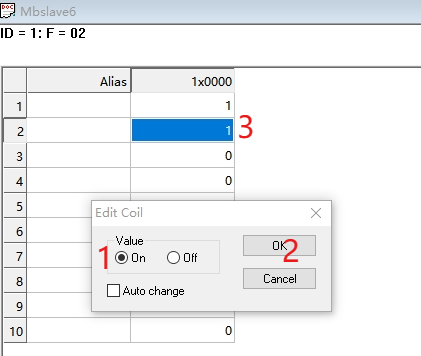
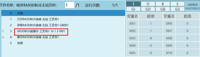
Example 4: Address type 1X, first data storage variable I001, slave start address 1, number of slave addresses to read 1.
Example: As shown below, 0X and 1X only have "0" and "1" states. When Value is On, it represents 1; when Off, it represents 0. After executing the Modbus read instruction, the status of the corresponding address is stored into the variable.
Example 5: Address type 3X, first data storage variable S001, slave start address 1, number of slave addresses to read 5.
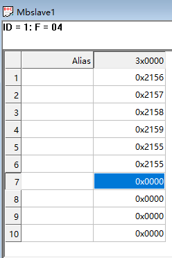
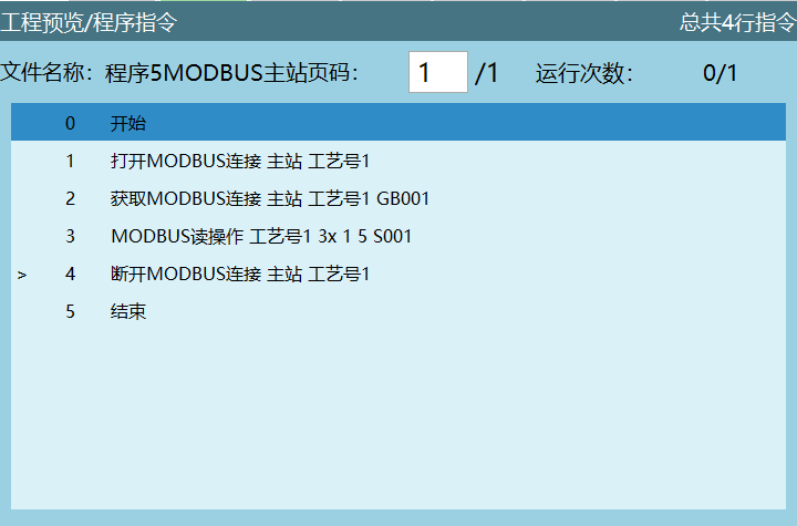
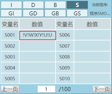
Execution result: After executing the instruction, the read values of master addresses 1–5 are stored into variable S001. Addresses exceeding the read count cannot be read.
Notes:
- When reading character type, all read values are stored into a single variable. Unlike integer, float, and boolean types, they are not stored sequentially into other variables based on the start address and read count.
Example: If the first variable is S001, all read values will be stored into S001.
When selecting character type variables, change the address Format to hexadecimal Hex.
Two hexadecimal numbers represent one ASCII character. For example, 0X2156: 21 represents one character, 56 represents one character. Refer to the ASCII table for the specific characters read.
Example 6: Address type 3X, first data storage variable D001, slave start address 1, number of slave addresses to read 10.
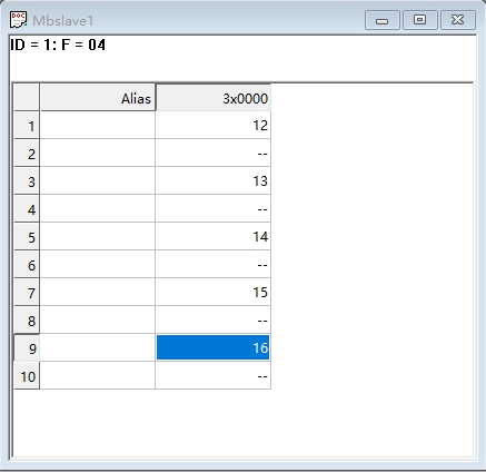
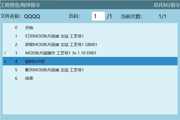
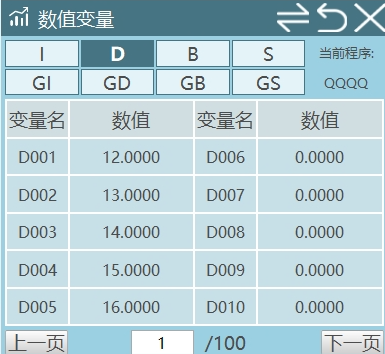
Execution result: Execute the Modbus read instruction to store the read floating-point numbers into D001–D005.
Note: Since 2 register addresses represent one floating-point number, the "number of slave addresses to read" should be an even number, and the correct endianness mode must be set when reading floating-point variables.
Floating-Point Endianness Swap Settings
Modbus Settings - Modbus Parameters. Both the slave and master interfaces add endianness swap settings for reading and writing floating-point numbers, as shown below:
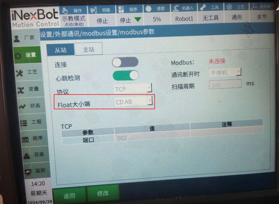
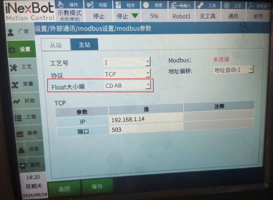
The Float endianness options are: AB CD, CD AB, BA DC, DC BA.
Endianness Mode Explanation:
- AB CD: Data is stored in big-endian mode, high byte first.
- CD AB: Data is stored in little-endian mode, low byte first.
- BA DC: Also big-endian mode, but with the order of high and low bytes reversed.
- DC BA: Also little-endian mode, but with the order of high and low bytes reversed.
Example:
If the teach pendant selects CD AB mode, this means data is stored in little-endian mode. In this case, to ensure correct data transmission and parsing, Modbus Poll software must also be set to the same Float CD AB format for reading, writing, and modifying the corresponding addresses.
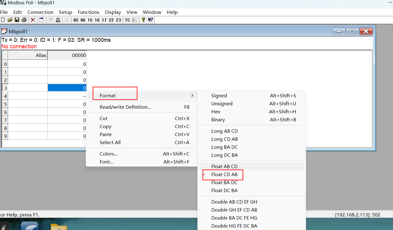
Notes:
- When setting the endianness mode, ensure that the sender and receiver are consistent, otherwise data parsing errors will occur.
MODBUS_WRITE --- MODBUS Write Instruction
Format: MODBUS_WRITE [Instruction Name] ID [Process Number] 4X / 4X-bit / 0X [Address Type] B001 [First Data Storage Variable] 1 [Slave Register Start Address] 5 [Number of Slave Addresses to Write].
Function: This instruction is used to write variables into the corresponding addresses of the slave register via Modbus.
Parameters:
Process Number: Range [1,9]. The process number selected in the instruction must match the process number selected in the Modbus parameter interface.
Address Type:
- 4X: Write the values from variables into the address codes.
- 4X-bit: Compose variables into 16-bit binary codes and write into the address codes.
- 0X: Write variable values into address codes, with only "0" and "1" states. If a variable has a value, write 1; if no value, write 0.
First Data Storage Variable: The type of variable to write.
Slave Register Start Address: The first address to start writing. If the start address is 5, the write instruction will start writing from Modbus address 5.
Number of Slave Addresses to Write: The number of addresses to write. If set to 3, it means writing to 3 addresses starting from the start address (including the start address).
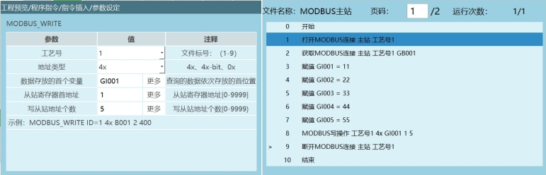
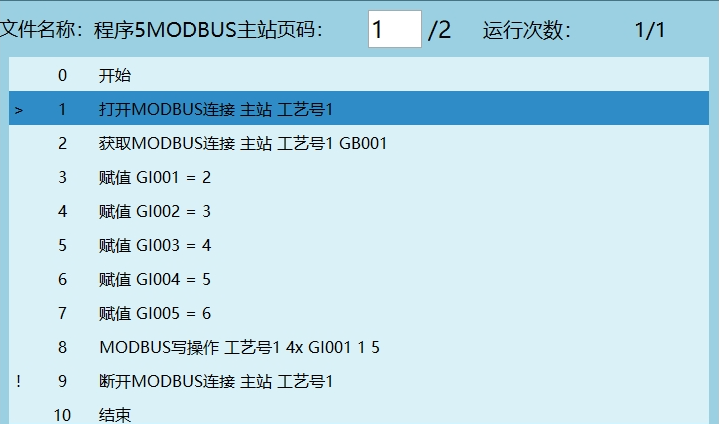
Example 1: Address type 4X, first data storage variable GI001, slave start address 1, number of slave addresses to write 5.
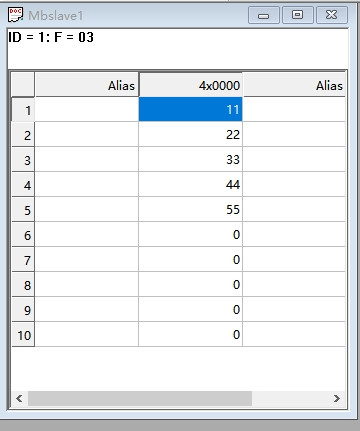
Execute the Modbus write instruction to write the values of the assigned variables into the corresponding Modbus address codes — GI001's value into Modbus address 1, GI002's value into Modbus address 2, and so on until Modbus address 5 is written.
Note: When the MODBUS_WRITE instruction "first data storage variable" is set.
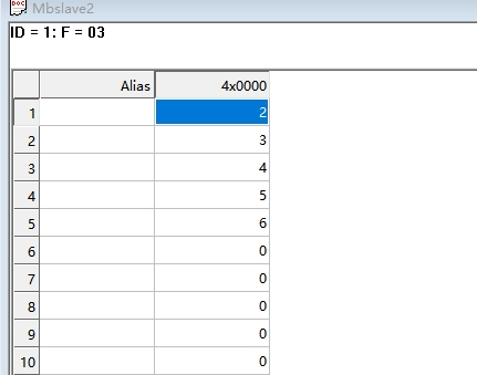
Example 2: Address type 4X-bit, first data storage variable I001, slave start address 1, number of slave addresses to write 10.
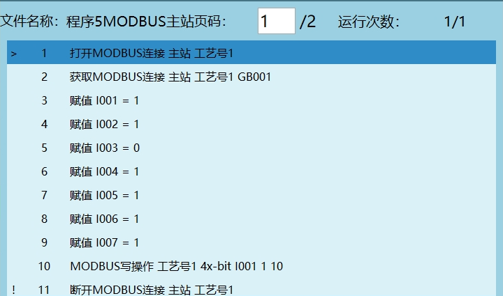
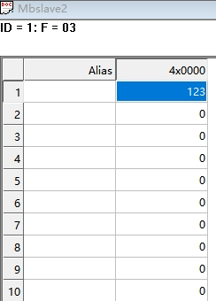
As shown below, I001=1 corresponds to address 1, I002=2 corresponds to address 2, I003=0 corresponds to address 3, I004=4 corresponds to address 4, I005=5 corresponds to address 5, I006=6 corresponds to address 6, I007=1 corresponds to address 7. I008, I009, I010 correspond to addresses 8, 9, 10 respectively. Since I008, I009, I010 are not assigned, they default to 0.
Therefore, the values assigned to I001–I010 in binary (left to right) are 00 0111 1011, which converts to decimal 123.
Notes:
When address type is 4X-bit, the range of addresses is [0,16].
When address type is 4X-bit, the 17th bit when storing to a variable is the sign bit, where 0 indicates positive and 1 indicates negative.
Example 3: Address type 4X, first data storage variable GS001, slave start address 1, number of slave addresses to write 5.
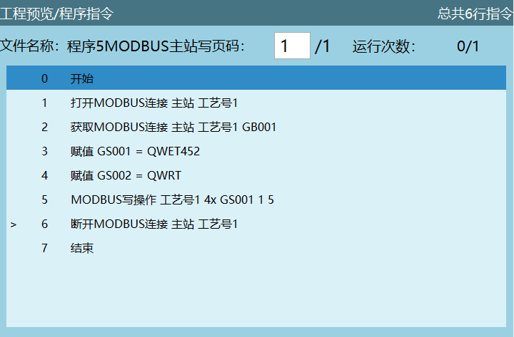
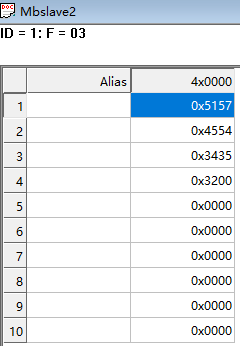
Execution result: Execute the Modbus write instruction to write the value of character variable GS001 into the address.
Note: Character variables can only be written to one address and will not extend to subsequent addresses.
Example: If the first variable is GS001 and the write count is 5, and variables GS001, GS002, GS003, GS004, GS005 are all assigned values in the program, the Modbus write instruction will only write the value of GS001 into the address. The values of GS002–GS005 cannot be written.
Change the address Format to hexadecimal Hex.
One address code corresponds to two characters, and one character corresponds to two hexadecimal digits.
Example: As shown above, GS001=QWET452. Q in hex is 51, W in hex is 57. Characters QW in hex are written to address 1, ET to address 2, 45 to address 3, and the first digit of 2 to address 4. Refer to the ASCII table to verify if the written values are correct.
Modbus Slave
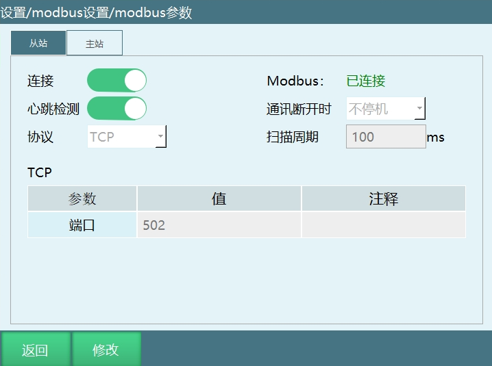
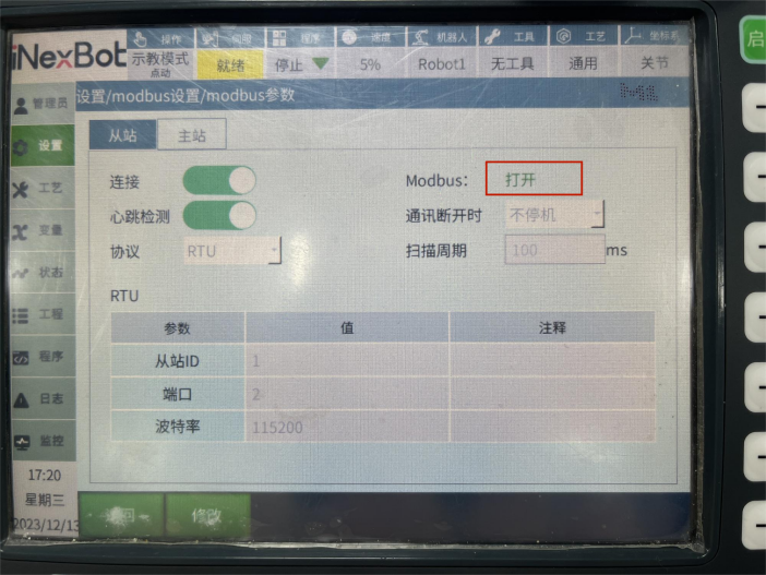
Connection: Open the connection enable switch to connect to Modbus. Without enabling, Modbus cannot connect successfully.
Modbus: Monitor the Modbus connection status.
Heartbeat Detection: When enabled, used to detect the send/receive frequency between Modbus and the controller. After disconnecting the Modbus connection, heartbeat detection shows data send/receive is closed.
When Communication Disconnects:
- Stop: When Modbus communication disconnects, the robot powers off.
- No Stop: When Modbus communication disconnects, the robot does not power off.
Protocol:
- RTU: Serial 232, 485 communication.
- TCP: TCP protocol.
Scan Period: The period at which the system scans data within the Modbus range.
The system default timeout is 500ms. If no data is received within 500ms, the connection is automatically disconnected.
Modbus Poll Slave Connection
TCP Protocol
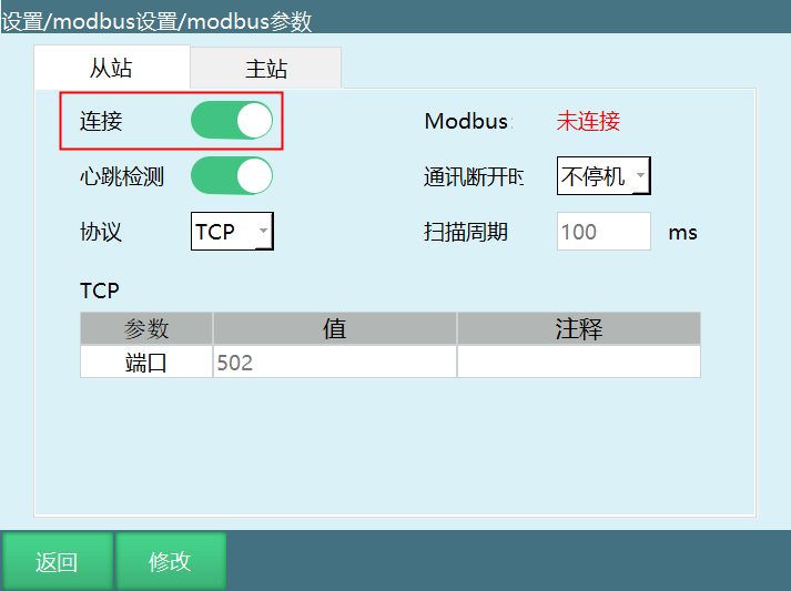
Click Settings - Modbus Settings - Modbus Parameters to enter the Modbus parameter interface, and open the connection switch.
Open the Modbus Poll software.
After opening the software, click Connection, select Connect to enter the Connection Setup interface.
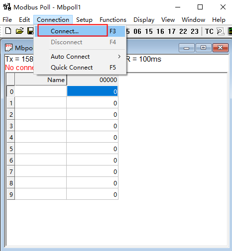
- Select Modbus TCP/IP for connection, and enter the IP Address of the currently connected controller.
Set the parameters (the parameters shown are for example only), and click OK.
Note: The IP address is the IP of the currently connected controller. When selecting the TCP protocol, the host IP subnet must match the controller IP subnet.
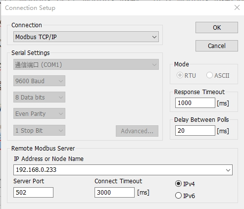
The teach pendant page shows "Connected". If the Modbus parameter interface shows connected and disconnected flashing, change the Scan Rate parameter in Setup — Read/Write Definition from 1000ms to 100ms.
After Modbus connection succeeds, the robot can be controlled via address codes.
Example 1: Modbus switch servo status;
4X type address code 29 write 2, servo stops;
4X type address code 29 write 1, servo ready.
Operation Method:
- Click Setup - Read/Write Definition.
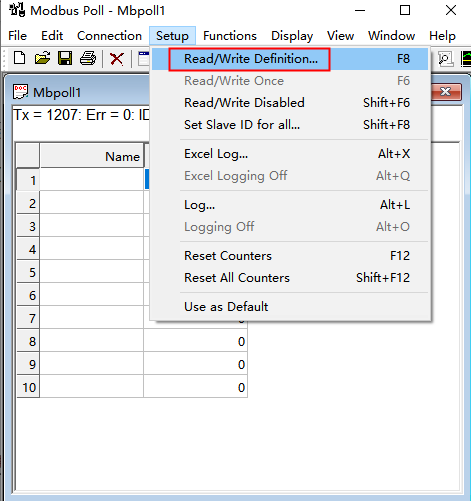
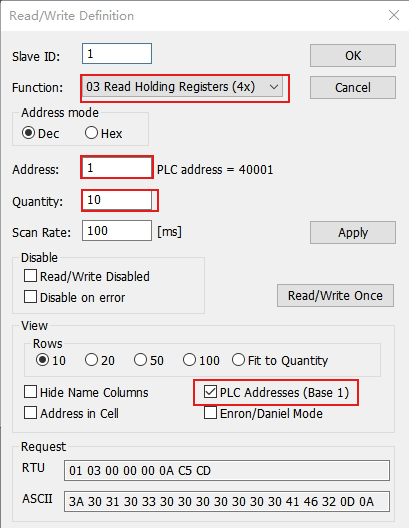
- Enter the Read/Write Definition interface, select address type 4X, set the start address Address, address count Quantity, check PLC Addresses (Base 1), and after setting the parameters, click OK to enter values in the corresponding address codes.
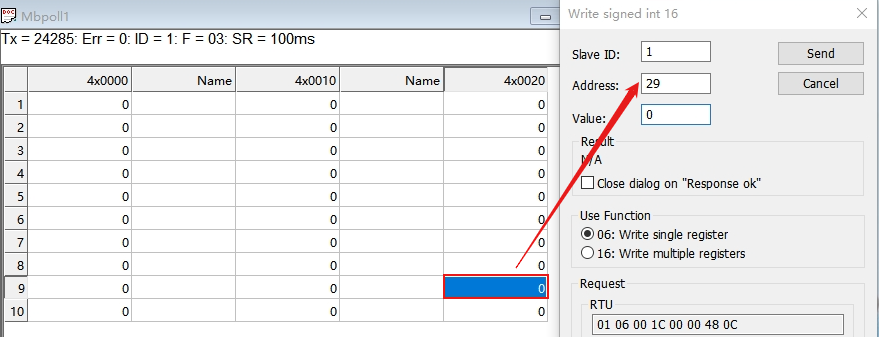
- Double-click the corresponding address and fill in the relevant address code:
Address code 29, Value write 1, servo status switches to ready;
Address code 29, Value write 2, servo status switches to servo stop.
RTU Protocol
232 Communication
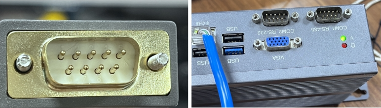
232 communication wiring:
Pin 2 of the 232 serial cable connects to pin 3 of the controller COM2_RS-232 port;
Pin 3 of the 232 serial cable connects to pin 2 of the controller COM2_RS-232 port;
Pin 5 of the 232 serial cable connects to pin 5 of the controller COM2_RS-232 port.
After wiring is complete, open the Modbus Poll software:
Click Connection, select Connect to enter the Connection Setup interface, as shown below:
- Select Serial Port for connection, select the detected serial port number in Serial Setting, set the parameters (the parameters shown are for example only), and click OK.
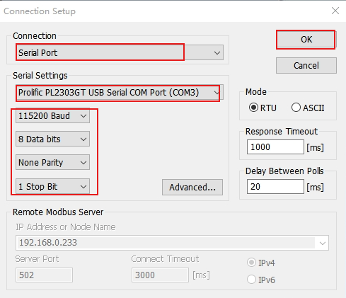
- Modbus connection succeeds.
- After Modbus connection succeeds, the robot can be controlled via address codes. The address codes for specific functions can be found in the "Modbus Address Code List".
485 Communication
485 communication wiring:
Pin 1 of the 485 serial cable connects to pin 2 of the controller COM1_RS-485 port;
Pin 2 of the 485 serial cable connects to pin 1 of the controller COM1_RS-485 port.
After wiring is complete, open the Modbus Poll software.
Click Connection, select Connect to enter the Connection Setup interface.
- Select Serial Port for connection, select the detected serial port number in Serial Setting, set the parameters (the parameters shown are for example only), and click OK.
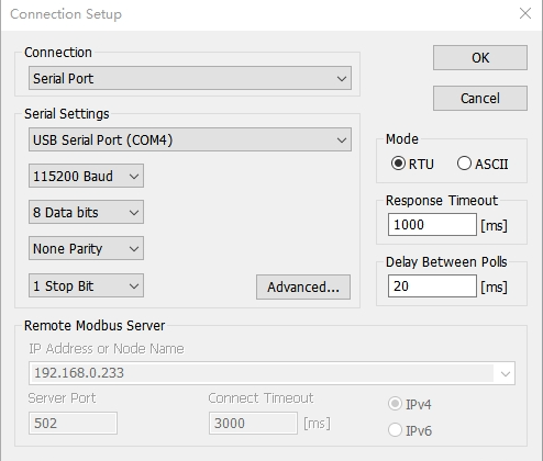
- Modbus connection succeeds.
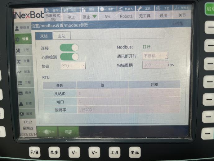
Note:
- When using 232 or 485 communication, ensure the port number is entered correctly.
Modbus Master
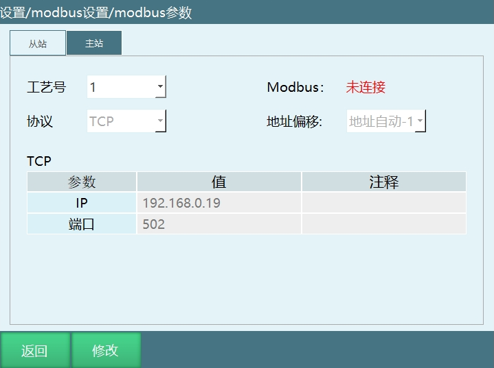
Process Number: The process number when connecting as master, supporting 1–9 process numbers.
Protocol: TCP, RTU (232, 485 communication).
Modbus: Monitor the Modbus master connection status.
Address Offset:
Address Auto -1: Start address is 1.
Address Unchanged: Start address is 0.
Modbus Slave Master Connection
TCP Protocol
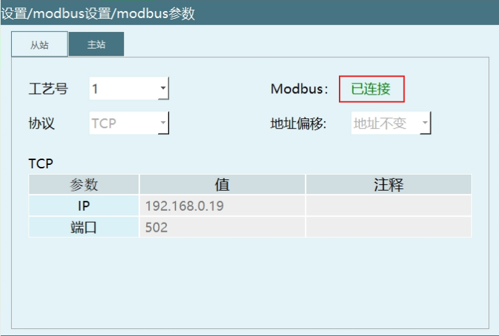
As shown below, the IP address during TCP communication is the current host address, not the currently connected controller IP.
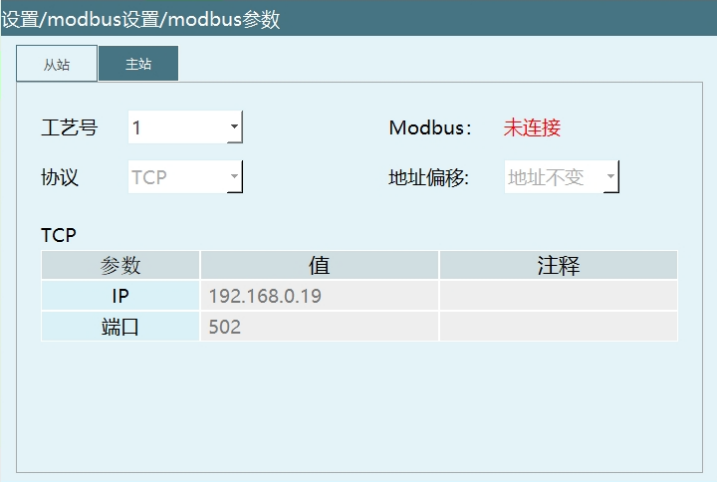
Set parameters in the Modbus master parameter interface.
Create a new project and insert a Modbus instruction.
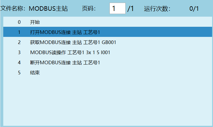
Open the Modbus Slave software.
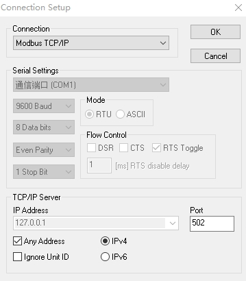
After opening the software, click Connection, select Connect to enter the Connection Setup interface.
- Select Modbus TCP/IP for Connection. The Port number must match the port number set in the Modbus parameter interface. Click OK.
- Execute the project interface from step 2 to open the MODBUS connection instruction. The Modbus master connection succeeds.
RTU Protocol
For 232 and 485 communication wiring methods, refer to the Modbus Poll slave connection section.
Modbus Master Read Parameters
Function: Read parameters from Modbus addresses into variables.
Example:
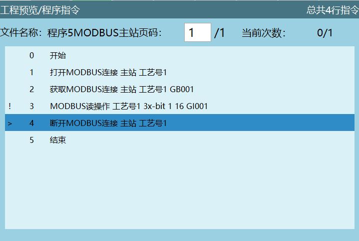
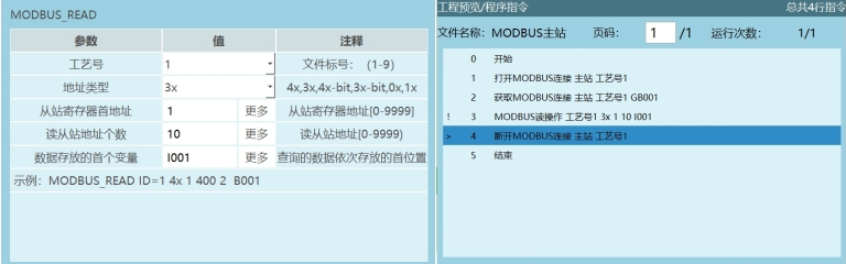
Open Modbus master communication;
If the Modbus master connection succeeds, variable GB001=1; otherwise GB001=0;
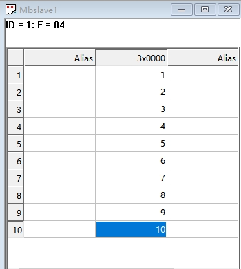
Execute the Modbus read instruction to read the values of the corresponding Modbus slave addresses into variables. First variable I001, read address count 10. After executing the instruction, the values of master addresses 1–10 are read into variables I001–I010;
Disconnect the Modbus master connection.
Modbus Master Write Parameters
Function: Write the assigned variable values into the corresponding addresses, as shown in the diagram below.