1 Process Introduction
The laser cutting process is divided into two parts: piercing and cutting. The cutting process performs piercing first. The piercing-related parameters and cutting mode parameters are set in the global variables, and parameters such as cutting gas pressure and power are set in the cutting variables. There is no physical difference between cutting and piercing; the distinction is only made to better achieve the cutting effect. Piercing is used to ensure that the material is fully penetrated at non-edge positions of the material, avoiding the situation where the material is not completely cut, and to reduce laser efficiency during the subsequent cutting process, thereby achieving the goal of energy saving.
During the cutting process, gas is continuously blown. This serves two purposes: first, to blow away the residue generated during cutting, ensuring a smooth and beautiful cut surface; second, to improve cutting efficiency — the oxygen concentration of the blown gas affects cutting efficiency. Within a safe range, the higher the concentration, the higher the cutting efficiency.
In combination with offline programming, complex trajectory cutting can be achieved.
2 Global Parameter Description
Open the teach pendant, enter the "Process" screen, select "Laser Cutting Process", and enter the "Global Parameters" screen.
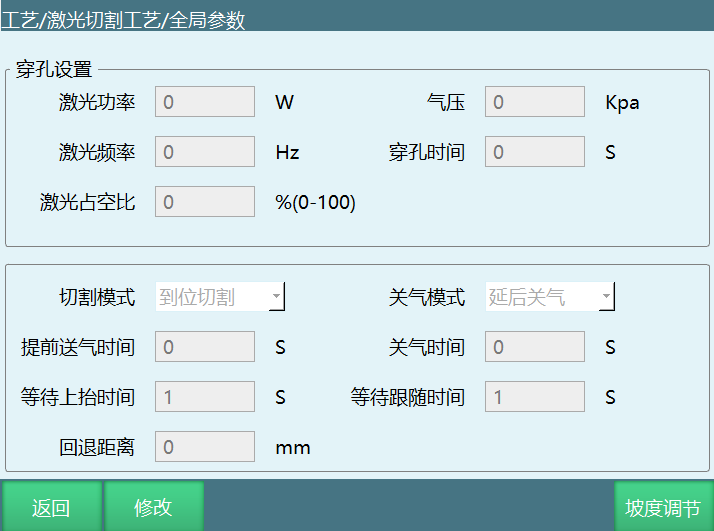
Piercing settings:
Laser power: The laser power during piercing, in W. The higher the power, the higher the piercing efficiency, but it also makes the cut surface rougher.
Gas pressure: The gas pressure output. The gas pressure control cleans the residue on the back side of the cut to ensure a smooth and clean cut surface.
Laser frequency: The number of times the laser emits per second.
Piercing time: The duration of piercing after the laser starts. The duration must ensure the current workpiece is fully penetrated.
Laser duty cycle: The proportion of time the laser works per unit time. For example, 66% means the laser works 0.66 s per second.
Cutting modes:
Cut on arrival: Run the cutting trajectory after piercing is completed.
Direct cut: Do not pierce; run the cutting trajectory directly.
Gas-off modes:
Delayed gas off: Delay the gas blow-off for a period of time after laser cutting ends.
Early gas off: Turn off the gas a period of time before laser cutting ends.
Gas-off time: The gas-off time that is advanced or delayed according to the set gas-off mode.
Early gas-on time: How long before laser cutting starts the gas is turned on in advance.
Wait-to-raise time: How long to wait before raising after laser cutting is completed.
Wait-for-follow time: The maximum time to wait for the follow-in-position signal after the follow signal is sent.
Retract distance: The retract distance to continue running after laser cutting is interrupted.
Note: After receiving the follow-in-position signal, the robot immediately runs the cutting trajectory. If the follow-in-position signal is not received within this time, the system will report a laser cutting follow-in-position timeout error.
3 Cutting Parameters
Open the teach pendant, enter the "Process" screen, select "Laser Cutting Process", and enter the "Cutting Parameters" screen.
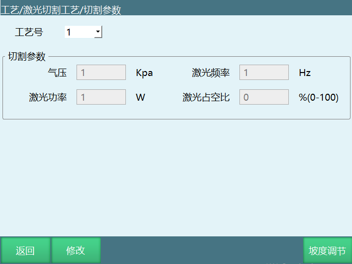
Process No.: Multiple sets of parameters can be saved and invoked in instructions.
Gas pressure: The gas pressure during cutting.
Laser power: The laser power during cutting.
Laser frequency: The number of times the laser emits per second.
Laser duty cycle: The proportion of time the laser works per unit time. For example, 66% means the laser works 0.66 s per second.
4 Analog Quantity Matching
Enter the "Process" screen, select "Laser Cutting Process", and enter the "Analog Quantity Matching" screen.
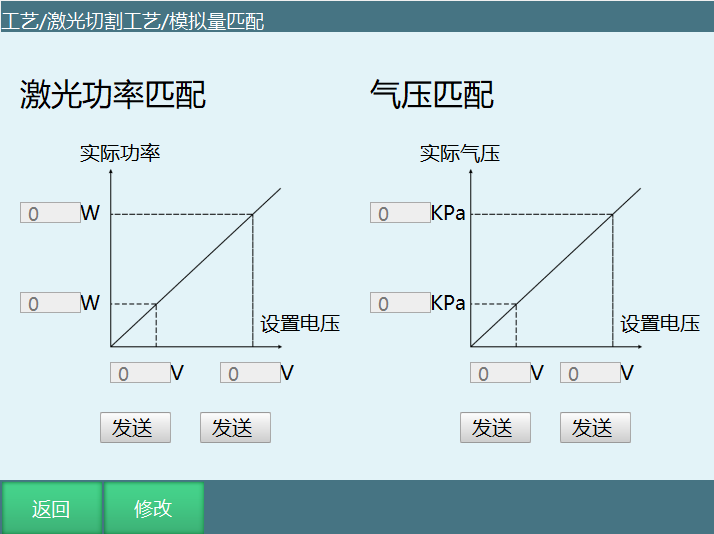
The usage is similar to welding current/voltage matching. The system calculates the proportional coefficient based on the filled-in set voltage value, the actual power value and the actual gas pressure value.
5 IO Settings
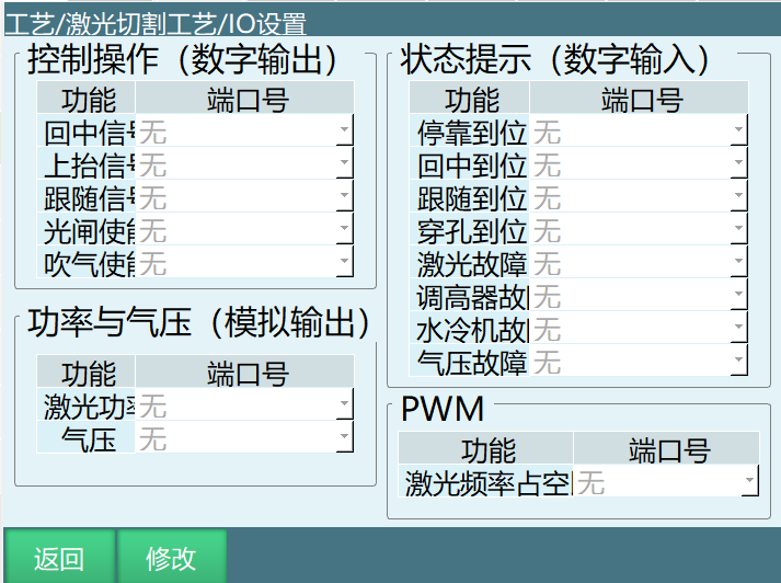
Divided into 4 parts: control operations, status prompts, power and gas pressure, and PWM.
5.1 Control Operations
Centering signal: After the corresponding signal is output, the laser is centered.
Raise signal: After the corresponding signal is output, the laser is raised.
Follow signal: After the corresponding signal is output, the laser starts following.
Light gate enable: After the corresponding signal is output, the light gate is opened.
Gas blow enable: After the corresponding signal is output, gas blowing starts.
5.2 Status Prompts
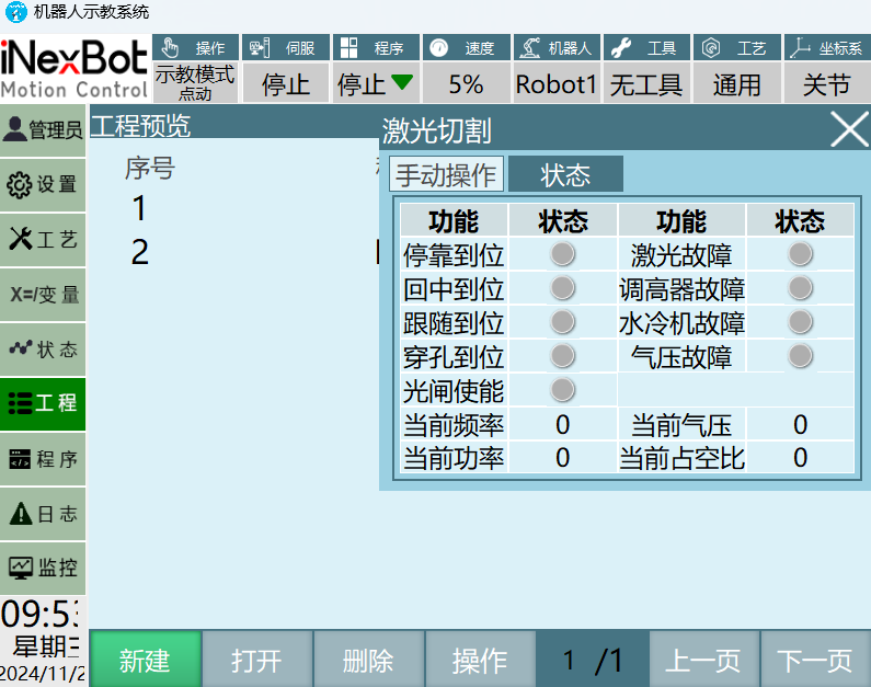
Parked in position: After the height controller stops and is in position, the corresponding port has an input signal.
Centered in position: After the height controller is centered and in position, the corresponding port has an input signal.
Followed in position: After the height controller follows and is in position, the corresponding port has an input signal.
Piercing complete: After laser cutting piercing is complete, the corresponding port has an input signal.
Laser fault: When a laser fault occurs, the corresponding port has an input signal and an error is reported to stop.
Height controller fault: When a height controller fault occurs, the corresponding port has an input signal and an error is reported to stop.
Chiller fault: When a chiller fault occurs, the corresponding port has an input signal and an error is reported to stop.
Gas pressure fault: When a gas pressure fault occurs, the corresponding port has an input signal and an error is reported to stop.
Note: Whether it is triggered can be viewed by clicking [Process] - [Cutting] - [Status] at the top of the system.
5.3 Power and Gas Pressure
Laser power: The analog port controlling laser power. The actual output is controlled according to the analog output.
Gas pressure: The analog port controlling gas pressure. The actual output is controlled according to the analog output.
5.4 PWM
Laser frequency duty cycle: Can be switched and set between two ports according to the R4PWMIO board. The port can only be selected if the PWMIO is present.
6 Manual Operation
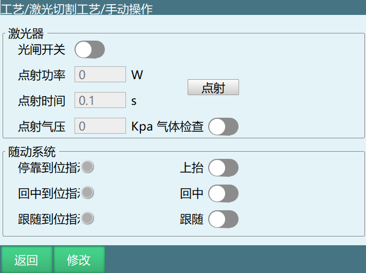
Enter the "Process" screen, select "Laser Cutting Process", and enter the "Manual Operation" screen.
6.1 Laser
Light gate switch: Similar to the welding enable. Only after it is turned on can the laser emit light. The light gate switch must be opened manually; it will not open automatically.
Spot power: The laser power during spot firing.
Spot time: The duration of a single spot firing.
Spot gas pressure: The gas pressure during spot firing.
Spot button: Used for debugging laser parameters. After setting the corresponding IO, clicking it emits light for convenient adjustment.
Gas check: Used for debugging laser parameters. After setting the corresponding IO, a gas pressure check can be performed for convenient adjustment.
6.2 Follow System
The three buttons, Raise, Center and Follow, control the laser respectively. They must be used after binding the IO. After arriving in position, the corresponding status indicator light on the left turns green.
7 Instruction Description
7.1 Laser On
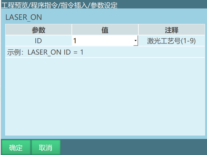
Example: LASER_ON【Instruction Name】ID=1【Process No.】.
Function: Start cutting after reaching the cutting start point.
Parameters: ID, laser cutting process number, range [1,9].
7.2 Laser Off
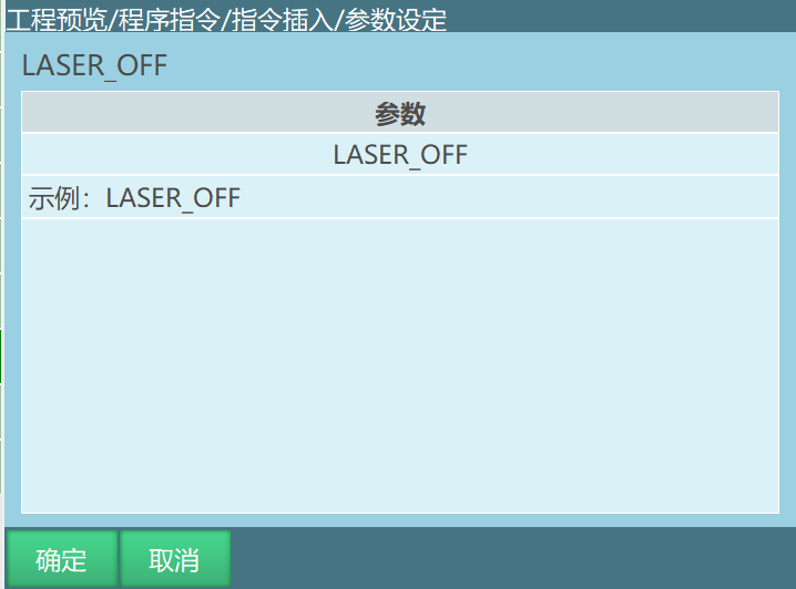
Function: Stop cutting after reaching the cutting end point.
Parameters: None.
7.3 Cutting Circle
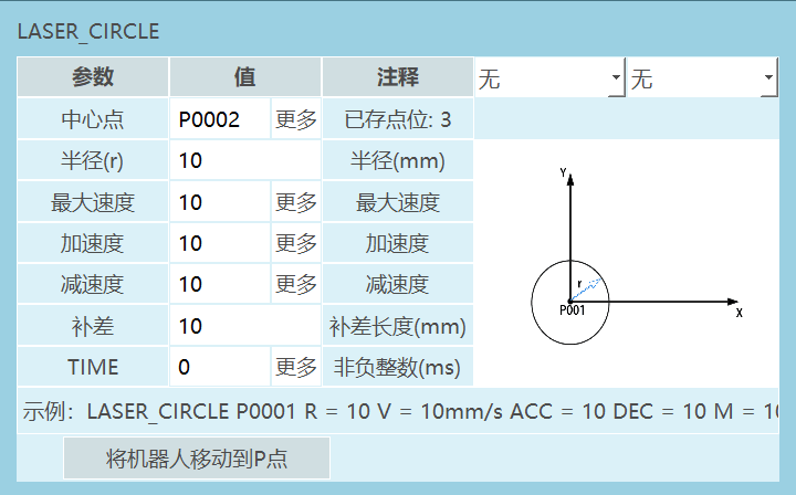
Example: LASER_CIRCLE【Instruction Name】 P/GP【Center Point】 R【Radius】 V【Maximum Speed】 ACC【Acceleration Ratio】 DEC【Deceleration Ratio】 M【Compensation】TIME 【Advance Execution Time, displayed as 0 if not set】.
Function: Set the cutting circle parameters. When running to this instruction, the cutting circle trajectory is run.
Parameters are shown in the table below:
    Center point                                The center point of the cutting circle trajectory. Use local position variable P or global position variable GP

   Radius (r)                                           Joint interpolation speed, range [1,3000]

   Maximum speed                                        The instruction speed during the cutting circle, range [1,999]

    Acceleration                                        The acceleration ratio during the cutting circle, range [1,100]

    Deceleration                                        The deceleration ratio during the cutting circle, range [1,100]

     Compensation                         After the full circle is completed, the distance to continue running the circle trajectory according to the compensation distance, range [0,500]

     TIME         Advance execution time, same as the advance execution time of motion control instructions. It is the time for the next non-motion instruction after this instruction to be executed in advance. Unit: ms
Example:
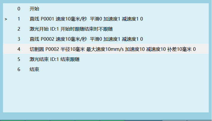
Laser instructions support straight lines, arcs, full circles and curves, and the usage is relatively simple. Only the cutting circle is special.
The cutting circle must be run based on the previous point. If the point of the previous motion instruction is P0001, the center point of the cutting circle must also be set to P0001 for it to run.
Q&A
Q1: What two phases does laser cutting include?
A: Piercing and cutting. Piercing ensures complete penetration of the material at non-edge positions, and then the cutting trajectory begins.
Q2: What is the purpose of gas blowing during cutting?
A: Two purposes: removing residue to obtain a smooth surface, and improving cutting efficiency through oxygen concentration.
Q3: What cutting modes are available?
A: Cut on arrival (piercing first) and direct cut (no piercing, run the trajectory directly).
Q4: What do the gas control modes include?
A: Two modes: delayed gas off and early gas off, both with configurable time parameters.
Q5: Which IO status signals are monitored?
A: Docking, centering, following and piercing signals, as well as fault signals of the laser, height controller, chiller and gas pressure.
Q6: How does the LASER_ON instruction work?
A: LASER_ON ID=n starts cutting at the current position using process number n (range 1-9).
Q7: What parameters does the LASER_CIRCLE instruction accept?
A: Center point, radius, maximum speed, acceleration/deceleration ratios, compensation distance, and an optional advance execution time.
Q8: What is the follow system?
A: The height controller, used to keep the distance between the laser head and the workpiece surface constant.
Q9: How does analog quantity matching work?
A: It calculates the scaling coefficient based on the set voltage and the actual power/pressure readings, enabling precise analog output control.
Q10: What safety functions are included?
A: Manual light gate enable, and fault monitoring of the laser, height controller, chiller and gas pressure.