Modbus Function User Manual
Modbus Instructions
MODBUS_OPEN - Open MODBUS Connection
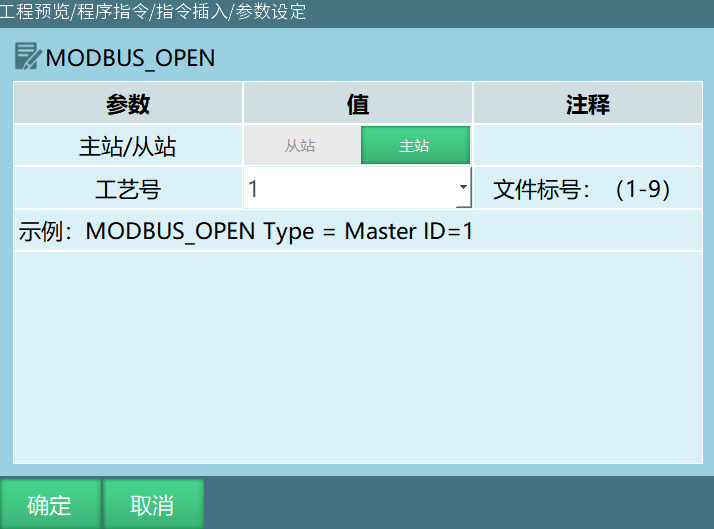
Format: MODBUS_OPEN [Instruction Name] Type=Master, Slave [Master, Slave] ID [Process Number].
Function: Open Modbus communication connection.
Parameters:
| Parameter | Description |
|---|---|
| Master/Slave | Select master, execute open MODBUS connection instruction, MODBUS master connection successful Select slave, execute open MODBUS connection instruction, MODBUS slave connection successful |
| Process Number | When selecting slave, process number cannot be modified. When selecting master, process number supports 1-9 |
MODBUS_CLOSE - Close MODBUS Connection
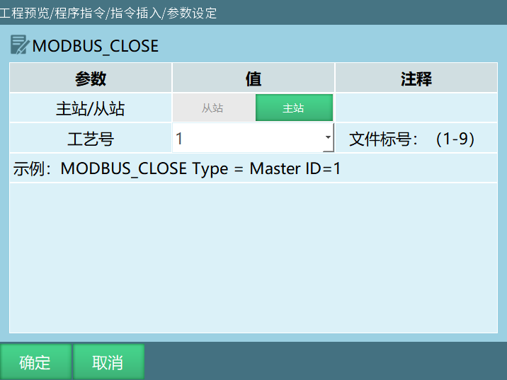
Format: MODBUS_CLOSE [Instruction Name] Type=Master, Slave [Master, Slave] ID [Process Number].
Function: Close Modbus communication connection.
Parameters:
| Parameter | Description |
|---|---|
| Master/Slave | Select master, execute MODBUS close instruction, MODBUS master communication disconnected Select slave, execute MODBUS close instruction, MODBUS slave communication disconnected |
| Process Number | When selecting slave, no process number. When selecting master, process number supports 1-9 |
MODBUS_CONNECTION_STATUS - Get MODBUS Connection Status
Format: MODBUS_CONNECTION_STATUS [Instruction Name] Type=Master, Slave [Master, Slave] ID [Process Number] B/GB [Variable to Store Status].
Function: Store the Modbus communication connection status into a variable. If connection is successful, the variable value is assigned 1. If connection fails, the selected variable is assigned 0.
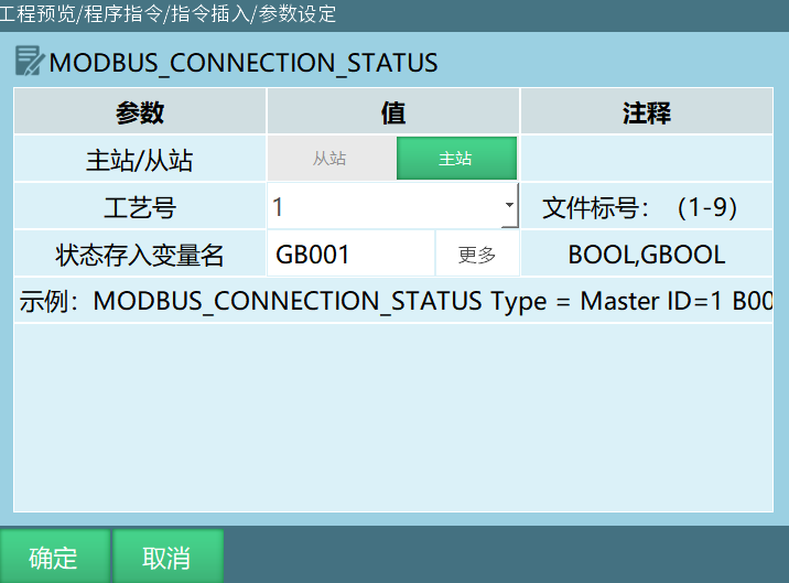
Parameters:
| Parameter | Description |
|---|---|
| Master/Slave | Select master, after executing the instruction, get the master's connection status Select slave, after executing the instruction, get the slave's connection status |
| Process Number | When selecting slave, no process number When selecting master, process number supports 1-9 |
| Variable to Store Status | Store the obtained status into a variable Example: Modbus slave connection, selected variable is GB001. First execute open Modbus connection instruction, then execute get Modbus connection instruction. If Modbus slave connection is successful, GB001=1. If connection fails, GB001=0 |
MODBUS_READ - MODBUS Read Instruction
Format: MODBUS_READ [Instruction Name] ID [Process Number] 4X /3X/ 4X-bit/ 3X-bit/ 0X/ 1X [Address Type] 5 [Slave Register Start Address] 1 [Read Slave Address Count] B001 [First Variable for Data Storage].
Function: Read the value at the corresponding address in Modbus.
Parameters:
| Parameter | Description |
|---|---|
| Process Number | Range [1,9]. The process number selected in the instruction must match the process number selected in the Modbus parameter interface |
| Address Type | 3X: Read the value at the corresponding address in Modbus 4X: Same as 3X 3X-bit: Read the status of any bit of the value stored at the selected address 4X-bit: Same as 3X-bit 0X: Readable and writable device type, equivalent to operating PLC output points 1X: Read-only device type, equivalent to operating PLC input points |
| Data Type | When the first variable for data storage is I or GI, the slave data type can be short and ushort (corresponding to short integer and unsigned short integer, the former range is [-32768,32767] and the latter range is [0,65535]) Note: When the first variable for data storage is I or GI, the data type must match the slave's data type, otherwise data errors may occur |
| Slave Register Start Address | Read the parameter value according to the start address set in the instruction parameters. If the start address set in the parameters is 5, after executing the read instruction, it will start reading from the 5th address of Modbus |
| Read Slave Address Count | Number of addresses to read. If the read slave address count is set to 3, after executing the read instruction, it will read 3 addresses from the start address (including the start address, total 3) |
| First Variable for Data Storage | Store the read parameters into variables. If the first selected variable is I001 and the read address count is 3, after executing the read instruction, the parameter values will be stored sequentially into I001, I002, I003 |
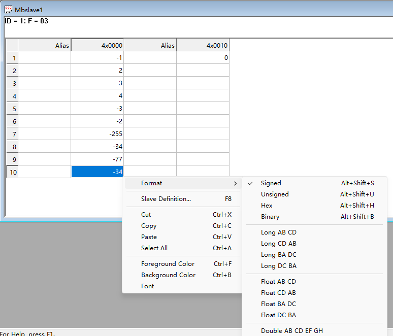
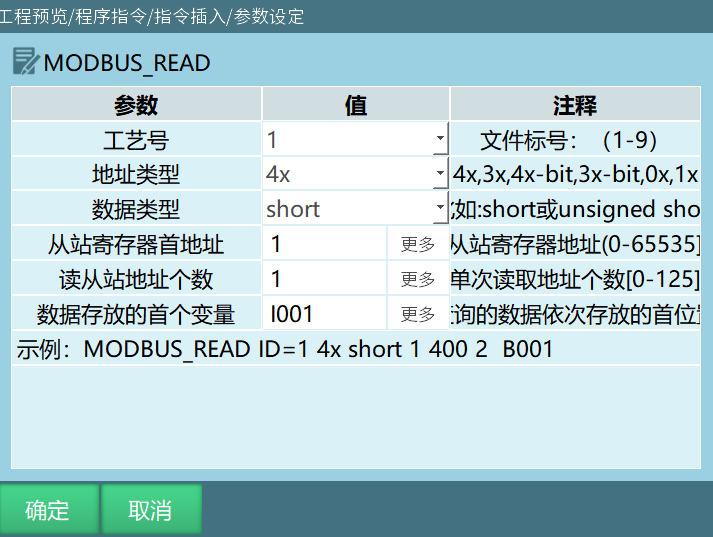
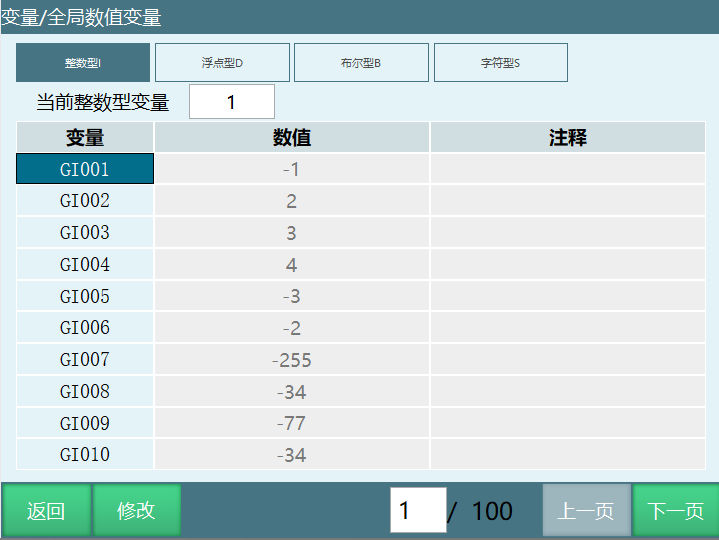
Example 1: Address type 4X, first variable for data storage is GI001, slave start address 1, read slave address count 10.
Example: Execute Modbus read instruction as shown below, read Modbus address 1-10 values into variables GI001-GI010.
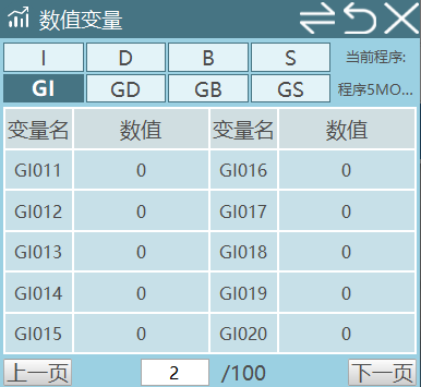
Example 2: Address type 3X-bit, first variable for data storage is GI001, slave start address 1, read slave address count 16.
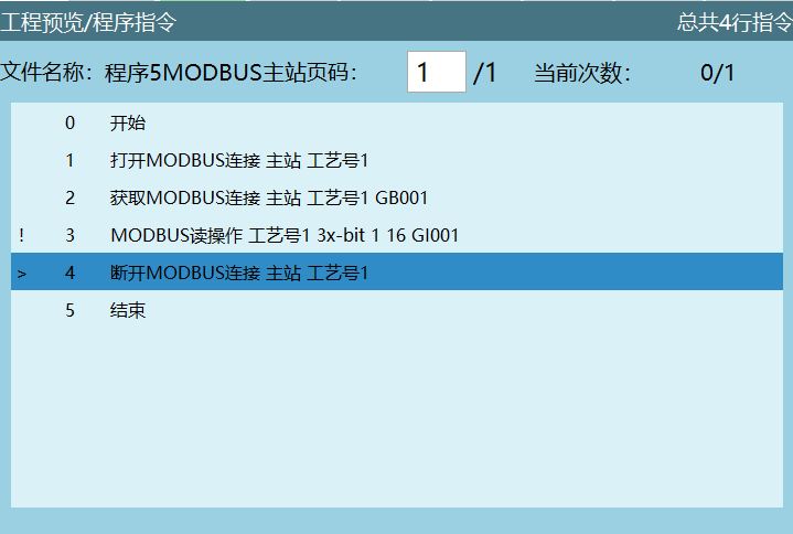
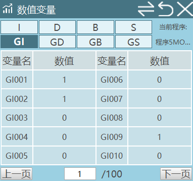
Example: The value stored at Modbus address 1 is 259, represented in 16-bit binary as 0000 0001 0000 0011. Store the 16-bit value sequentially into 16 variables (from the selected first variable, store the 16-bit original code from right to left).
The first variable for data storage is GI001. After converting 259 to binary, store each bit from right to left into GI001-GI016.
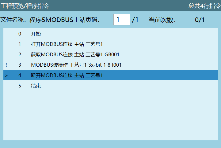
Example 3: Address type 3X-bit, first variable for data storage is I001, slave start address 1, read slave address count 8.
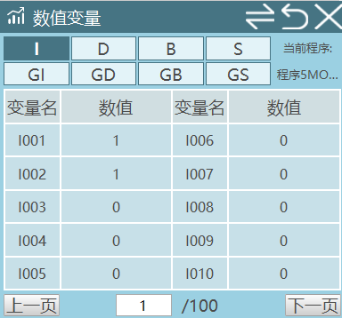
The value stored at Modbus address 1 is 259, represented in 16-bit binary as 0000 0001 0000 0011. Since the selected read slave address count is 8, execute Modbus read instruction, store 8 values sequentially (from the selected first variable, store from right to left).
The first variable for data storage is I001. After converting 259 to binary, store the 8 read values (0000 0011) from right to left into I001-I008.
Notes:
When address type is 3X-bit, the slave address count range is [0,16].
When address type is 3X-bit, the 17th bit stored in the variable is the sign bit, 0 means positive, 1 means negative.
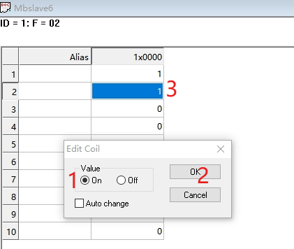
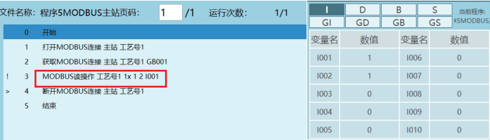
Example 4: Address type 1X, first variable for data storage is I001, slave start address 1, read slave address count 1.
Example: As shown below, 0X and 1X only have "0" and "1" two states. When Value is selected as On, it means 1. When selected as Off, it means 0. After executing the modbus read instruction, store the read corresponding address status into the variable.
Example 5: Address type 3X, first variable for data storage is S001, slave start address 1, read slave address count 5.
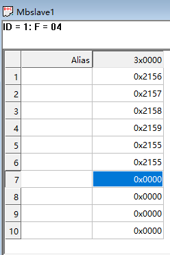
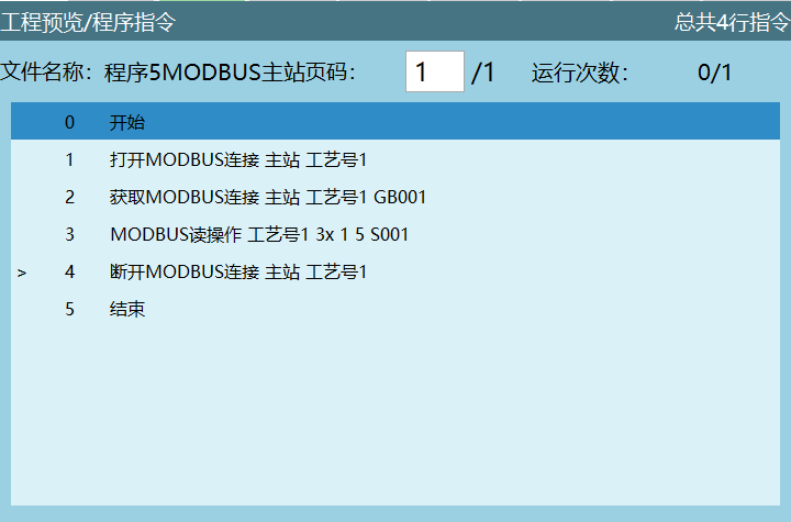
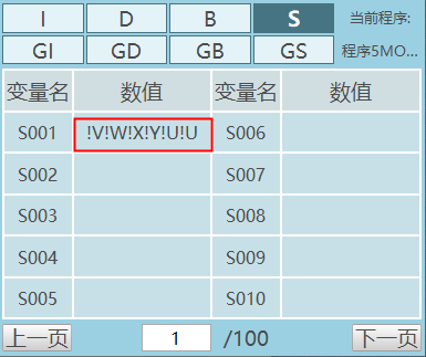
Execution effect: After executing the instruction, store the read master address 1-5 values into variable S001. Addresses exceeding the read address count cannot be read.
Notes:
- When reading characters, all read values will be stored into one variable. Unlike integer, floating-point, and boolean variables, it will not sequentially store into other variables based on the set start address and read slave address count.
Example: If the first variable set is S001, all read values will be stored into S001.
When selecting to read character variables, change the address Format to hexadecimal Hex.
Two hexadecimal numbers represent one ASCII character. For example, in the figure above, 0X2156, 21 represents one character, 56 represents one character. For specific read characters, refer to the ASCII code table.
Example 6: Address type 3X, first variable for data storage is D001, slave start address 1, read slave address count 10.
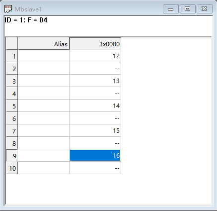
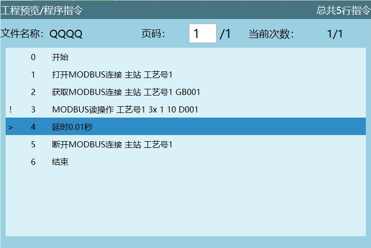
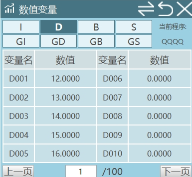
Execution effect: Execute Modbus read instruction to store the read floating-point numbers into D001-D005.
Note: Since 2 address codes in the register represent one floating-point number, the "read slave address count" should be even, and when reading floating-point variables, the address Format needs to be changed to Float CD AB.
MODBUS_WRITE - MODBUS Write Instruction
Format: MODBUS_WRITE [Instruction Name] ID [Process Number] 4X /4X-bit/ 0X [Address Type] B001 [First Variable for Data Storage] 1 [Slave Register Start Address] 5 [Write Slave Address Count].
Function: This instruction is used to write variables into the corresponding address positions in the slave register through Modbus.
Parameters:
| Parameter | Description |
|---|---|
| Process Number | Range [1,9]. The process number selected in the instruction must match the process number selected in the modbus parameter interface |
| Address Type | 4X: Write the value in the variable into the address code 4X-bit: Compose the variables into a 16-bit binary code and write into the address code 0X: Write the variable value into the address code, only "0" and "1" two states. If the variable has a value, write 1. If the variable has no value, write 0 |
| First Variable for Data Storage | Variable type to write |
| Slave Register Start Address | First address to start writing. If the start address is 5, the write instruction will start writing from the 5th address of modbus |
| Write Slave Address Count | Number of addresses to write. If the write address count is 3, it means write 3 addresses from the start address (including the start address) |
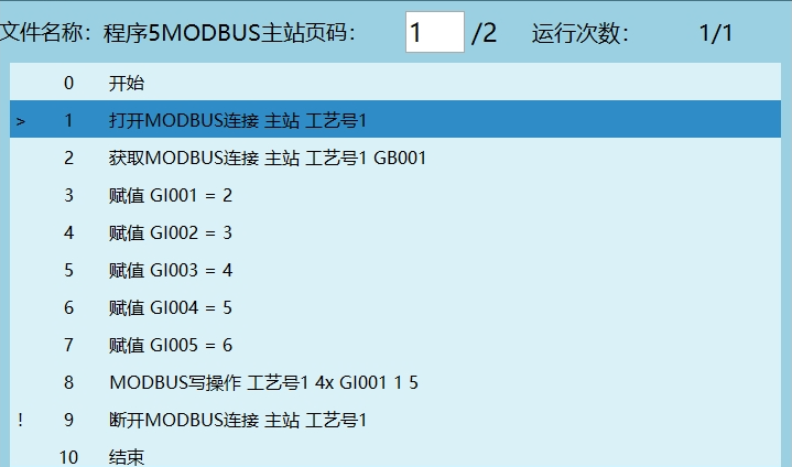
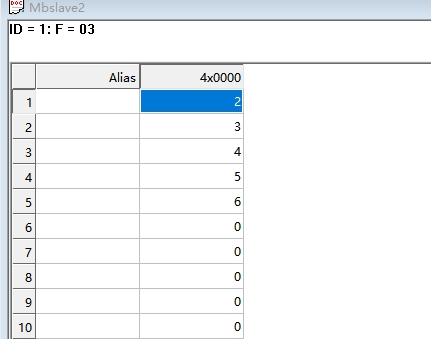
Example 1: Address type 4X, first variable for data storage is GI001, slave start address 1, write slave address count 5.
Execute modbus write instruction, will write the assigned variable values into the corresponding modbus address codes - GI001 value writes to modbus address 1, GI002 value writes to modbus address 2, sequentially until modbus address 5 write is complete.
Note: When MODBUS_WRITE instruction "first variable for data storage".
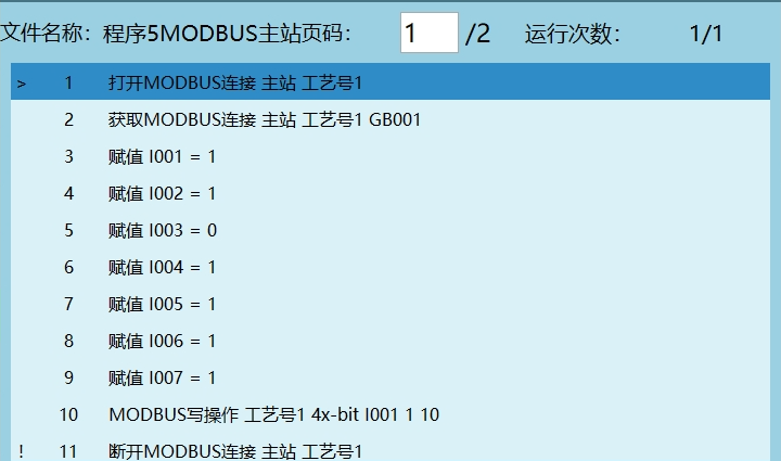
Example 2: Address type 4X-bit, first variable for data storage is I001, slave start address 1, write slave address count 10.
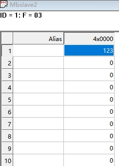
As shown below, I001=1 corresponds to address 1, I002=2 corresponds to address 2, I003=0 corresponds to address 3, I004=4 corresponds to address 4, I005=5 corresponds to address 5, I006=6 corresponds to address 6, I007=1 corresponds to address 7. I008, I009, I010 correspond to address 8, address 9, address 10 respectively. Since I008, I009, I010 are not assigned, they default to 0.
Therefore, the values assigned by I001-I010 are represented in binary (from left to right) as 00 0111 1011, 00 0111 1011 converted to decimal is 123.
Notes:
When address type is 4X-bit, the address count range is [0,16].
When address type is 4X-bit, the 17th bit stored in the variable is the sign bit, 0 means positive, 1 means negative.
Example 3: Address type 4X, first variable for data storage is GS001, slave start address 1, write slave address count 5.
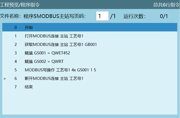
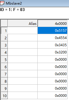
Execution effect: Execute Modbus write instruction to write the value of character variable GS001 into the address.
Notes:
Character variables can only be written to one address, will not sequentially write.
Example: If the first variable set is GS001, write count is 5, in the program assign values to variables GS001, GS002, GS003, GS004, GS005. Execute modbus write instruction will only write the value of variable GS001 into the address, GS002-GS005 values cannot be written.
Change the address Format to hexadecimal Hex.
One address code corresponds to two characters, one character corresponds to two hexadecimal digits.
For example, in the figure above GS001=QWET452, Q converts to hexadecimal 51, W converts to hexadecimal 57, characters QW convert to hexadecimal and write to address 1, characters ET write to address 2, characters 45 write to address 3, character 2 writes to the first digit of address 4. Whether the written values are correct can be verified against the ASCII code table.
Modbus Slave
| Parameter | Description |
|---|---|
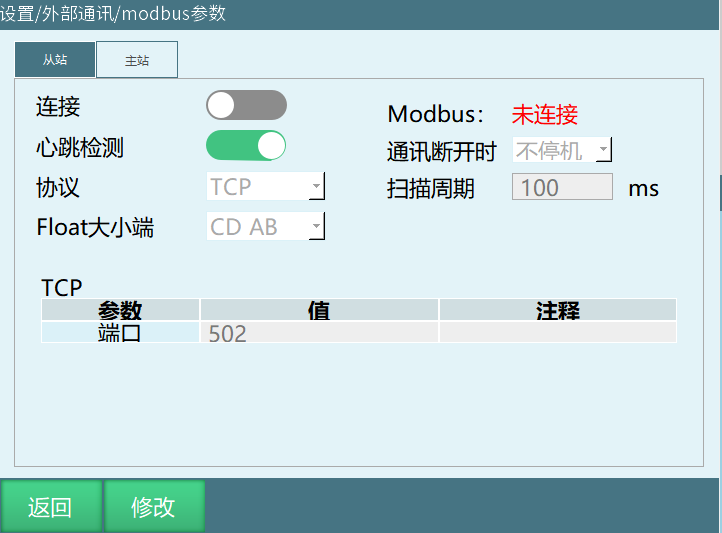
| Connection | After opening the connection enable switch, connect to Modbus. Without opening the enable, Modbus cannot connect successfully |
| Modbus | Monitor Modbus connection status |
| Heartbeat Detection | After opening, used to detect the send/receive frequency between Modbus and the controller. After disconnecting Modbus connection, heartbeat detection shows data send/receive closed |
| Communication Disconnect - Stop | When Modbus communication disconnects, robot powers off |
| Communication Disconnect - No Stop | When Modbus communication disconnects, robot does not power off |
| Protocol-RTU | Serial port 232, 485 communication |
| Protocol-TCP | TCP protocol |
| Scan Cycle | The cycle for the system to scan data within the Modbus range |
The system default timeout is 500ms. If no data is received within 500ms, it will automatically disconnect.
Modbus Poll Slave Connection
TCP Protocol
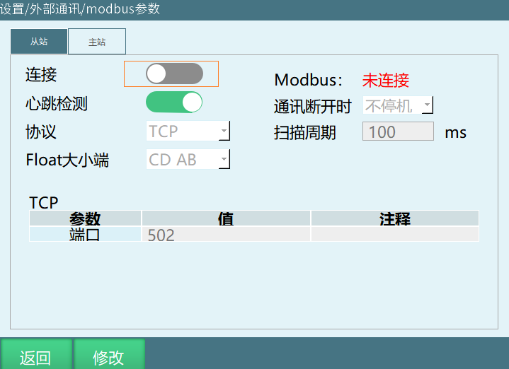
Click Settings - Modbus Settings - Modbus Parameters, enter the Modbus parameter interface, open the connection switch.
Open ModbusPoll software.
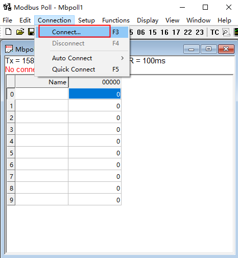
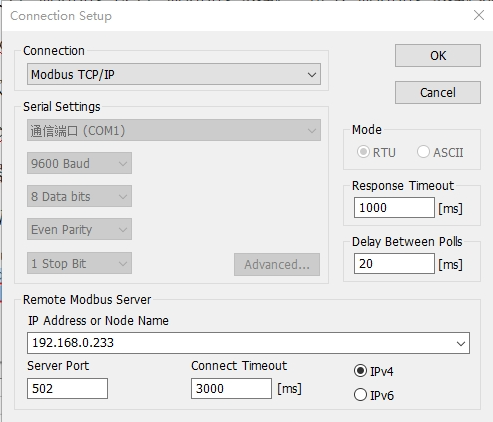
After opening the software, click Connection, select Connect, enter the Connection Setup interface.
- Connection select ModbusTCP/IP, IP Address is the currently connected controller IP.
Set the parameters (image parameters are for example only), click OK.
Note: The IP address is the currently connected controller's IP. When selecting TCP protocol, the host's IP network segment must be consistent with the controller's IP network segment.
The teach pendant page shows connected. If the Modbus parameter interface shows connected and disconnected flashing, you need to change the Scan Rate parameter from 1000ms to 100ms in Setup - Read/Write Definition.
After Modbus connection is successful, you can control the robot through address codes.
Example 1: Modbus switch servo status;
4X type address code 29 write 2, servo stop;
4X type address code 29 write 1, servo ready.
Operation Method:
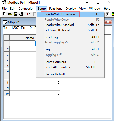
- Click Setup - Read/Write Definition.
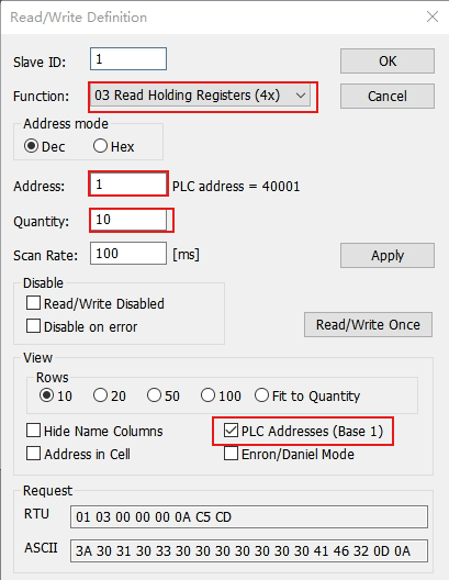
- Enter the Read/Write Definition interface, select address type as 4X, set start address Address, address count Quantity, check PLC Addresses (Base 1). After setting parameters, click OK to enter values in the corresponding address codes.
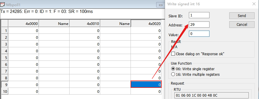
- Double-click the corresponding address, fill in the relevant address code:
Address code 29, Value write 1, servo status switches to ready;
Address code 29, Value write 2, servo status switches to servo stop.
RTU Protocol
232 Communication
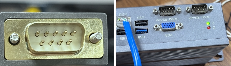
232 communication wiring:
Pin 2 of the 232 serial cable connects to pin 3 of the controller COM2_RS-232 port;
Pin 3 of the 232 serial cable connects to pin 2 of the controller COM2_RS-232 port;
Pin 5 of the 232 serial cable connects to pin 5 of the controller COM2_RS-232 port.
After wiring is complete, open ModbusPoll software:
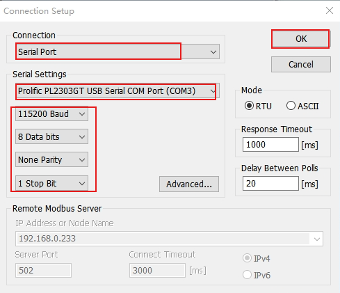
Click Connection, select Connect, enter the Connection Setup interface, as shown below:
- Connection select Serial Port, Serial Setting select the recognized serial port number, set the parameters (image parameters are for example only), click OK.
- Modbus connection successful.
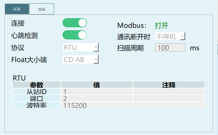
- After Modbus connection is successful, you can control the robot through address codes. The address codes for specific functions can be found in the "Modbus Address Code List".
485 Communication
485 communication wiring:
Pin 1 of the 485 serial cable connects to pin 2 of the controller COM1_RS-485 port;
Pin 2 of the 485 serial cable connects to pin 1 of the controller COM1_RS-485 port.
After wiring is complete, open ModbusPoll software.
Click Connection, select Connect, enter the Connection Setup interface.
- Connection select Serial Port, Serial Setting select the recognized serial port number, set the parameters (image parameters are for example only), click OK.
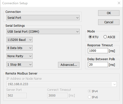
- Modbus connection successful.
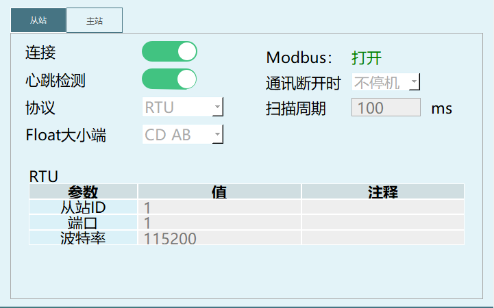
Description:
- For 232, 485 communication, pay attention to filling in the correct port number.
Modbus Master
| Parameter | Description |
|---|---|
| Process Number | Process number for master connection, supports 1-9 process numbers |
| Protocol | TCP, RTU (232, 485 communication) |
| Modbus | Monitor Modbus master connection status |
| Address Offset - Address Auto -1 | Start address is 1 |
| Address Offset - Address Unchanged | Start address is 0 |
| Float Big-Endian - ABCD | Sequential ordering, store data in natural byte order. For example, 32-bit integer 0x12345678, storage order is 12 34 56 78 |
| Float Big-Endian - BADC | Single word reversal, reverse the byte order within each word (2 bytes). Storage order of 32-bit integer 0x12345678 becomes 34 12 78 56 |
| Float Big-Endian - CDAB | Double word reversal, reverse the data in units of two words. Storage order of 32-bit integer 0x12345678 becomes 56 78 12 34 |
| Float Big-Endian - DCBA | Reverse ordering, completely reverse the byte order of the entire data. Storage order of 32-bit integer 0x12345678 becomes 78 56 34 12 |
Modbus Slave Master Connection
TCP Protocol
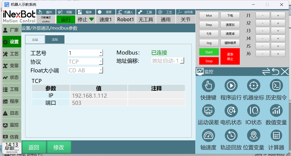
As shown below, the IP address during TCP communication is the current host address, not the currently connected controller IP.
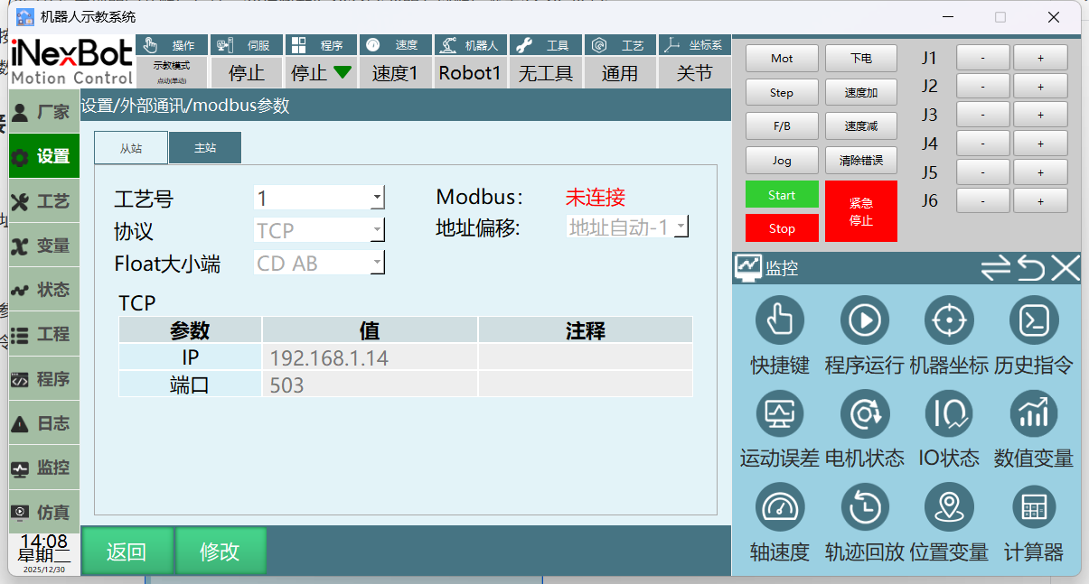
Set parameters in the Modbus master parameter interface.
Create a new project, insert modbus instruction.
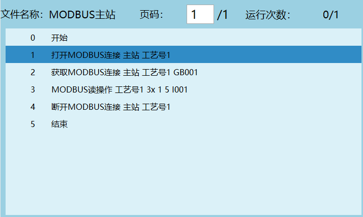
Open Modbus Slave software.
After opening the software, click Connection, select Connect, enter the Connection Setup interface.
- Connection select ModbusTCP/IP, Port number must match the port number set in the Modbus parameter interface, click OK.
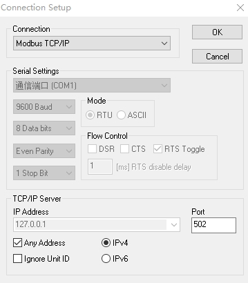
- Execute step 2 project interface to open MODBUS connection instruction, Modbus master connection successful.
RTU Protocol
For 232, 485 communication wiring methods, refer to the Modbus Poll Slave Connection section.
EC-RTU
Usage is the same as Modbus-RTU.
Port is fixed, port setting is not open, currently only adapted for specific robot end IO.
Modbus Master Read Parameters
Function: Read parameters from Modbus address into variables.
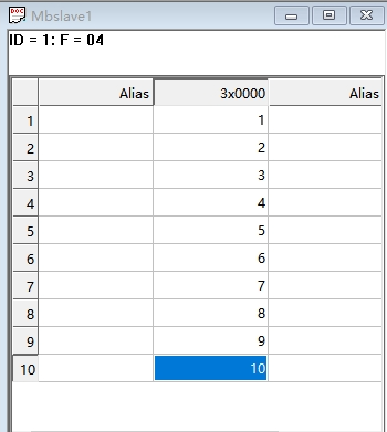
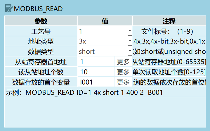
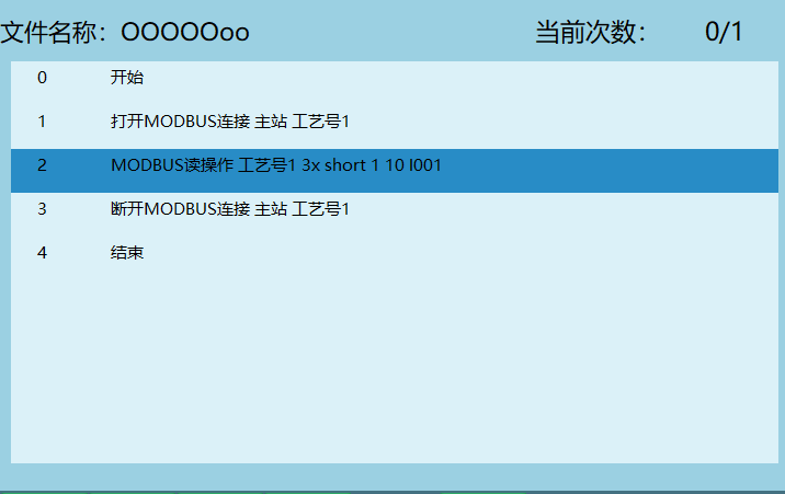
Example Description:
Open Modbus master communication;
If Modbus master connection is successful, variable GB001=1, otherwise GB001=0;
Execute Modbus read instruction to read the values from Modbus slave corresponding addresses into variables. First variable I001, read address count 10, after executing instruction, read master address 1-10 values into variables I001-I010;
Disconnect Modbus master connection.
Modbus Master Write Parameters
Function: Write the assigned variable values into the corresponding addresses, as shown in the schematic below.
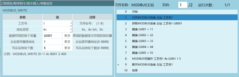
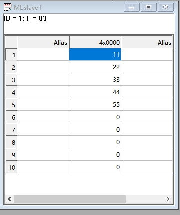
Example Description:
Open Modbus master communication;
If Modbus master connection is successful, variable GB001=1, otherwise GB001=0;
Lines 3-8 assign values to the variables to be written;
Execute Modbus write instruction to write GI001-GI005 values into master address 1-5;
Disconnect Modbus master connection.
Modbus Modify Address Code
Insert USB drive, export controller configuration.
Find the modbusAddr.json file in the exported configuration file.
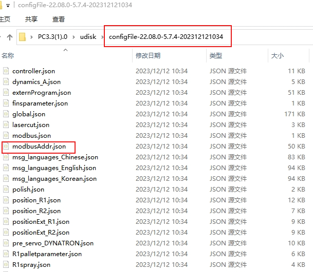
- Open with text editing software like Notepad++
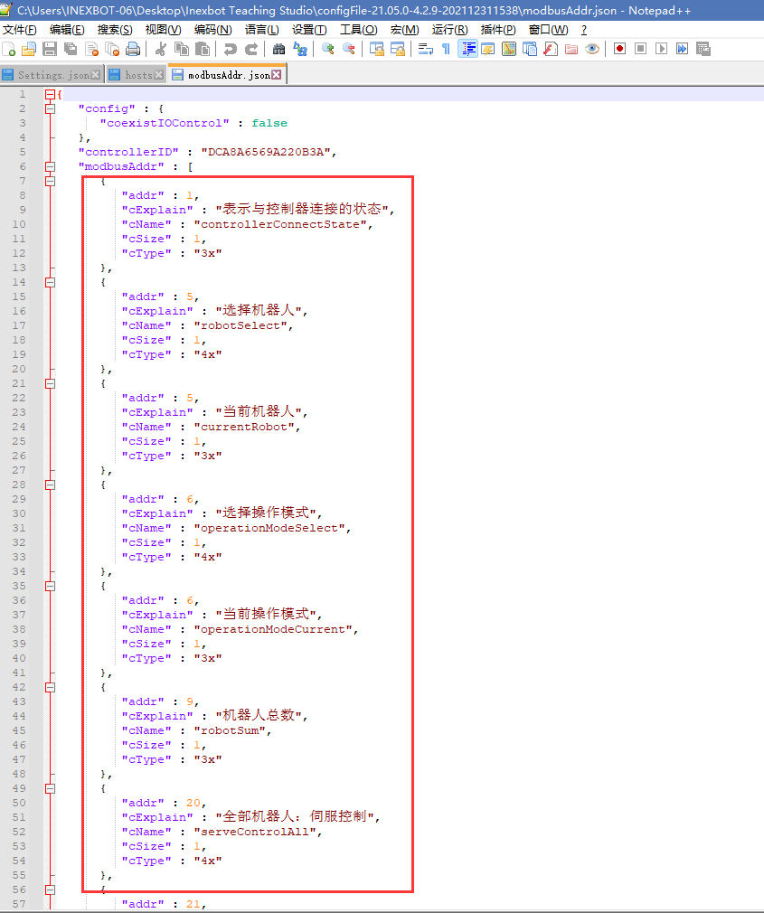
- After opening, you can see a set of address code parameters contained in {} (the system will automatically generate a set of original address codes).
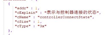
- Modify the address by directly changing the number after addr. When the number is 0, the address code function is invalid.
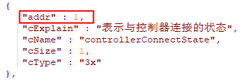
Note: The modified address code cannot be the same as other address codes, otherwise it will affect other functions.
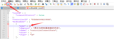
- After modification, click Save.
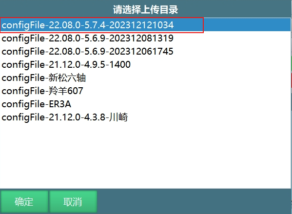
- Then re-import the modified configuration file, restart to take effect.
Modbus Usage
Modbus Remote Run Program
For how to run Modbus programs, refer to the "Teaching and Running" manual.
Modbus Modify Global Position Variables
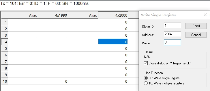
4X type address code 2004 write 0, represents GP point.
4X type address code 2004 write 1, represents GE point.
As shown below, address code 2004 write 0, variable type is GP.
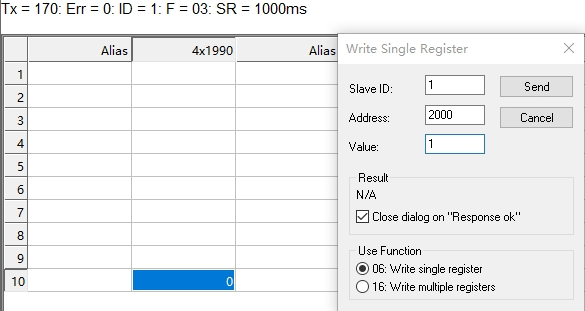
- The value written in 4X type address code 2000 represents the selected variable number, number range is 1-9999.
As shown below, address code 2000 write 1, select GP0001 variable:
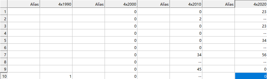
- Modify robot point position: address codes 2017-2028.
Change the Format of 2017-2028 to FloatCD AB, enter parameter values.
As shown, modify GP0001 variable robot point position to (34,45,23,23,34,56). Address codes starting from 2017 including 2017, every 2 address codes represent one axis value of the robot. That is 2017, 2018 represent axis 1 coordinates, 2019, 2020 represent axis 2 coordinates, 2021, 2022 represent axis 3 coordinates, 2023, 2024 represent axis 4 coordinates, 2025, 2026 represent axis 5 coordinates, 2027, 2028 represent axis 6 coordinates.
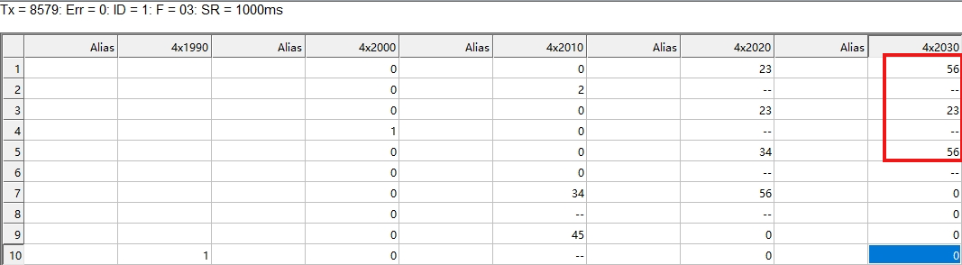
- Modify external axis point position: address codes 2031-2036, only supports 3 external axes.
Change the Format of 2031-2036 to FloatCD AB, then enter values.
- After modifying parameters, address code 2003 write 1, means write the modified value into the variable, i.e., save.
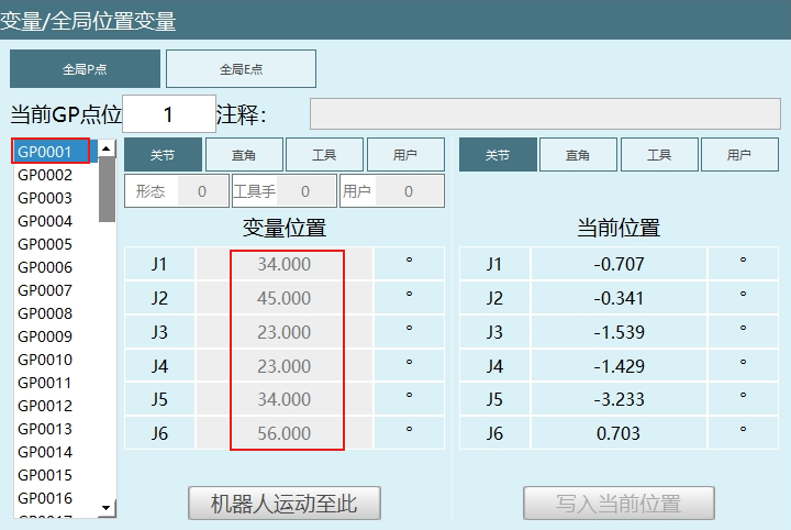
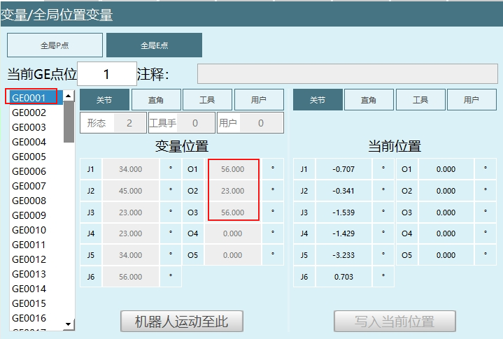
Modbus Write Read 100 Positions
Start address 3000, each GP point coordinate system occupies one bit, configuration occupies one bit. Each axis position occupies two bits.
Starting variable: GP0001.
As shown: address code 3000 represents GP0001's coordinate system, address code 3001 represents GP0001's configuration.
Address codes 3002, 3003 represent axis 1 position, 3004, 3005 represent axis 2 position, 3006, 3007 represent axis 3 position, 3008, 3009 represent axis 4 position, 3010, 3011 represent axis 5 position, 3012, 3013 represent axis 6 position.
Address codes 3014, 3015 represent GP0002's coordinates, configuration, address codes 3016-3027 represent GP0002 coordinate axis positions, and so on.
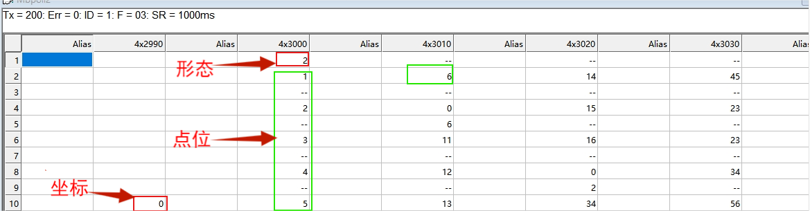
Note: The address code Format for each axis position is FloatCD AB.
Modbus Multi-Master Connection
Connect the computer and one or more touch panels to the controller through a switch.
The controller acts as the slave, Modbus Poll and touch panels act as masters. Modbus Poll can open multiple instances as multiple masters, currently supports up to 9 masters connected simultaneously.
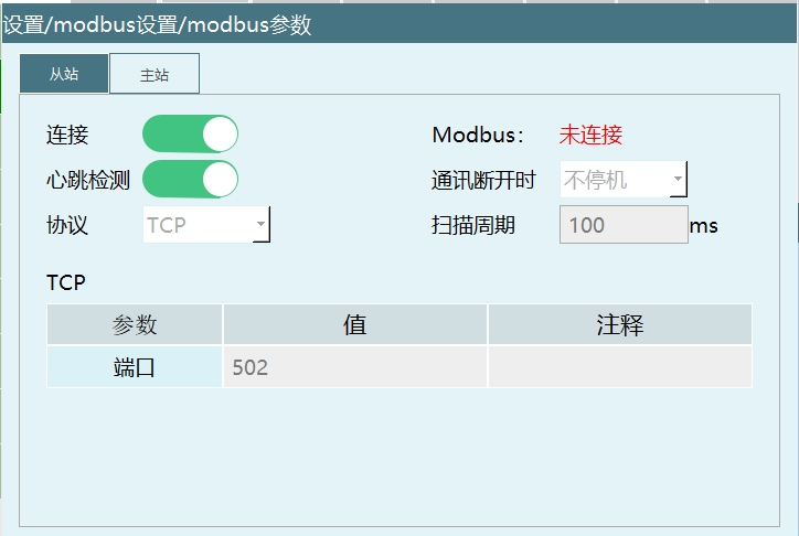
Modbus Poll click connection select connect, connection type select TCP, IP address and port number must match the teach pendant, scan cycle must match the teach pendant.
Modbus Poll and touch panels can control the robot simultaneously.
Modbus and IO Priority
Enter the controller through the display, find ModbusAddr.json in the robot/config/ directory, or export the configuration and modify the ModbusAddr.json file.
Open ModbusAddr.json.
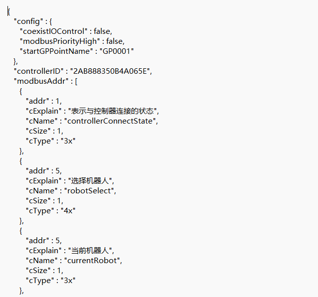
coexistIOControl: false means Modbus and IO do not share; when Modbus is connected, IO cannot control the robot.
coexistIOControl: true means Modbus and IO share, Modbus and IO can control the robot simultaneously.
When modbus and IO share, the job file called is the job file in [Remote Program Settings], and [Operation Parameters - Reservation Mode] must be opened.
- coexistIOControl: false, ModbusPriorityHigh: false/true have no effect.
Modbus default priority is high and when Modbus is connected, IO cannot control.
- coexistIOControl: true, ModbusPriorityHigh: false.
Means modbus and IO share and IO priority is high. That is Modbus and IO can control the robot simultaneously, the breakpoints and current line running logic of modbus and IO execute according to the settings on the teach pendant.
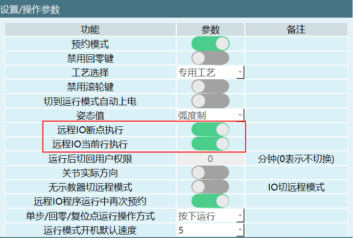
- When coexistIOControl: true, modbusPriorityHigh: true.
Means IO cannot run its own program, instead IO (settings on the teach pendant) controls the program selected by modbus as well as the run count and total count.
And when sharing, as long as the higher priority party is not connected, the other party's function is not available.
Modbus Touch Screen Usage Process
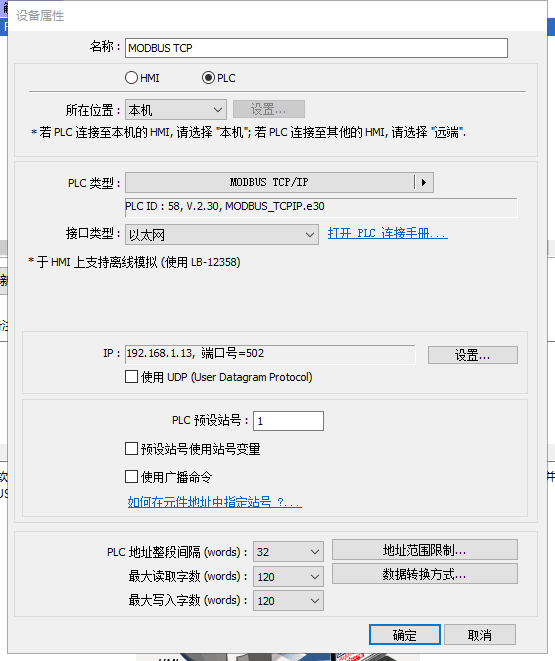
This section uses Weintek touch screen and modbusTCP protocol as an example; touch screen model is MT6071iP.
Write Program - Set Modbus Program - Set Modbus Parameters - Switch to Remote Mode - Touch Screen Preparation - Select Program - Run.
- Write Program
Write a program with the teach pendant, ensure it can run normally.
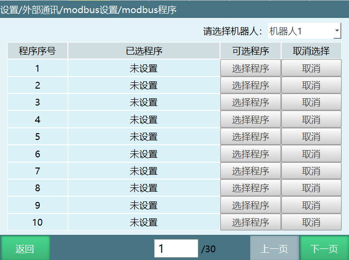
- Set Modbus Program
In "Settings - Modbus Settings - Modbus Program" set the program. After successful setting, the selected program list will display the program name. A total of 1000 programs can be set.
- Set Modbus Parameters
In "Settings - Modbus Settings - Modbus Parameters" set the protocol to TCP, set the controller as master/slave to slave, do not modify IP, set port to 502, open connection enable; restart the controller to take effect.
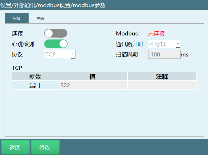
Modbus Parameter Description:
| Parameter | Description |
|---|---|
| Connection | After Modbus setup is complete, need to open the connection button. Right side can view connection status |
| Heartbeat Detection | After opening, used to detect the send/receive frequency between Modbus and the controller. After disconnecting Modbus connection, heartbeat detection shows data send/receive closed |
| Protocol | Divided into TCP protocol, RTU protocol |
| Master/Slave | Master, slave |
| TCP Parameters-IP | Modbus device IP address, only effective when set as master |
| TCP Parameters-Port | Modbus device port |
| RTU Parameters-Slave ID | Default is 1 |
| RTU Parameters-Port | Controller serial port number |
| RTU Parameters-Baud Rate | Fill in the corresponding baud rate of the touch screen |
- Switch to Remote Mode
Rotate the mode selection key to the remote mode position or click the mode status in the program, select remote mode.
Note: When the controller is simultaneously connected to IO, Modbus device, and teach pendant, the priority of the three devices is teach pendant > Modbus device > IO device. After switching to remote mode, Modbus device is effective, IO device is ineffective. At this time, close the enable button in Modbus device, then IO is effective.
- Touch Screen Preparation
Connect the touch screen RJ45 network port, teach pendant network port, and controller "Teach Pendant" network port to the same switch.
Touch screen connects to controller IP: 192.168.1.13, port: 502.
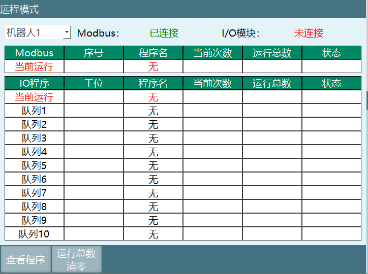
After the touch screen program is edited and run, the teach pendant remote interface Modbus Not Connected changes to Modbus Connected. As shown:
- Select Program
Use the touch screen to write 1 to 4x type address code 45, robot 1 selects demo program 1;
Use the touch screen to write 5 to 4x type address code 61, robot 1 sets run count to 5 (not effective). Use the touch screen to write 1 to 4x type address code 71, confirm modify run count (run count 5 becomes effective).
- Run
Use the touch screen to write 1 to 4x type address code 29, switch to servo ready;
Use the touch screen to write 1 to 4x type address code 19, run job file.
Q&A for Retrieval
Q: What is the function of the MODBUS_OPEN instruction?
A: The MODBUS_OPEN instruction is used to open Modbus communication connection.
Q: What is the function of the MODBUS_CLOSE instruction?
A: The MODBUS_CLOSE instruction is used to close Modbus communication connection.
Q: What is the function of the MODBUS_CONNECTION_STATUS instruction?
A: The MODBUS_CONNECTION_STATUS instruction is used to get the Modbus communication connection status. If connection is successful, variable value is 1. If connection fails, variable value is 0.
Q: What address types does the MODBUS_READ instruction support?
A: The MODBUS_READ instruction supports address types including: 4X, 3X, 4X-bit, 3X-bit, 0X, 1X.
Q: What address types does the MODBUS_WRITE instruction support?
A: The MODBUS_WRITE instruction supports address types including: 4X, 4X-bit, 0X.
Q: What communication protocols does the Modbus slave support?
A: The Modbus slave supports RTU (serial port 232, 485 communication) and TCP protocols.
Q: What communication protocols does the Modbus master support?
A: The Modbus master supports TCP and RTU (232, 485 communication) protocols.
Q: What are the Float big-endian options?
A: Float big-endian has four options: ABCD (sequential ordering), BADC (single word reversal), CDAB (double word reversal), DCBA (reverse ordering).
Q: How to modify Modbus address codes?
A: Steps to modify Modbus address codes: 1. Insert USB drive and export controller configuration; 2. Find the modbusAddr.json file in the exported configuration file; 3. Open with text editing software and modify the number after addr; 4. Save and re-import the configuration file, restart to take effect.
Q: How to set Modbus and IO priority?
A: Set priority by modifying the coexistIOControl and ModbusPriorityHigh parameters in the ModbusAddr.json file. When coexistIOControl is false, Modbus and IO do not share; when true, they can share, and ModbusPriorityHigh determines which has higher priority.
Q: How to use a touch screen to control the robot?
A: Process for using a touch screen to control the robot: Write Program → Set Modbus Program → Set Modbus Parameters → Switch to Remote Mode → Touch Screen Preparation → Select Program → Run.
Q: What should be noted when reading character variables?
A: When reading character variables, note: 1. All values are stored in one variable, will not sequentially store into other variables; 2. Address Format needs to be changed to hexadecimal Hex; 3. Two hexadecimal numbers represent one ASCII character.
Q: What should be noted when reading floating-point variables?
A: When reading floating-point variables, note: 1. "Read slave address count" should be even; 2. Address Format needs to be changed to Float CD AB.
Q: What is the address count range when address type is 3X-bit?
A: When address type is 3X-bit, the address count range is [0,16].
Q: What is the address count range when address type is 4X-bit?
A: When address type is 4X-bit, the address count range is [0,16].
Version History
| Version | Date | Changes | Author |
|---|---|---|---|
| 1.0.0 | 2026-06-24 | Initial version | jmz-09 |