1 TCP External Communication
When communicating with external devices, TCP communication can be selected.
2 Parameter Settings
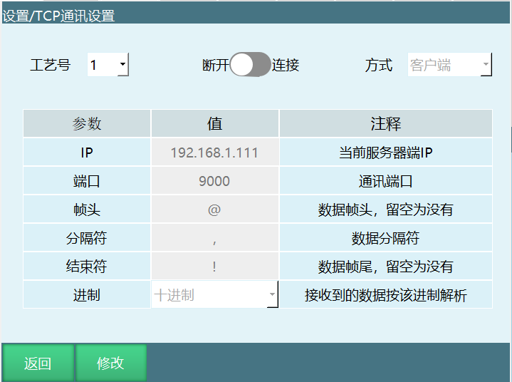
To set up TCP communication, enter the "Settings - TCP Communication Settings" screen.
2.1 Function Description
Process No.: Supports 9 process numbers.
Connection switch: When the mode is client, white means disconnected and green means connected; when the mode is server, white means closed and green means open (after connecting, this screen will prompt that the communication connection is successful).
Mode: Use the controller as a server or client (when the controller is a client or server, different process numbers can be used to communicate and send/receive data with multiple external devices; note: when the controller is a client and connects to multiple server devices with multiple process numbers, the IP and port between process numbers cannot be the same; when the controller is a server and connects to multiple client devices with multiple process numbers, the ports cannot be the same).
IP: When the controller acts as a server (mode selected as server), this is the controller IP and does not need to be modified. When the controller acts as a client, the IP of the external communication device must be set here.
Port: When the mode is server, this is the local listening port for clients to connect to; when the mode is client, this is the port for connecting to the server.
Frame header: The frame header used by the controller when receiving messages from external devices during data communication; can be modified.
Separator: The separator used by the controller when receiving messages from external devices during data communication; can be modified.
Terminator: The terminator used by the controller when receiving messages from external devices during data communication; can be modified.
Base: Select the corresponding base for the decimal or hexadecimal data to be received, then parse and output it in decimal.
2.2 Precautions
When connecting via TCP communication, first set the controller IP and the external device IP to the same subnet, such as 192.168.1.xxx. If the controller is set as the client, the external device is the server. Then set the IP and port in the network settings to be consistent with the IP and port in the external device's network debugging software. Turn on the connection switch, and a successful connection prompt is shown.
3 Network Communication Instructions
3.1 SENDMSG - Send Data
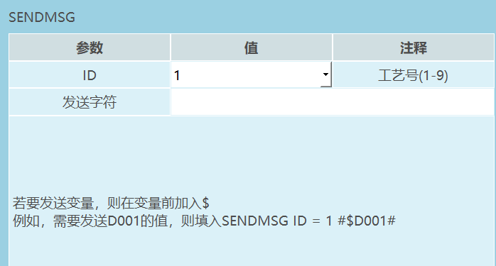
This instruction is used to send data to a connected external device. By selecting the corresponding process number, strings and variables can be sent.
Strings and variables can be sent in a mixed manner. Sending information to external devices does not use the frame header, separator, terminator or base set on the "Settings - TCP Communication Settings" screen.
To send a variable, add $ before the variable.
Parameter description:
| Parameter | Value | Comment |
|---|---|---|
| ID | Process number (1-9) | 1 |
| Send characters | To send a variable, add $ before the variable | For example, to send the value of D001, fill in SENDMSG ID =1#$D001# |
Example:
Prerequisite: GD001=123, I001=10
Need to send the data "The value of GD001 is 123,and the value of I001 is 10" to the host computer with network process number 3
Insert the SENDMSG instruction as:
- ID=1
- Send characters: The value of GD001 is $GD001,and the value of I001 is $I001
3.2 PARSEMSG - Parse Data
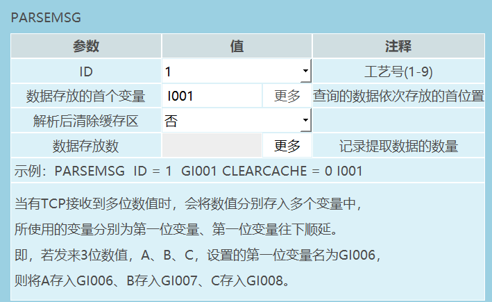
This instruction is used to parse a set of data sent from an external device.
This instruction stores the data sent from the external device in multiple global variables respectively. The first variable to be set in this instruction is the first variable.
Do not clear the cache after parsing: The data sent by the external device is temporarily stored in the controller's cache;
- a. If the cache is not cleared, after the first parsing and before the next set of data is sent, the data still remains in the cache;
- b. If the cache is cleared, after the first parsing is completed, the data in the cache is cleared.
Parameter description:
| Parameter | Value | Comment |
|---|---|---|
| ID | Process number (1-9) | 1 |
| First variable for data storage | 1001 | The first position where more queried data is stored in sequence |
| Clear cache after parsing | No | 0 or 1 |
| Number of stored data | Records the number of extracted data | - |
Example: PARSEMSG ID=1 GI001 CLEARCACHE=01001
When TCP receives multiple numeric values, the values are stored in multiple variables respectively. The variables used are the first variable and the variables sequentially following the first variable.
That is, if 3 numeric values A, B, C are sent and the set first variable name is GI006, then A is stored in GI006, B in GI007, and C in GI008.
Complete example:
Frame header: @ Separator: , Terminator: !
The first variable type of the PARSEMSG instruction is GDOUBLE, and the first variable name is GD003.
External device sends data: @,12,6,47,102,77.88,!
Then the EXPLAIN instruction stores these 5 numeric values in GD003, GD004, GD005, GD006 and GD007 respectively.
GD003=12 GD004=6 GD005=47 GD006=102 GD007=77.88
Clear cache after parsing: Yes or No
3.3 READCOMM - Read Data
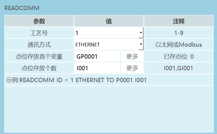
Read the points sent via Ethernet or Modbus and store them in position variables, and store the count in numeric variables.
Note: The usage is the same as "External Point Function"; this instruction currently only supports Modbus.
Parameter description:
| Parameter | Value | Comment |
|---|---|---|
| Process number | 1 | 1-9 |
| Communication method | ETHERNET | Ethernet or Modbus |
| First variable for point storage | GP0001 | Stored points: 0 |
| Number of stored points | 1001 | 1001,GI001 |
Example: READCOMM ID =1 ETHERNET TO P0001 1001
- Process number: The network communication process number to be opened.
- Communication method: Use Ethernet communication or Modbus communication.
- First variable for point storage: Global position variable/local position variable can be selected.
- Number of stored points: The number of received points to store.
3.4 OPENMSG - Open Data
Connect communication: open the network communication of the corresponding process number. After running the OPENMSG instruction, the communication is opened.
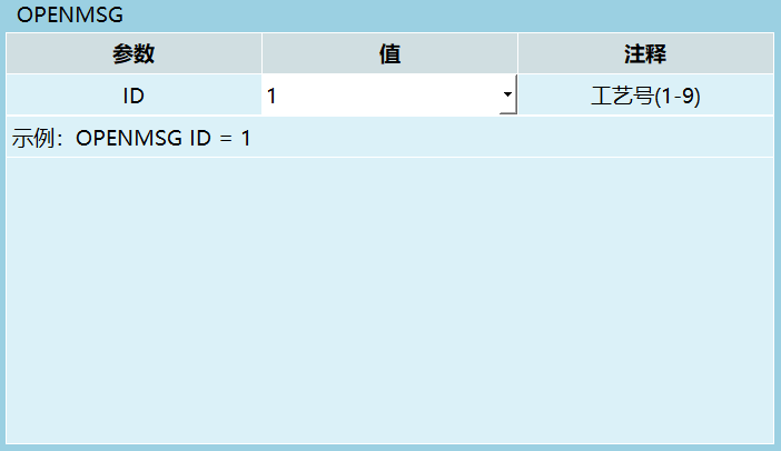
Parameter description:
| Parameter | Value | Comment |
|---|---|---|
| ID | 1 | Process number (1-9) |
Example: OPENMSG ID=1
- Process number: The process number whose network communication is to be connected.
3.5 CLOSEMSG - Close Data
Disconnect communication: close the network communication of the corresponding process number. After running the CLOSEMSG instruction, the communication is closed.
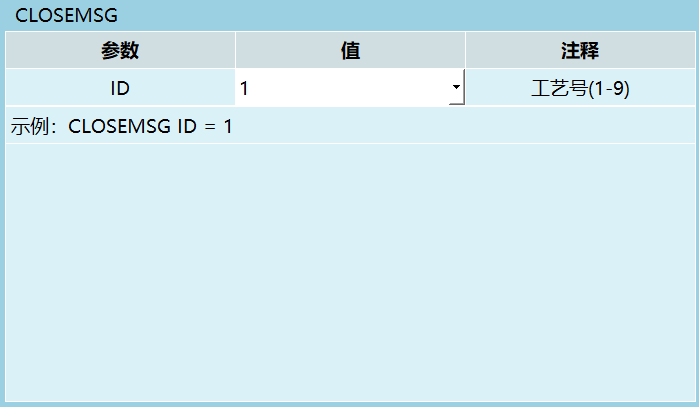
Parameter description:
| Parameter | Value | Comment |
|---|---|---|
| ID | 1 | Process number (1-9) |
Example: CLOSEMSG ID=1
- Process number: The process number whose network communication is to be disconnected.
3.6 PRINT - Output Information
A screen output instruction that displays content on the teach pendant in three forms. It can output custom characters or variable data.
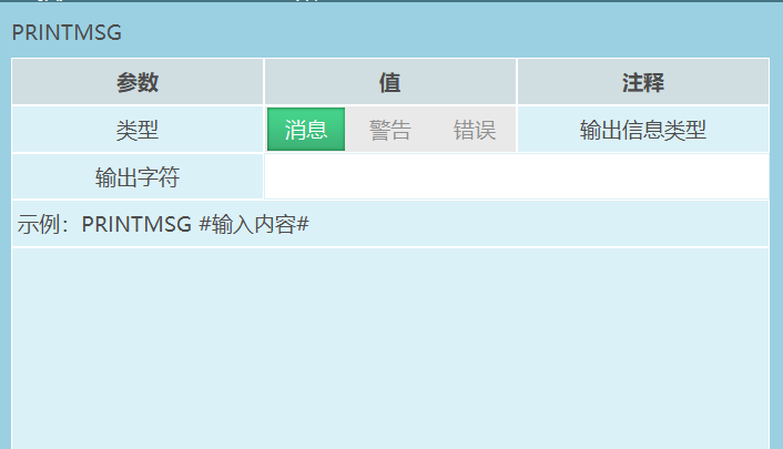
Type: Currently divided into three types: message, warning, error.
Output characters: Output characters. Any characters can be entered (escape characters supported), and variables can also be output. For example, for variable GD001 with GD001=10, enter $GD001 in the "message, warning, error" instructions of the output information respectively.
When running or stepping through this instruction, what pops up in the lower right corner of the teach pendant is:
- White message content: 10;
- Yellow warning content: 10;
- Red error content: 10.
3.7 MSG_CONN_ST - Get Connection Status
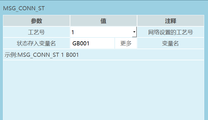
Parameter description:
| Parameter | Value | Comment |
|---|---|---|
| Process number | 1 | The process number in the network settings |
| Variable name for status storage | GB001 | More variable names |
Example: MSG_CONN_ST1 B001
- Process number: The process number whose network communication connection status is to be judged.
- Variable name for status storage: Store the communication status into a local BOOL variable or a global GBOOL variable.
Read the network communication status of the current process number into the corresponding global boolean or local boolean variable. If the communication is normal, the stored value is 1; if the communication fails, the stored value is 0.
4 Data Upload
4.1 Basic Settings
The data upload function can automatically collect and upload the current robot running status and parameters at regular intervals, integrate the data into csv and txt files, and upload them to the specified server.
In Settings - Data Upload, click the [Modify] button to set the parameters required for connecting to the ftp server.
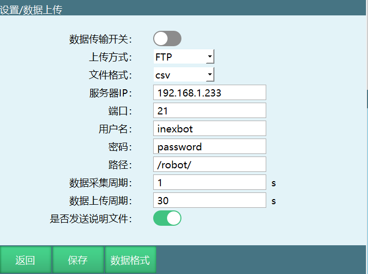
Parameter description:
| Parameter | Description |
|---|---|
| Data transmission switch | When turned on, it starts connecting to the ftp server and uploading data. Turn on this switch only after all parameters are filled in. After this switch is turned on, data collection and upload will start automatically at boot. |
| Upload method | Currently only the ftp protocol is supported. Therefore, before using this function, please have an ftp server first. |
| File format | Currently supports csv and txt formats. The file content is the same, but the file format is different. The csv format is more convenient for data statistics. |
| Server IP | The IP address of the ftp server. Ensure that this controller and the ftp server are on the same network and have the same gateway (the controller gateway can be viewed and modified in Settings - System Settings - IP Settings). |
| Port | The port used by the ftp protocol of the ftp server. The default port commonly used by the ftp protocol is 21. |
| Username | The username used to log in to the ftp server. A user must first be created on the ftp server. |
| Password | The password used to log in to the ftp server. |
| Path | The path where files are uploaded to the ftp server. This path is relative to the ftp root directory. |
| Data collection period | According to the set time, the controller collects the current data once at intervals and stores it in the file to be sent. |
| Data upload period | According to the set time, the controller sends the file with collected data to the directory specified on the ftp server at intervals. |
| Whether to send the description file | The description file is sent before the first data file is sent after boot or after turning on the [Data Transmission Switch]. The content can be customized, generally used to describe information such as the current robot sequence number. If this switch is off, the description file is not sent. |
4.2 Data Format
After configuring the ftp connection parameters, the data format in the data file to be sent needs to be configured. When setting the data format, special strings are used to represent the parameters to be sent. For example, to send the current date in the format "2019-03-07", fill in the data format as follows: "$Y$%-$m$%-$d$%" (without the quotation marks).
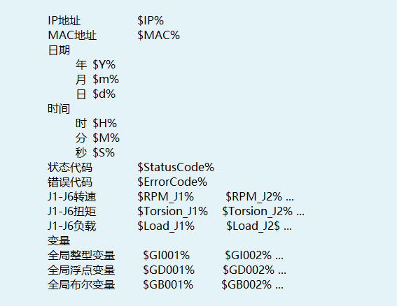
If the generated file is in csv format, each item must be separated by an English comma.
Special strings representing parameters:
| Parameter type | Special string |
|---|---|
| IP address | $IP% |
| MAC address | $MAC% |
| Date - year | $Y% |
| Date - month | $m% |
| Date - day | $d% |
| Time - hour | $H% |
| Time - minute | $M% |
| Time - second | $S% |
| Status code | $StatusCode% |
| Error code | $ErrorCode% |
| J1-J6 speed | $RPM_J1%,$RPM_J2%.. |
| J1-J6 torque | $Torsion_J1%,$Torsion_J2%... |
| J1-J6 load | $Load_J1%,$Load_J2%... |
| Global integer variables | $GI001%,$GI002%... |
| Global float variables | $GD001%,$GD002%... |
| Global boolean variables | $GB001%,$GB002%... |
Generated csv file example:
The expected result is as follows:
Description document file name: Robot-R1_Year-Month-Day_Hour:Minute:Second_INFO
Description document content: Robot-R1,Year-Month-Day,Hour:Minute:Second,Local IP,Local MAC,Technical Department,Machined Parts,Axis 1 Motor Speed,Axis 2 Motor Speed,Axis 3 Motor Speed,Axis 4 Motor Speed,Axis 5 Motor Speed,Axis 6 Motor Speed,Axis 1 Motor Torque,Axis 2 Motor Torque,Axis 3 Motor Torque,Axis 4 Motor Torque,Axis 5 Motor Torque,Axis 6 Motor Torque,Axis 1 Motor Load,Axis 2 Motor Load,Axis 3 Motor Load,Axis 4 Motor Load,Axis 5 Motor Load,Axis 6 Motor Load,Current Controller Status,Current Error Code.
Data document file name: Robot-R1_Year-Month-Day_Hour:Minute:Second_DATA
Data content: Robot-R1,Year-Month-Day,Hour:Minute:Second,Local IP,Local MAC,Axis 1 Motor Speed,Axis 2 Motor Speed,Axis 3 Motor Speed,Axis 4 Motor Speed,Axis 5 Motor Speed,Axis 6 Motor Speed,Axis 1 Motor Torque,Axis 2 Motor Torque,Axis 3 Motor Torque,Axis 4 Motor Torque,Axis 5 Motor Torque,Axis 6 Motor Torque,Axis 1 Motor Load,Axis 2 Motor Load,Axis 3 Motor Load,Axis 4 Motor Load,Axis 5 Motor Load,Axis 6 Motor Load,Current Controller Status,Current Error Code.
The data format written is as follows:
Description document file name: Robot-R1_ $Y%-$m%-$d%_ $H%:$M%:$S%_INFO
Description content: Robot-R1,$Y%-$m%-$d%,$H%:$M%:$S%,$IP%,$MAC%,技术部,加工零件,$RPM_J1%,$RPM_J2%,$RPM_J3%,$RPM_J4%,$RPM_J5%,$RPM_J6%,$Torsion_J1%,$Torsion_J2%,$Torsion_J3%,$Torsion_J4%,$Torsion_J5%,$Torsion_J6%,$Load_J1%,$Load_J2%,$Load_J3%,$Load_J4%,$Load_J5%,$Load_J6%,$StatusCode%,$ErrorCode%
Data document file name: Robot-R1_ $Y%-$m%-$d%_ $H%:$M%:$S%_DATA
Data content: Robot-R1,$Y%-$m%-$d%,$H%:$M%:$S%,$IP%,$MAC%,$RPM_J1%,$RPM_J2%,$RPM_J3%,$RPM_J4%,$RPM_J5%,$RPM_J6%,$Torsion_J1%,$Torsion_J2%,$Torsion_J3%,$Torsion_J4%,$Torsion_J5%,$Torsion_J6%,$Load_J1%,$Load_J2%,$Load_J3%,$Load_J4%,$Load_J5%,$Load_J6%,$StatusCode%,$ErrorCode%
*For parameters involving axes, the axis must be entered manually. For example, for the speed of axis 1: write 1 after J in $RPM_J%.
5 External Transmission Points
5.1 Parameter Settings
Modbus can be used for external communication. To set parameters, enter the "Settings - Modbus Settings - Modbus Parameters" screen. (You can also refer to the modbus-related manual)
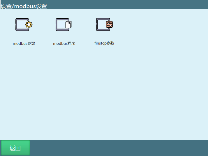
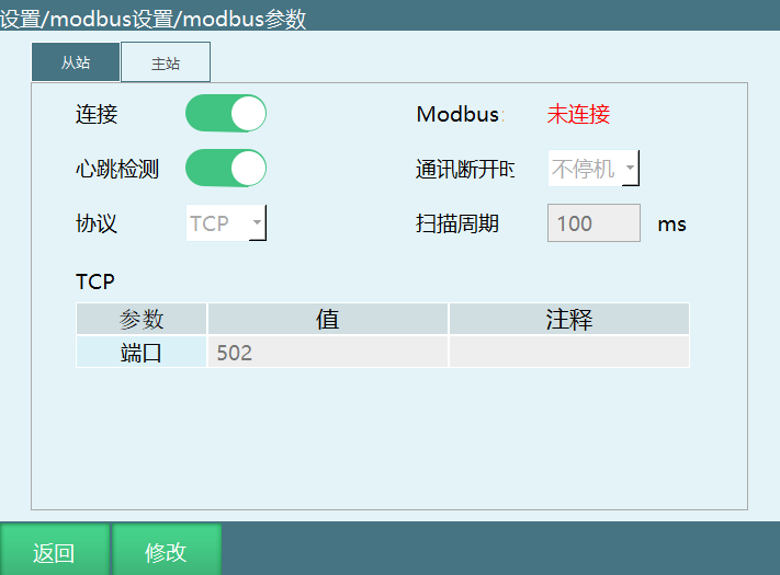
Parameters for switch detection and status display:
- Connection: The Modbus switch. After turning it on, Modbus signals are detected.
- Heartbeat detection: After turning it on, it is used to detect the send/receive frequency between Modbus and the controller. After the modbus connection is disconnected, the heartbeat detection displays that data sending/receiving is closed.
- Modbus: Displays the connection status between Modbus and the controller.
- Communication disconnected:
- No stop: When the Modbus slave is disconnected or the communication is disconnected, operation is not stopped and power is not turned off.
- Stop: When the Modbus slave is disconnected or the communication is disconnected, operation is stopped or power is turned off.
- Protocol: Select the currently set communication protocol; TCP/RTU can be selected.
- Scan period: The time required to perform one scan operation.
5.2 Setting Description
On this screen, you can set whether Modbus connects, the protocol used for the Modbus connection, whether this controller is the Modbus master/slave, and the various parameters when connected.
This unit as master:
- TCP (port): The connection port of the slave;
- RTU (port): The port of the slave's Modbus connection;
- RTU (ID): The ID of the slave;
- RTU (baud rate): The Modbus baud rate, needs to be set.
This unit as slave:
- TCP (port): The port used by this unit for connection, needs to be set;
- RTU (ID): The ID used by this unit for connection, needs to be set;
- RTU (port): The port used by this unit for connection, needs to be set;
- RTU (baud rate): The baud rate used by this unit for connection, needs to be set.
6 Communication Methods
6.1 Point Sending Description
Due to address code limits, too many points need to be sent in batches, with a maximum of 30 points per send.
As long as the controller is connected to the PLC, points can be sent, and the controller stores them automatically.
| Purpose | Address code | Process |
|---|---|---|
| All points send flag | 1001 | When the PLC needs to send points, set it to 1; set it to 2 when sending the last batch of points; the controller sets it to 0 after receiving all |
| Send-once send flag | 1002 | When the PLC needs to send points, set it to 1; after the controller finishes receiving, set it to 0; the PLC sets it to 1 again for the next sending process |
| Number of points in one send | 1003 | The number of points sent by the PLC at one time, up to 30 |
| Data stored for points | According to the count | Detailed below |
| Frame number of each data frame | 1004 | The frame number must be changed for each point sending, and cannot be the same as the last time |
| Clear controller point queue flag | 1005 | To discard the point queue already sent to the controller, the PLC sets it to 1, and the controller sets it to 0 after clearing |
6.2 Point Storage Data Description
One point data contains 1 coordinate system and the values of 6 axes (for a four-axis robot, it contains 1 coordinate system and the values of four axes).
| The i-th point | Address code | Comment |
|---|---|---|
| Coordinate system | 1010+20*(i-1) | 1≤i≤32 |
| Whether used | 1011+20*(i-1) | 1≤i≤32; send 0 to use, send 1 to not use |
| Value of the j-th axis | 1010+2+20*(i-1)+2*(j-1) | 1≤i≤32, 1≤j≤9. The axis value uses the float type, so it occupies 2 addresses |
Example: 88 points need to be sent. Since only 32 can be sent at a time, they need to be sent in 3 batches, with counts of 32, 32 and 24 respectively.
Process:
- The PLC sets 1003 to 32, sets the values of the various address codes used for point storage data, sets 1001 to 1, and sets 1002 to 1;
- The controller detects that 1002 is 1 and 1001 is 1, takes out the data of the point storage address codes according to the value of 1003, and then sets 1002 to 0;
- The PLC detects that 1002 is 0, sets 1003 to 32, sets the data of the point storage address codes, and then sets 1002 to 1;
- The controller detects that the value of 1002 is 1 and 1001 is 1, takes out the data of the point storage address codes according to the value of 1003, and then sets 1002 to 0;
- The PLC detects that the value of 1002 is 0, sets 1003 to 24, sets the data of the point storage address codes, sets 1001 to 2, and sets 1002 to 1;
- The controller determines that 1002 is 1 and 1001 is 2, takes out the data of the point storage address codes according to the value of 1003, then sets the value of 1002 to 0, and then sets 1001 to 0.
6.3 Instructions
MOVCOMM - External Points: This instruction is used to move the points stored in the controller according to the set interpolation method.
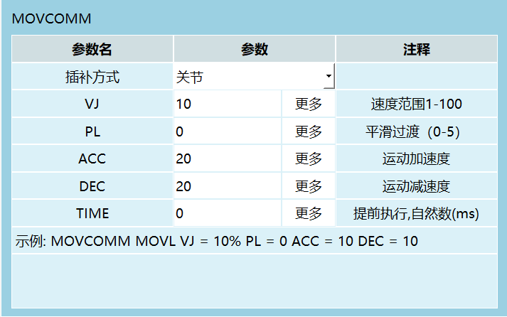
Parameter description:
| Parameter name | Parameter | Comment |
|---|---|---|
| Interpolation method | Joint/VJ | 10% (speed range 1-100) |
| Speed range | PL | 0 (smoothing transition 0-5) |
| Acceleration | ACC | 20 (motion acceleration) |
| Deceleration | DEC | 20 (motion deceleration) |
| Advance execution | TIME | 0 (natural number ms) |
Example: MOVCOMM MOVL VJ= 10% PL= 0 ACC= 10 DEC= 10
Detailed parameter description:
Interpolation method:
- a. Joint;
- b. Linear;
- c. Curve.
The interpolation method during motion; all points move with this interpolation method.
Speed: 1-100 when the interpolation method is joint. 2-1000 for other interpolation methods. The maximum speed during motion.
Smoothing (PL): 0-5. Can be filled with 0 when the interpolation method is curve, for smooth transition.
Acceleration: The maximum acceleration during operation.
Deceleration: The maximum deceleration during operation.
Time: The advance execution time; the next advance-executable instruction can be executed in advance.
Parameter source: Can be customized or bound to variables.
FAQ
Q1: How do I establish a TCP connection?
A: Ensure the controller and external device are on the same subnet (such as 192.168.1.xxx), configure the IP and port, and turn on the connection switch on the "Settings - TCP Communication Settings" screen.
Q2: What are the format requirements when the SENDMSG instruction sends variables?
A: Add the $ symbol before the variable. For example, to send the value of variable D001, write $D001. Strings and variables can be sent in a mixed manner.
Q3: How does the PARSEMSG instruction parse received data?
A: The first variable must be set, and the data is stored sequentially in consecutive variable addresses. It can be set whether to clear the cache after parsing.
Q4: How do I configure the data upload function?
A: In "Settings - Data Upload", configure the FTP server parameters (IP, port, username, password, path), set the data collection and upload periods, and configure the data format strings.
Q5: How are large numbers of points handled during external point transmission?
A: A maximum of 30 points can be sent at a time, so they need to be sent in batches. Use address codes 1001-1005 to control the sending process, and wait for the controller to finish processing after each send before sending the next batch.
Q6: What two modes does Modbus communication have?
A: It supports two protocols: TCP and RTU. TCP is based on Ethernet, and RTU is based on serial communication, requiring parameters such as the baud rate to be set.
Q7: What value does the MSG_CONN_ST instruction return?
A: It returns 1 when the communication is normal and 0 when the communication fails, and the result is stored in the specified BOOL variable.
Q8: What file formats are supported for data upload?
A: Two formats are supported: CSV and TXT. The CSV format is more convenient for data statistics and analysis.