Modbus Multi-Master Connection
Function Introduction
The Modbus multi-master connection function allows multiple master devices to connect to the controller simultaneously, enabling collaborative control of the robot. The controller acts as a slave and supports up to 9 master devices connecting simultaneously, including Modbus Poll software, touch screens, etc.
Environment Requirements
Hardware Equipment:
- Controller (supports Modbus function)
- Computer (with Modbus Poll software installed)
- Touch screen (supports Modbus protocol)
- Switch (for connecting controller, computer and touch screen)
- Ethernet cable
Software Requirements:
- Modbus Poll software (for testing multi-master connections)
- Controller firmware (supports Modbus multi-master function)
Setting Location
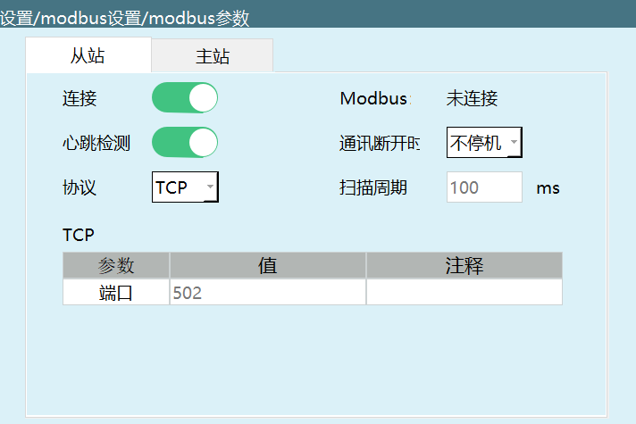
On the teach pendant: Settings -> Modbus Settings -> Modbus Parameters
Connection Steps
Hardware Connection:
- Connect the computer and touch screen to the controller through a switch
- Ensure all devices are on the same network subnet
Controller Settings:
- In the Modbus Parameters interface, select protocol as TCP
- Set the controller as slave
- Turn on the connection enable switch
- Record the controller's IP address and port number
Modbus Poll Connection:
- Open Modbus Poll software
- Click Connection -> Connect
- Connection type: select ModbusTCP/IP
- Enter the controller's IP address and port number
- Set the scan cycle to be consistent with the teach pendant
- Click OK to complete the connection
Touch Screen Connection:
- Configure the Modbus TCP connection on the touch screen
- Enter the controller's IP address and port number
- Save the configuration and establish the connection
Multi-Master Control
- Maximum 9 masters supported: Multiple Modbus Poll instances and touch screens can connect simultaneously
- Parallel control: Different masters can send commands to the controller simultaneously
- IP address management: Ensure all master device IP addresses do not conflict
- Scan cycle: The scan cycles of all masters should be set reasonably to avoid network congestion
Notes
- Network Configuration: Ensure all devices are on the same network subnet and IP addresses do not conflict
- Scan Cycle: Set a reasonable scan cycle to avoid network congestion
- Connection Quantity: Maximum 9 masters can connect simultaneously. Exceeding this may cause connection failure
- Priority: When multiple masters send commands simultaneously, the controller processes them in the order received
- Communication Stability: Ensure the network connection is stable to avoid disconnections
FAQ
Q1: Why can't a multi-master connection be established?
A1: Check the following:
- Ensure the controller's Modbus connection enable switch is turned on
- Verify all devices are on the same network subnet
- Check if IP addresses conflict
- Confirm the port number is set correctly
- Check if the network connection is stable
Q2: What to do when multi-master connection response is slow?
A2: Possible causes and solutions:
- Reduce the number of simultaneously connected masters
- Increase the scan cycle to reduce communication frequency
- Check if network bandwidth is sufficient
- Ensure controller performance meets multi-master requirements
Q3: What to do when data conflicts occur during multi-master connection?
A3: Suggestions:
- Reasonably distribute the control range of different masters
- Avoid multiple masters simultaneously modifying the same parameters
- Consider multi-master collaborative logic in control system design
Q4: How to test if multi-master connection is normal?
A4: The following methods can be used to test:
- Write different address codes in different Modbus Poll instances
- Operate the robot on the touch screen
- Observe whether the controller can correctly respond to all master commands
- Check if the communication status is stable