1 Safety Instructions
Warning:
• This manual involves operations on robot parameters, external axis parameters, and system settings. • The system must only be used after carefully reading and fully understanding the manual instructions. • Any content not described in this manual should be considered "not allowed" or "prohibited".
Note:
• Diagrams drawn in this manual are for illustrative purposes only. The complete equipment must be installed before using this system. • Due to system functional improvements, the manual may be appropriately modified, and the manual version number will be updated accordingly.
> 1.1 Safety Notice Levels
This manual includes safety precautions to ensure operator safety and prevent equipment damage. These are described in the text as "Warning" and "Note" according to their importance in terms of safety. Supplementary explanations are described as "Remarks". Users must familiarize themselves with the items described in these "Warnings", "Notes", and "Remarks" before use.
Warning:
• Used when incorrect operation may result in death or serious injury to the user.
Note:
• Used when incorrect operation may result in minor or moderate injury to personnel, or damage to property.
Remarks:
• Used to describe supplementary information other than warnings or notes.
2 Robot and External Axis Parameters
Navigation Path: Settings → Robot Parameters
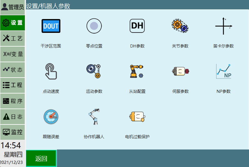
The Robot Parameters interface contains the following functional modules:
- Slave Configuration
- DH Parameters
- Joint Parameters
- Zero Position
- Cartesian Parameters
- Interference Zone Range
- Jog Speed
- Motion Parameters
- Servo Parameters
- Following Error
- Collaborative Robot
> 2.1 Robot Parameters
In the DH Parameters interface, we provide a preset robot function. If the dropdown list contains the robot model you are using, you can quickly and conveniently set up the robot's various parameters through this function.
Operating Steps:
- Click [Preset Robot] in the upper-left corner of the DH Parameters interface to select a pre-configured robot model. After selection, the robot's DH parameters and joint parameters will be automatically filled in.

- After selecting a preset robot, the zero point needs to be manually modified.
Remarks:
• For the preset robot configuration method, please contact the system manufacturer.
2.1.1 Slave Configuration
Warning:
• Do not perform operations such as servo ready, power on, or run without configuring this parameter.
To modify robot settings, go to [Settings] - [Robot Parameters] - [Slave Configuration].
Related Steps:
Enter the [Settings] - [Robot Parameters] - [Slave Configuration] interface
This interface displays the names and number of slave stations currently connected to the controller; you can modify the communication cycle and bus type. Bus types include EtherCAT and CANopen. Changes take effect after restart.
When the bus type is EtherCAT:
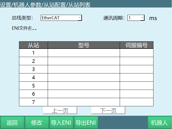
| Parameter | Description |
|---|---|
| Bus Type | EtherCAT or CANopen |
| Communication Cycle | Options: 1ms, 2ms, 4ms, 8ms |
| ENI File Name | EtherCAT network configuration file |
| Slave List | Displays the model and number of currently connected servo slaves |
| Import ENI / Export ENI | Import or export the EtherCAT network configuration file |
When the bus type is CANopen:
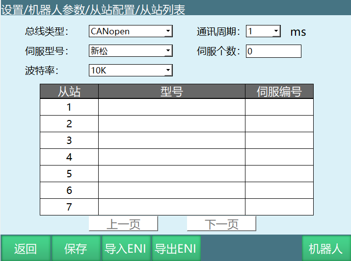
| Parameter | Description |
|---|---|
| Bus Type | EtherCAT or CANopen |
| Communication Cycle | Selectable values |
| Servo Model | e.g. Siasun, etc. |
| Servo Count | Number of configured servos |
| Baud Rate | e.g. 10K, 100K, 500K, 1M |
| Slave List | Displays the model and number of currently connected servo slaves |
Robot Configuration Interface:
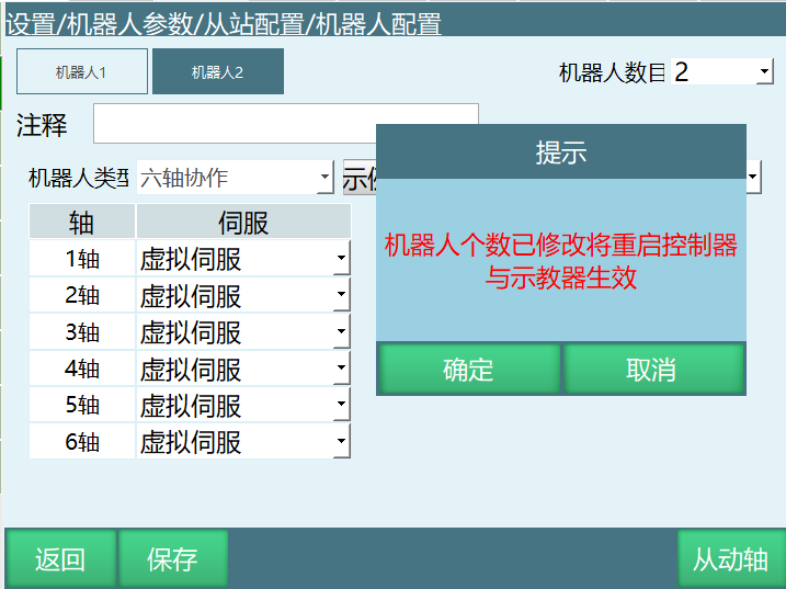
Click [Robot] to enter the [Robot Configuration] interface, where you can set the number of robots, robot type, servo, number of external axis groups, and external axis type.
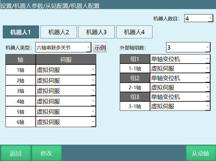
Parameter Description:
| Parameter | Description |
|---|---|
| Number of Robots | One controller supports up to 4 robots. A prompt will appear after modification indicating that a restart is required for changes to take effect |
| Robot Type | Six-axis serial-CBBBCA, Six-axis serial-CCBABC, Six-axis serial-CBBBAC, Six-axis serial-CBBBCA, Six-axis serial-CCBABC, Five-axis serial-CBBAB, Four-axis serial-CCZC, Four-axis serial-ZCCC, Four-axis serial-CBBC, Four-axis serial-CZXC, Four-axis serial-CBBB, Four-axis serial-XYZC, Three-axis serial-CCZ, Three-axis serial-XYZ, Five-axis serial-XYZAB, Five-axis serial-XYZAC, Two-axis serial-CC, Four-axis Cartesian-XCCZ, Six-axis serial-XYZCAC, Five-axis hybrid robot, Four-axis serial-XCZC, Six-axis serial-CBBCBA, Three-axis serial-CCA, Delta parallel robot, etc. Parameters will be reset after changing the robot type — change with caution! |
| Number of External Axis Groups | External axis types support ground rail, single-axis/dual-axis positioner. Up to 3 external axis groups supported, maximum total axes is 5, and only one ground rail is allowed |
| Servo | Servo sequence number and model. With the added servo file function, users can configure themselves |
Currently Supported IO Types:
| IO Board Manufacturer | IO Model |
|---|---|
| Huatai | Huatai |
| Huatai PWM | |
| Mengtong | Mengtong |
| Mengtong Old | |
| Chengshi | Chengshi |
| Taibang | Taibang |
| INEXBOT | R1 |
| R1_PWM | |
| R2 | |
| R2A | |
| R2B | |
| R3 | |
| R4 | |
| R4P | |
| High-Precision Clock | |
| Xiling | Xiling EJ1861 |
| Xiling EJ1862 | |
| Motong | Motong |
| Leisai | Leisai |
| Yanwei | Yanwei CATIOA |
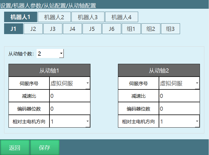
Slave Axis Interface:
This interface allows you to set the number of slave axes, servo, gear ratio, encoder bits, and direction relative to the main motor.
Parameter Description:
| Parameter | Description |
|---|---|
| Number of Slave Axes | Number of slave axes |
| Servo Number | Servo number corresponding to the slave axis |
| Gear Ratio | Gear ratio of the slave axis |
| Encoder Bits | Number of encoder bits for the slave axis |
| Direction Relative to Main Motor | Rotation direction of the slave axis relative to the main motor |
2.1.2 Joint Parameter Settings
Warning:
• Do not perform operations such as servo ready, power on, or run without configuring this parameter.
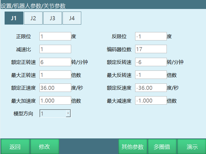
To set joint parameters, go to [Settings] - [Robot Parameters] - [Joint Parameters].
Related Steps:
Enter the [Settings] - [Robot Parameters] - [Joint Parameters] interface
The input fields are grayed out and values cannot be entered
Click Modify; the Modify button changes to Save, and the input fields turn white, allowing parameter modification
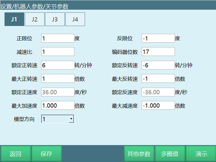
- Click Save to confirm the modification
Parameter Descriptions:
| Parameter | Description | Unit |
|---|---|---|
| Positive Limit | Maximum range of the robot joint in the positive direction | degrees |
| Negative Limit | Maximum range of the robot joint in the negative direction (must be a negative value) | degrees |
| Gear Ratio | Gear ratio of the reducer | - |
| Encoder Bits | Number of encoder bits | - |
| Rated Positive Speed | Rated motor speed in the positive direction | rpm |
| Rated Negative Speed | Rated motor speed in the negative direction (must be a negative value) | rpm |
| Maximum Positive Speed | Maximum motor speed in the positive direction, expressed as a multiple of the rated positive speed. E.g. if rated positive speed is 3000 rpm and maximum positive speed is 6000 rpm, enter 2x | multiplier |
| Maximum Negative Speed | Maximum motor speed in the negative direction, expressed as a multiple of the rated negative speed. E.g. if rated negative speed is -4000 rpm and maximum negative speed is -6000 rpm, enter -1.5x (must be a negative value) | multiplier |
| Rated Positive Velocity | Rated positive velocity of the robot joint, automatically calculated from rated positive speed, encoder bits, and gear ratio (for 4-axis SCARA axis 3 and 4-axis SCARA special axis 1, the lead screw pitch is also included). No manual entry required | °/s |
| Rated Negative Velocity | Rated negative velocity of the robot joint, automatically calculated from rated negative speed, encoder bits, and gear ratio. No manual entry required (must be a negative value) | °/s |
| Maximum Acceleration | Maximum acceleration of robot joint motion, expressed as a multiple of the rated positive velocity. E.g. if rated positive velocity is 300°/s and maximum acceleration is 1500°/s², enter 5x | multiplier |
| Maximum Deceleration | Maximum deceleration of robot joint motion, expressed as a multiple of the rated negative velocity. E.g. if rated negative velocity is 300°/s and maximum deceleration is 1200°/s², enter -4x. It is recommended that maximum acceleration and maximum deceleration values be the same (must be a negative value) | multiplier |
| Model Direction | Model direction can be set by referring to the joint positive direction diagram in the Zero Position interface. The "+" jog key for each axis should match the direction shown in the joint positive direction diagram. Select 1 if the same, -1 if opposite | - |
| Gear Backlash | Whenever the joint moves in the opposite direction, compensation is applied by the entered angle value. This parameter is in [Settings] - [Robot Parameters] - [Joint Parameters] - [Other Parameters] | degrees |
Joint Positive Direction Diagram:
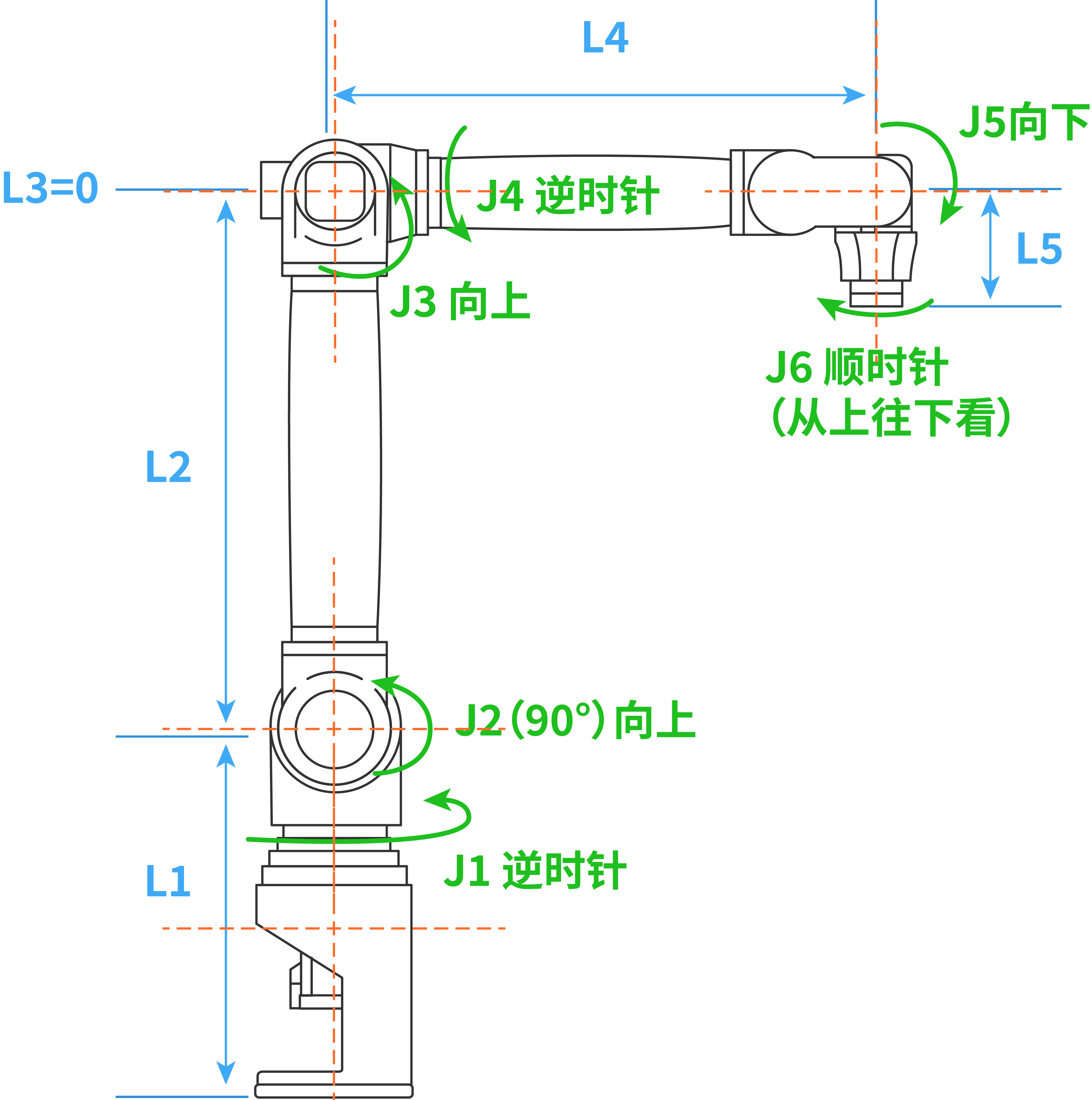
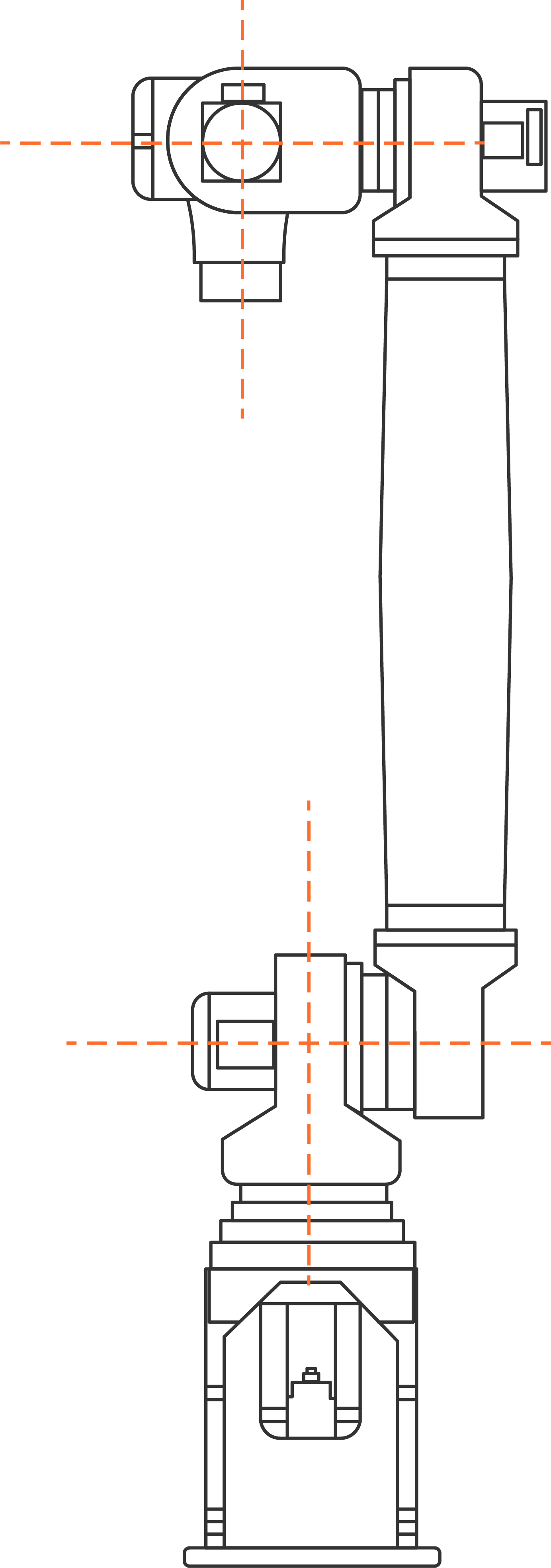
| Robot Type | Axis Positive Direction | Positive Direction (Top View or Left View) |
|---|---|---|
| Six-axis | J1+ | Counterclockwise |
| J2+ | Upward | |
| J3+ | Upward | |
| J4+ | Counterclockwise | |
| J5+ | Downward | |
| J6+ | Clockwise | |
| Four-axis SCARA | J1+ | Counterclockwise |
| J2+ | Counterclockwise | |
| J3+ | Upward | |
| J4+ | Clockwise | |
| Four-axis palletizing | J1+ | Counterclockwise |
| J2+ | Upward | |
| J3+ | Upward | |
| J4+ | Counterclockwise | |
| Four-axis joint | J1+ | Counterclockwise |
| J2+ | Upward | |
| J3+ | Upward | |
| J4+ | Upward | |
| Five-axis joint | J1+ | Counterclockwise |
| J2+ | Upward | |
| J3+ | Upward | |
| J4+ | Counterclockwise | |
| J5+ | Downward | |
| Two-axis SCARA | J1+ | Counterclockwise |
| J2+ | Counterclockwise | |
| Three-axis SCARA | J1+ | Counterclockwise |
| J2+ | Counterclockwise | |
| J3+ | Downward | |
| Single-axis | J1+ | Counterclockwise |
| Four-axis SCARA special | J1+ | Upward |
| J2+ | Counterclockwise | |
| J3+ | Counterclockwise | |
| J4+ | Clockwise |
2.1.2.1 Multi-Turn Value Overflow Count
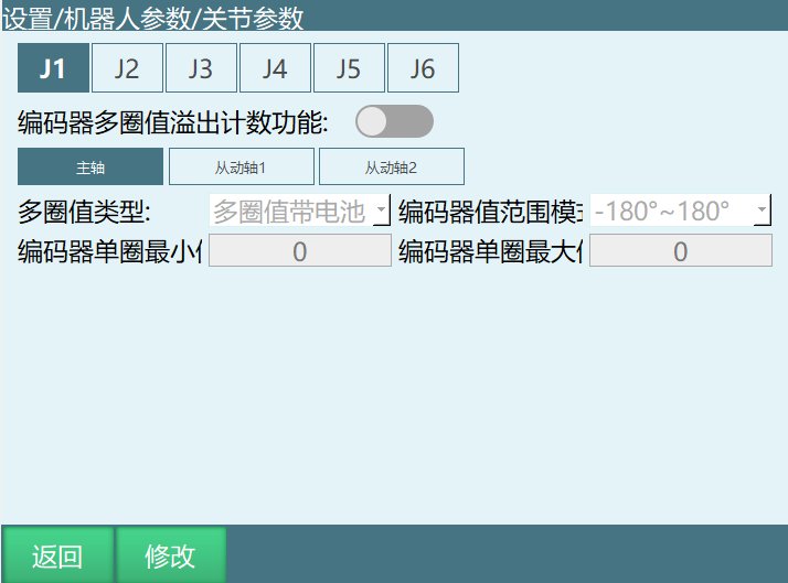
To configure multi-turn value overflow count, go to [Settings] - [Robot Parameters] - [Joint Parameters], click [Multi-Turn Value], and modify the encoder range.
Function Description: This function eliminates the effects caused by jumping between the encoder's maximum/minimum values.
Principle: For example, if the encoder multi-turn value range is [-2147483648, 2147483647] and the current encoder multi-turn position is 2147483647, then rotating one more unit in the positive direction results in -2147483648. If the system does not know the encoder multi-turn value range, it will perceive a sudden jump in the robot's position rather than recognizing that it only moved one unit, which can easily lead to a runaway condition.
Warning:
• This parameter must be filled in. Failure to do so may result in the following issues: ① Significant jumps in position, e.g. suddenly changing from 4 degrees to 40 degrees. ② Runaway motion. • If slave axes are configured, the encoder maximum/minimum values for the slave axes must also be filled in.
Parameter Description:
| Parameter | Description |
|---|---|
| Encoder Multi-Turn Value Overflow Count Function | Enable the button to use this function for the joint |
| Multi-Turn Value Type | Multi-turn with battery, multi-turn without battery, single-turn |
| Encoder Value Range Mode | 0°~360° or -180°~180° |
| Encoder Single-Turn Minimum | Fill in according to the calculation method |
| Encoder Single-Turn Maximum | Fill in according to the calculation method |
Multi-Turn Value Type Description:
• Multi-turn with battery: Range is 0 to (2^32)-1 (encoder value range mode 0~360), or -(2^(32-1)) to (2^(32-1))-1 (encoder value range mode -180~180).
• Single-turn: Range is 0 to (2^X)-1 (encoder value range mode 0~360), -(2^(X-1)) to (2^(X-1))-1 (encoder value range mode -180~180), where X is the encoder bit count.
• Multi-turn without battery: Although multi-turn without battery encoders behave the same as multi-turn with battery when the robot is powered on, the multi-turn value disappears after a power cycle, leaving only the single-turn value. Therefore, we need to treat it as a single-turn type and set the encoder range accordingly. When powered on, the number of turns exceeding the single-turn range is recorded each time the encoder is read/written, and saved to a file for use after power-off restart. After power-off restart, the recorded excess turn count is read to restore the actual robot position.
Encoder Value Range Mode: 0°~360° or -180°~180°.
Encoder Single-Turn Minimum & Encoder Single-Turn Maximum: Calculate and fill in according to the above method. For example, if the encoder type is multi-turn without battery, encoder bits are 17, encoder value range mode is 0~360, then single-turn minimum is 0, single-turn maximum is (2^17)-1 = 131071.
2.1.3 Robot Zero Position
Warning:
• After modifying the zero position, all job programs become invalid and must not be used. • Zero-point calibration requires correct slave configuration and joint parameter configuration.
2.1.4 Zero-Point Calibration
If the robot's zero position is a non-standard zero position, the user can align the robot according to its alignment holes and then set the current robot position coordinates as the zero position in the Robot Zero Position interface.
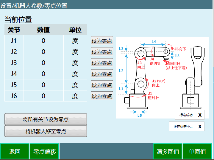
Detailed Operating Steps:
Open the [Settings] - [Robot Parameters] - [Zero Position] interface
In "Joint Coordinate Mode", the robot posture when each joint is at zero position is shown in the figure below, where the lower arm is vertical, the forearm is horizontal, and the wrist (5th joint) is also horizontal. Generally, the robot body design already includes zero-position interfaces (e.g. grooves, marks, scales, etc.)
Click the [Set as Zero] button corresponding to the axis you want to set as zero, or click [Set All Joints as Zero] to set all joint coordinates to zero at once
In the confirmation prompt that appears, click [OK] to proceed with the robot zero-point setting
Zero position setting for the axis (all axes) is successful: • In servo-ready state, press the DeadMan key, then press [Move Robot to Zero] to ensure robot safety • Speed value is automatically adjusted to 5% for operation; you can manually increase the motion speed • After setting the current position as zero, the current position axis coordinates become (0,0,0,0,0,0) • You can set one or more axes' current position coordinates as zero coordinates; the unset axes retain their original zero coordinates
Warning:
• Without home position calibration, teach and playback operations cannot be performed. • In systems using multiple robots, each robot must have its home position calibrated. • When coupling relationships exist between joint axes (e.g. the common coupling between axis 5 and axis 6), axis 5 must be at its zero position for axis 6's recorded zero data to be valid. Otherwise, axis 6's zero data is invalid. Therefore, axis 6's zero data must be recorded while axis 5 is at its zero position. If no coupling relationship exists, each axis can be independently calibrated, and one axis's zero position will not affect other joints' zero positions.
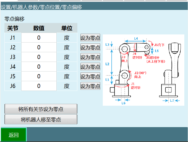
2.1.5 Zero Offset
Zero offset can be used when the user needs to adjust the zero point. Manual values can be entered, and the operation method is similar to zero-point calibration.
2.1.6 Clear Multi-Turn Values
Warning:
• Proceed with extreme caution. This operation will clear the robot encoder values, causing the factory-saved zero data to be cleared. • This may result in the following issues: ⅰ. Robot loses accuracy; ⅱ. Robot cannot operate normally; ⅲ. Previously established positions cannot be reached.
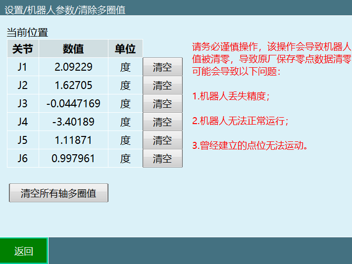
Operation Description:
• Clear All Axis Multi-Turn Values: Clears the multi-turn values of all axes of the robot at once (excluding external axes) • Clear After Each Joint: Clears the multi-turn value of that axis
2.1.7 Single-Turn Values
This function allows you to modify the single-turn value for each axis.
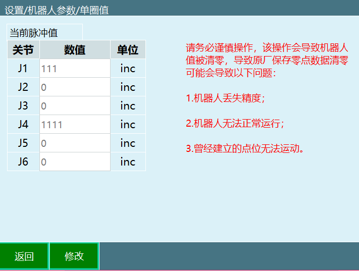
Warning:
• Proceed with extreme caution. This operation will clear the robot encoder values, causing the factory-saved zero data to be cleared. • This may result in the following issues: ⅰ. Robot loses accuracy; ⅱ. Robot cannot operate normally; ⅲ. Previously established positions cannot be reached.
2.1.8 Zero Loss Recovery Method
Prerequisites:
The robot lost its zero point only due to operational error (not from a collision)
The single-turn values before zero loss were recorded (when multi-turn values have not been cleared, the values shown in the single-turn interface are from the last zero-point calibration)
Operating Steps:
Locate the recorded single-turn values from before the zero loss
Teach the robot to the mechanical zero position
Clear multi-turn values for all robot axes (this operation clears both multi-turn and single-turn values — proceed with caution)
Calibrate zero points for all robot axes
Enter the single-turn value data prepared in step 1 in the single-turn interface
Operate the robot to return to zero
Confirm whether the zero point is correct
2.1.9 DH Parameters
Warning:
• Do not perform operations such as servo ready, power on, or run without configuring this parameter • Zero-point calibration must be configured before configuring DH parameters
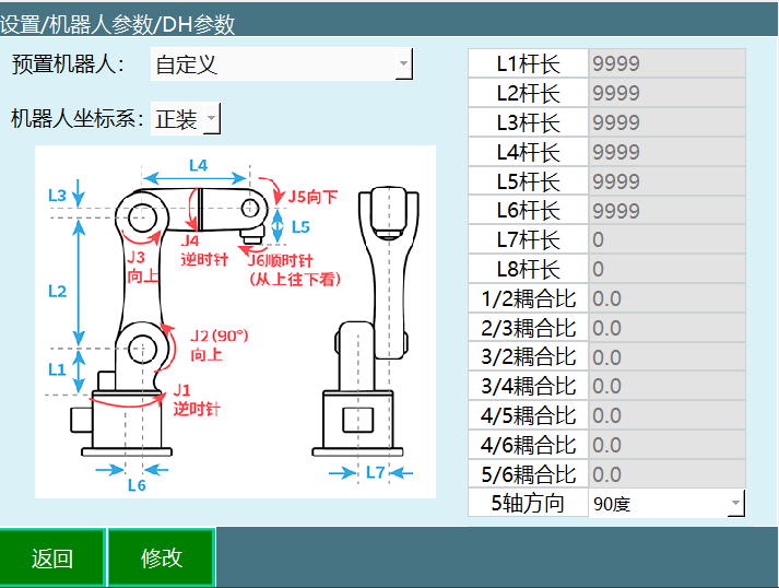
Related Steps:
Enter the [Settings] - [Robot Parameters] - [DH Parameters] interface
Click the [Modify] button at the bottom
Fill in according to your actual robot specifications
Click the parameter value you want to modify (e.g. L2); a soft keyboard will appear. Enter the replacement number and click Confirm
Click the [Save] button to complete the parameter modification
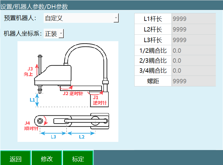
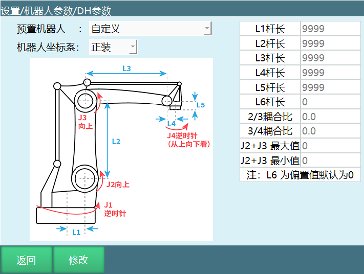
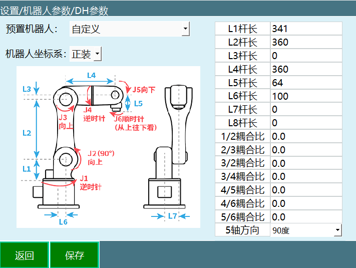
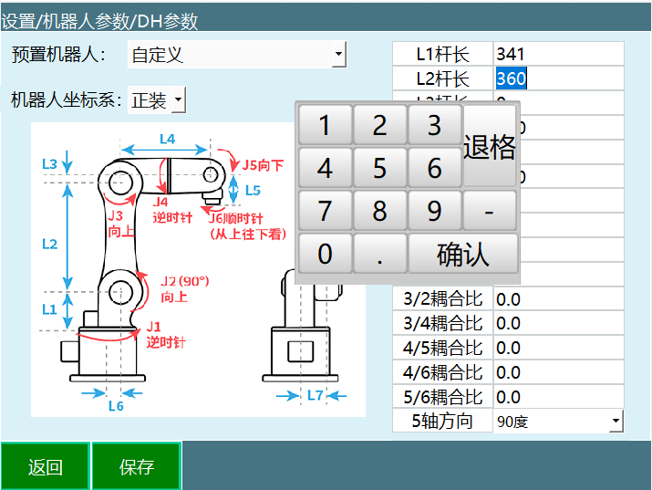
Parameter Descriptions:
| Parameter | Description | Unit |
|---|---|---|
| Preset Robot | By pre-importing robot joint parameters and DH parameters into the controller, the steps of repeatedly filling in parameters can be saved. For specific usage, please contact the manufacturer | - |
| Robot Coordinate System | Upright or inverted | - |
| Link Length | Robot dimensions. L1-L6 are the link lengths of each joint, L7-L8 are offset values | mm |
| Coupling Ratio | Some robot body designs cause the motor to span multiple axes to drive a certain axis, resulting in coupling between two axes | - |
| 1/2 Coupling Ratio | Angle ratio of axis 2 following axis 1 rotation | - |
| 2/3 Coupling Ratio | Angle ratio of axis 3 following axis 2 rotation | - |
| 3/2 Coupling Ratio | Angle ratio of axis 2 following axis 3 rotation | - |
| 3/4 Coupling Ratio | Angle ratio of axis 4 following axis 3 rotation | - |
| 4/5 Coupling Ratio | Angle ratio of axis 5 following axis 4 rotation | - |
| 4/6 Coupling Ratio | Angle ratio of axis 6 following axis 4 rotation | - |
| 5/6 Coupling Ratio | Angle ratio of axis 6 following axis 5 rotation | - |
| Axis 5 Direction | Axis 5 direction during zero-point calibration. 90° indicates vertical direction, 0° indicates horizontal direction | degrees |
| Pitch | Pitch of the vertical-motion link in 4-axis SCARA (axis 3 for 4-axis SCARA, axis 1 for 4-axis SCARA special) | mm |
| J2+J3 Minimum/Maximum | Parameters for 4-axis palletizing robots | degrees |
Coupling Ratio Formula:
Following Axis Rotation Angle
Coupling Ratio = ───────────────────
Main Axis Rotation AngleExample: For instance, if we rotate axis 2 by 10° and find that axis 3 follows by 15°, the coupling ratio is:
15°
Coupling Ratio = ──── = 1.5
10°
Axis 5 Direction Description:
• 3: Horizontal direction • 1: Vertical direction
J2+J3 Minimum/Maximum Description: Move axes 2 and 3 of the 4-axis palletizing robot to J2max/J3max, J2min/J3max, J2max/J3min, J2min/J3min respectively, record the J2+J3 values for all four cases, remove the highest and lowest values, and the remaining two are the J2+J3 minimum/maximum.