Conveyor Tracking Process Manual
Process Introduction
Conveyor tracking refers to the robot using the user-input material point position and the corresponding encoder value at that position to calculate the material point position in real time, and tracking the material through motion.
Click [Process] - [Conveyor Tracking Process] - [Parameter Settings] to enter the conveyor tracking process parameter settings interface.
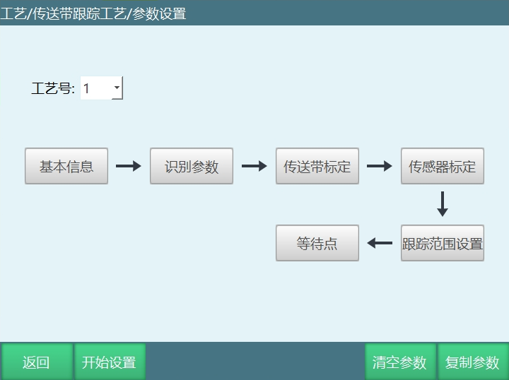
Clear Parameters: Clear the parameters of the currently selected process number.
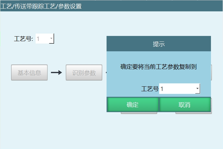
Copy Parameters: Copy all parameters of this process number to another process number.
Basic Information
Before setting all parameters, select a process number in the "Parameter Settings" interface. Each process number saves all parameters. This basic information provides basic settings for conveyor parameters.
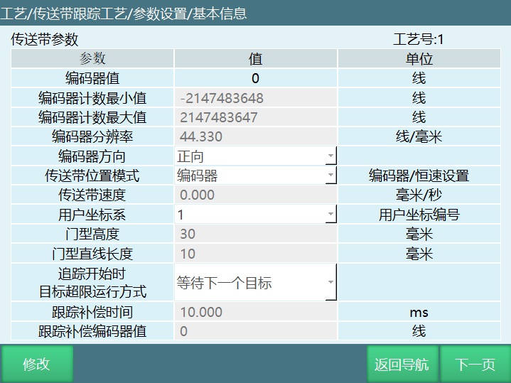
- Encoder Value
After the encoder is connected, the current connected encoder value is automatically recognized. This value is read-only and cannot be modified.
When the encoder value cannot be read successfully, there are generally two situations: incorrect wiring of the encoder interface; incorrect port position on the IO board for the encoder connection.
The port position on the IO board can be referenced from the corresponding IO board definition diagram; the encoder port wiring method can be referenced from the corresponding encoder definition diagram.
- Encoder Count Maximum/Minimum:
The maximum count value of the encoder data processing module depends on the IO board used as the encoder data processing module. The current ranges are:
Drive-control integrated version: 0-65535;
Nuodajia firmware below version 18: 0-1024
Nuodajia firmware version 18: -2147483648 to 2147483647;
R4C version: -2147483648 to 2147483647.
- Encoder Resolution:
The unit pulse emitted by the encoder when the conveyor moves 1mm. This value is the calibration result.
- Encoder Direction:
Turn on the conveyor and observe whether the offset and speed increase with conveyor movement. If there is no change, the encoder type or resolution settings do not match actual conditions. If it decreases with conveyor movement, select direction here.
- Conveyor Position Mode:
Select Encoder: Normal sensor calibration.
Select Constant Speed Setting: When constant speed is set, it is independent of the encoder. Conveyor speed can be manually entered for setting (after manually modifying speed, recalibrate the sensor).
Note: When setting constant speed, sensor position calibration calculation has error. Error factor: the conveyor motion time interval recorded during calibration is too large.
Solution: Stop the robot tool on the workpiece following path. When the workpiece passes the tool, calibrate directly to reduce error.
- Conveyor Speed
The current conveyor speed, read-only.
- User Coordinate System
Calibrate this user coordinate system according to the actual conveyor motion direction. Tracking calculation and motion are performed in this user coordinate system.
Arch Height: The maximum Z-axis height when the robot moves in arch motion.
Arch Linear Length: When the robot lifts, Z must travel to the set length before moving X, Y coordinates (this value cannot exceed the arch height).
Note: This arch motion is used when the robot receives the pickup coordinate. The robot needs to move to the workpiece point and pick up in arch mode.
- Target Exceeding Limit Behavior When Tracking Starts
Wait for Next Target: When the workpiece exceeds the tracking range, the teach pendant lower right corner will prompt "Conveyor tracking currently exceeding limit, tracking next target".
Jump to Tracking End: When the workpiece exceeds the tracking range, the instruction will jump to the tracking end instruction position.
- Tracking Compensation Time
Used to solve the compensation lag problem; calculated through time and conveyor speed. Compensation lag is mainly caused by encoder data filtering and robot motion planning execution.
- Tracking Compensation Encoder Value
Used to solve the compensation lag problem; calculated through encoder value and resolution.
Parameter Identification
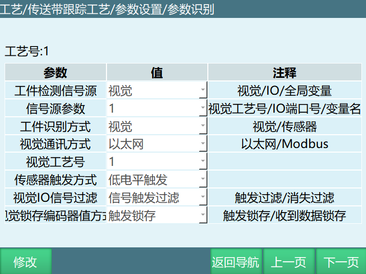
- Workpiece Detection Signal Source
Workpiece detection can be performed through vision, IO, or global variables.
- Signal Source Parameters
If detecting conveyor workpieces through IO, signal source parameters can select IO port number.
If detecting conveyor workpieces through global variables, signal source parameters can select global boolean variables.
- Workpiece Identification Method
Workpiece identification can be performed through vision or sensor. When selecting sensor, vision communication method does not need to be selected.
- Vision Communication Method
If identifying conveyor workpieces through vision, Ethernet or Modbus communication methods can be selected.
- Vision Process Number
Range 1-9
- Sensor Trigger Method
Only when the workpiece detection signal source is set to digital IO, signal source parameters select the corresponding IO port, and the workpiece identification method is sensor, the sensor trigger method can take effect. Trigger methods include high-level trigger (IO signal 1 triggers) and low-level trigger (IO signal 0 triggers).
- Vision IO Signal Filtering
- Vision Trigger Filtering:
When the first workpiece triggers the sensor signal, and when the second workpiece triggers the sensor signal, if vision still has not returned data, discard the first workpiece's sensor signal and record the second workpiece's sensor signal. The robot will not pick up the first workpiece.
When the first workpiece triggers the sensor signal, and when the second workpiece triggers the sensor signal, if vision returns data, the robot picks up normally.
- Signal Disappearance Filtering:
When the first workpiece triggers the sensor signal, and when the second workpiece trigger sensor signal disappears, if vision still has not returned data, discard the first workpiece's sensor signal and record the second workpiece's sensor signal. The robot will not pick up the first workpiece.
When the first workpiece triggers the sensor signal, and when the second workpiece trigger sensor signal disappears, if vision returns data, the robot picks up normally.
- Vision Latch Encoder Value Method: When the robot is running, using sensor and vision together to pick up workpieces. When a workpiece passes the sensor, vision takes a photo to calculate the workpiece position. During instruction execution, there are many uncertain factors and camera processing is slow, so the latch function exists.
Trigger Latch: Latch the current conveyor encoder value when vision triggers photo capture. Each time vision is triggered, if the previous workpiece's sensor trigger did not receive vision data, discard the previous latched conveyor encoder data.
Data Receipt Latch: Latch the encoder value when data is received from the camera.
Conveyor Calibration
The user coordinate system is selected in basic information. The user coordinate system needs to be calibrated by the user in advance.
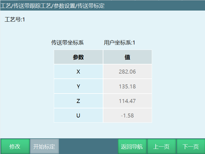
Conveyor calibration calculates the conveyor's user coordinate system by calibrating 3 workpiece position points. Click [Modify], [Start Calibration] button to enter the calibration interface.
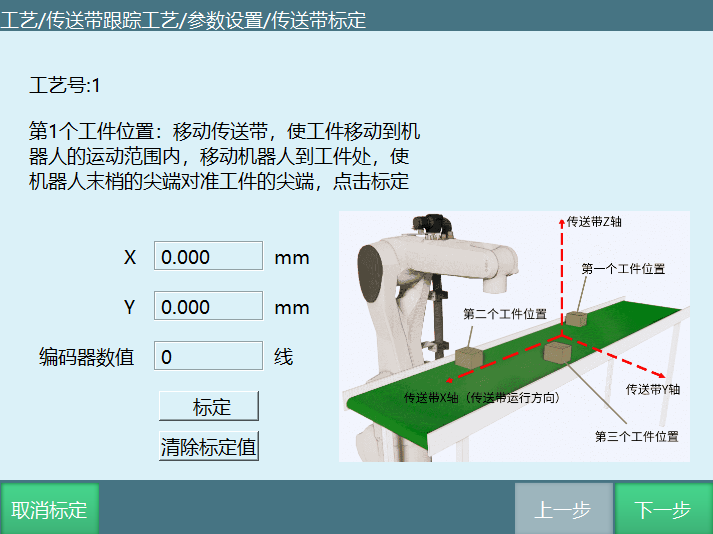
Step 1: Place a pointed calibration cone on the conveyor belt. Move the conveyor to bring the calibration cone into the robot's motion range. Turn off the conveyor. Move the robot to the workpiece, aligning the robot tool tip with the calibration cone tip. Click Calibrate.
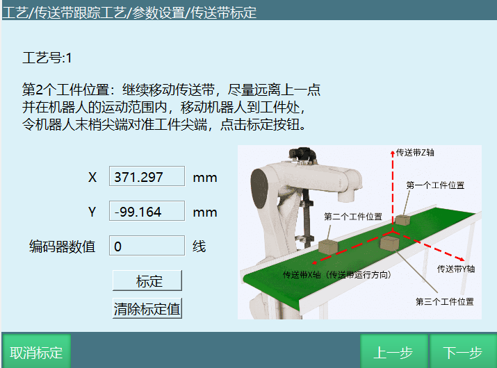
Step 2: Slightly teach and raise the robot. Continue moving the conveyor, trying to be as far from the previous point as possible while within the robot's motion range. Turn off the conveyor. Move the robot to the calibration cone, aligning the robot tool tip with the calibration cone tip. Click the Calibrate button.
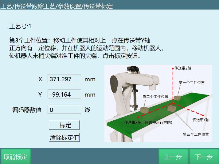
Step 3: Move the calibration cone to have a certain displacement relative to the previous point in the conveyor Y-axis positive direction, within the robot's motion range. Move the robot to the calibration cone, aligning the robot tool tip with the calibration cone tip. Click the Calibrate button.
Step 4: Raise the robot a certain distance, click the [Calculate] button. Calibration complete.
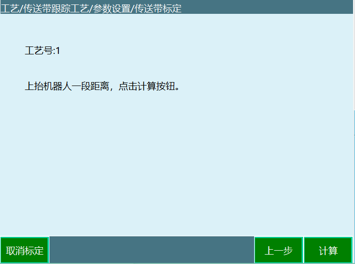
Note: The direction of the selected user coordinate system must be consistent with the conveyor calibration direction.
Sensor Calibration
When the workpiece identification method is set to sensor, the sensor needs to be calibrated on this interface. Click [Modify] - [Start Calibration] button to enter the calibration interface, as shown below.
Note: When using vision to identify workpieces, calibration is not needed. Skip directly.
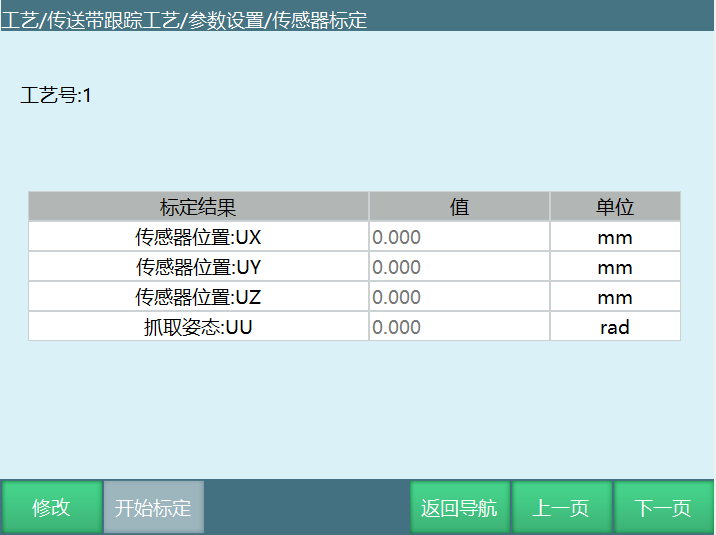
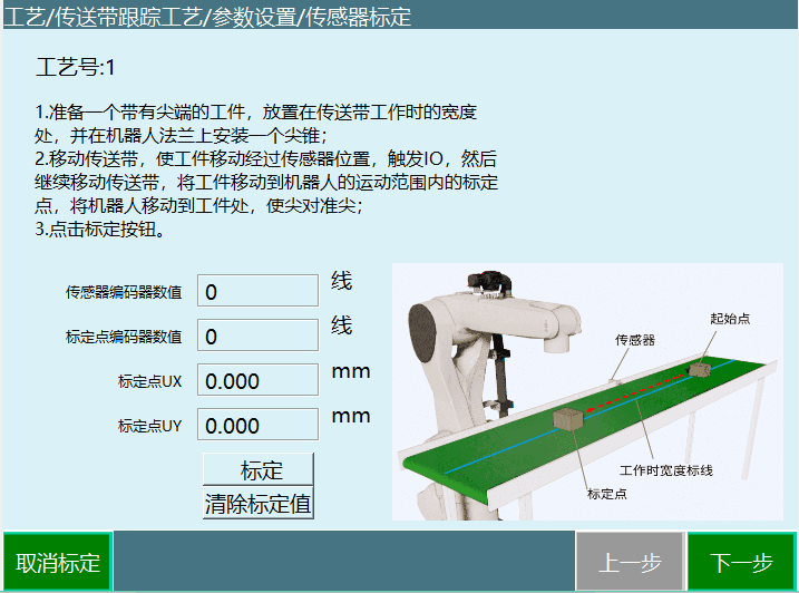
Step 1: Prepare a workpiece with a tip, place it at the conveyor belt's working width position, and install a pointed cone on the robot flange. Move the conveyor to bring the workpiece past the sensor position, triggering IO. Then continue moving the conveyor to bring the workpiece to the calibration point within the robot's motion range. Stop the conveyor. Move the robot to the workpiece, aligning tip to tip. Click the [Calibrate] button. As shown below:
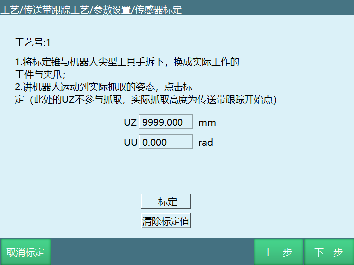
Step 2: Remove the calibration cone and robot pointed tool, replace with the actual working workpiece and gripper. Move the robot to the actual pickup height and posture. Click the [Calibrate] button. As shown below:
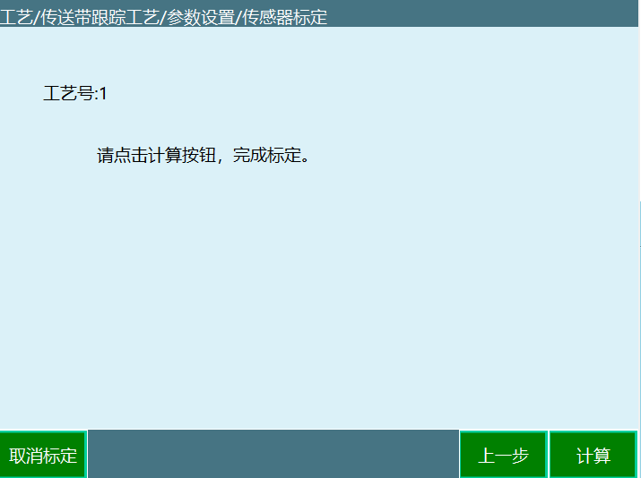
Step 3: Click the [Calculate] button. Calibration parameters are saved. See the figure below.
Tracking Range Settings
This interface is used to set some key positions and tracking ranges during the robot's tracking process, as shown below.
Note: Use the user coordinate system calibrated from conveyor calibration for calibration.
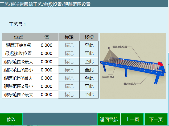
- Tracking Start X Point
This parameter only records the conveyor coordinate X-axis (conveyor motion direction) value. During each tracking, only when the workpiece exceeds this position will the robot begin tracking.
When the robot is performing the previous tracking process and the next workpiece has exceeded the tracking start X point position, the robot will directly track that workpiece after completing the previous tracking process.
If the robot is not currently performing a tracking process and the workpiece has not reached the tracking start X point position, the robot will wait at that position.
- Tracking Range X Maximum
The maximum position of the tracking range on the conveyor X-axis (conveyor motion direction). Regardless of whether the workpiece is being tracked, once it exceeds this position, the robot abandons tracking and provides a warning.
- Tracking Range Y Minimum
The minimum position of the tracking range on the conveyor Y-axis (perpendicular to conveyor motion direction). Workpieces smaller than this position will not be tracked by the robot.
- Tracking Range Y Maximum
The maximum position of the tracking range on the conveyor Y-axis (perpendicular to conveyor motion direction). Workpieces larger than this position will not be tracked by the robot.
- Tracking Range Z Minimum
The minimum height during robot tracking.
- Tracking Range Z Maximum
The maximum height during robot tracking.
- Latest Acceptance Position
The latest acceptance position of the workpiece on the conveyor X-axis (conveyor motion direction). If the workpiece exceeds this position before being tracked, the robot will not track it.
Note: If the calibrated range is unreasonable, please reconfirm the user coordinate system calibration and check if the selected user coordinate system direction is reasonable.
Waiting Point
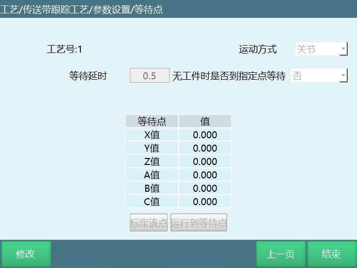
- Motion Method: After the workpiece pickup is complete, the robot returns to the safety point. If no workpiece needs to be picked up within the set time, it moves to the waiting point in the set motion method.
Joint: After workpiece tracking ends, the robot returns to the waiting point in joint motion.
Arch: After workpiece tracking ends, the robot returns to the waiting point in arch motion.
Arch Height: The maximum Z height when the robot moves in arch motion.
Arch Linear Length: When the robot lifts, Z must travel to the set length before moving X, Y coordinates (this value cannot exceed the arch height).
- Waiting Delay
Determines whether there is a workpiece within the set time. For example, if the set time is 0.5, if there is a workpiece within 0.5s, continue tracking directly. If no workpiece, the robot goes to the waiting point.
- Whether to Wait at Specified Point When No Workpiece
Yes: When no workpiece, the robot stays at the waiting point until a workpiece signal is detected before continuing tracking.
No: When no workpiece, the robot does not go to the waiting point. After tracking the current workpiece ends, it waits for the next workpiece signal.
- Calibrate This Point
Regardless of which coordinate system the point is marked in, the saved position is always in the user coordinate system.
- Move to Waiting Point
Move to the marked waiting point.
Conveyor Instructions
CONVEYOR_ON - Conveyor Tracking Start
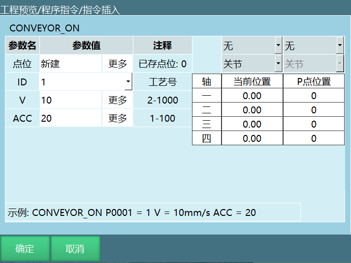
Format: CONVEYOR_ON [Instruction Name] P/GP/Workpiece Point [Point] V [Tracking Speed] ACC [Acceleration].
Function: Start tracking after the workpiece reaches the tracking range.
| Point | Reference point position data (P point, GP point, workpiece point: camera-sent point) |
|---|---|
| Workpiece Point: When the camera sends a trajectory, the first point of that trajectory is used as the workpiece point | |
| P/GP: User can select an existing position variable or create a new one. This point is the reference point during conveyor tracking and also determines the tracking height. Recommend setting this point as the midpoint of the workpiece to track. If a trajectory needs to be run on the workpiece, set this point at the first point of the trajectory | |
| ID | Conveyor tracking process number |
| V | Speed during conveyor tracking |
| ACC | Acceleration during conveyor tracking |
CONVEYOR_OFF - Conveyor Tracking End
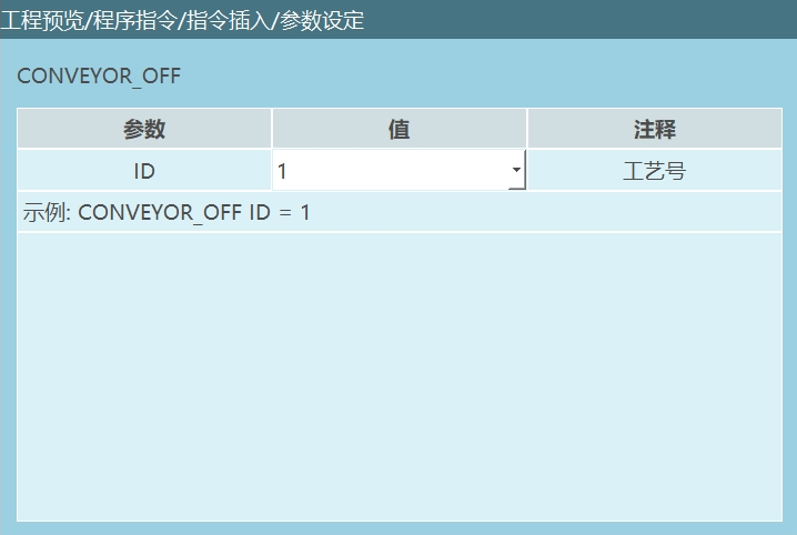
Format: CONVEYOR_OFF [Instruction Name] ID [Tracking End Process Number] GP [] I001 [].
Function: End conveyor tracking.
| ID | Conveyor tracking process number |
|---|
CONVEYOR_POS - Get Conveyor Tracking Position
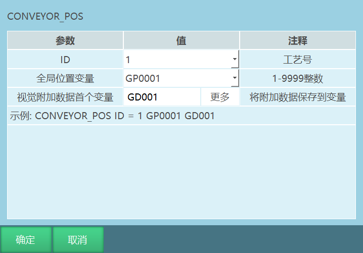
Format: CONVEYOR_POS [Instruction Name] ID [Process Number].
Function: Sensor calibration result is saved to the selected position variable, and additional data values are saved to numeric variables.
| ID | Conveyor tracking process number |
|---|---|
| Global Position Variable | When sensor triggers, sensor calibration result is saved to GP point |
| When vision triggers, each vision photo position is saved to GP point | |
| Additional Data First Variable | Additional data values are saved to variables, variable type (integer, float, string) |
| Vision process - Vision parameter interface sets additional data count. Get conveyor tracking position parameter interface sets additional data first variable. Execute this instruction to save obtained additional data values to variables. Users can use conditional judgment to call corresponding variables to pick up workpieces of different colors, shapes, etc. | |
| Example: Additional data first variable is GD001, additional data count is 2. Executing this instruction will save user-defined additional data values sequentially to GD001, GD002 | |
| If users need to pick up workpieces of different colors on the conveyor and place them at different positions, we can represent different colored workpieces with different variable values, then use IF conditional judgment to select corresponding variables for picking up different colored workpieces. Assume red workpiece is represented by GD001=1. When the camera captures a red workpiece, conditional judgment if GD001=1 picks up the red workpiece |
CONVEYOR_REMOVE - Delete Conveyor Tracking Target
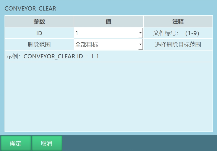
Format: CONVEYOR_REMOVE [Instruction Name] ID=1 [Tracking Process Number] 0/1 [Delete Target Range: "0" All Targets, "1" Current Target].
Function: Delete tracking signal based on selected deletion range.
| ID | Conveyor tracking process number, range [1, 9] |
|---|---|
| Deletion Range | All Targets: When the program runs and multiple conveyor tracking start signals are given, all signals except the first will be deleted |
| Current Target: When the program runs and multiple conveyor tracking start signals are given, each cycle will delete the previous signal | |
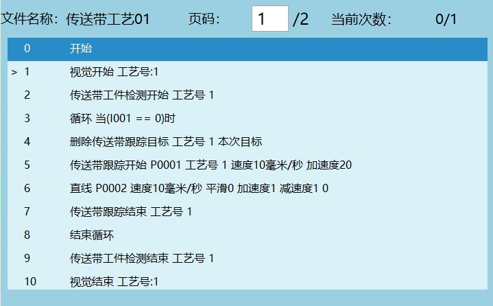
| Assume 5 workpieces. Workpiece 1 tracked, workpiece 2 tracking signal deleted and not tracked, workpiece 3 tracked, workpiece 4 tracking signal deleted and not tracked, workpiece 5 tracked | |
 |
CONVEYOR_CHECKEND - Conveyor Workpiece Detection End
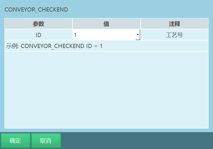
Format: CONVEYOR_CHECKEND [Instruction Name] ID [Tracking Process Number].
Function: Stop detecting workpieces. After executing this instruction, even if workpieces pass the sensor, they will not participate in queue calculation.
CONVEYOR_CHECKPOS - Conveyor Workpiece Detection Start
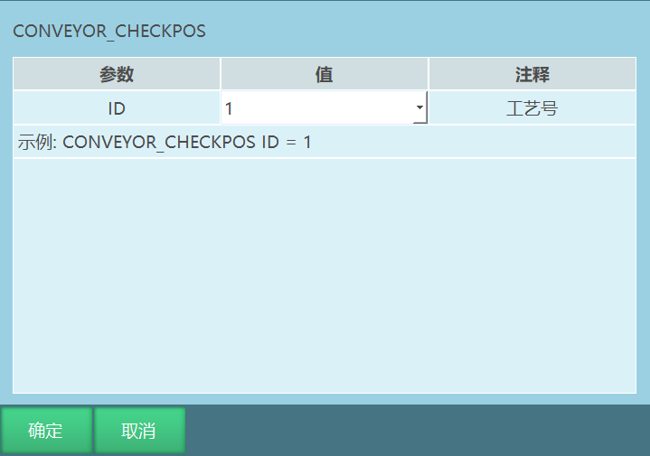
Format: CONVEYOR_CHECKPOS [Instruction Name] ID [Tracking Process Number].
Function: Execute this instruction so that workpieces passing the sensor participate in queue calculation.
| ID | Conveyor tracking process number |
|---|
Program Example Description
Example 1: Sensor trigger, running trajectory on tracked workpiece
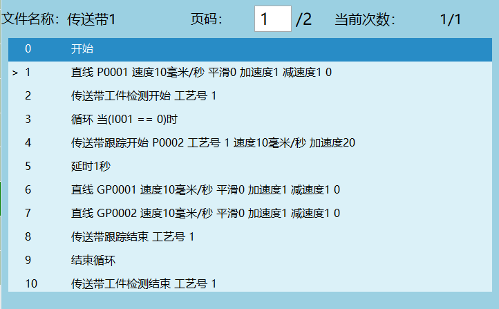
Example Description:
- Robot safety position;
- Start detecting workpieces. When workpieces pass the sensor, they start participating in queue calculation;
- Loop start, workpiece loop tracking;
- Start tracking workpiece;
- Delay 1 second;
- Run linear trajectory on tracked workpiece (GP0001-GP0002);
- End workpiece tracking;
- Workpiece loop tracking end;
- Stop detection. When workpieces pass the conveyor again, they do not participate in queue calculation.
Example 2: Sensor trigger, using external point function to run trajectory
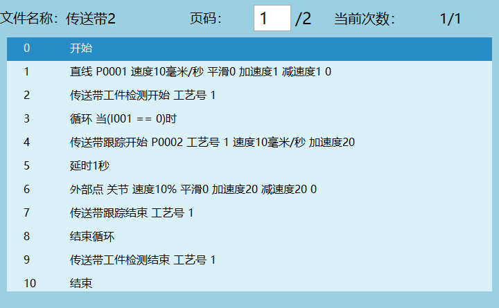
Example Description:
- Robot safety position;
- Start detecting workpieces. When workpieces pass the sensor, they start participating in queue calculation;
- Loop start, workpiece loop tracking;
- Start tracking workpiece;
- Delay 1 second;
- Use external point function to send point positions for trajectory;
- End workpiece tracking;
- Workpiece loop tracking end;
- Stop detection. When workpieces pass the conveyor again, they do not participate in queue calculation.
Example 3: Vision + Conveyor Tracking
Track workpieces through vision. Select vision for the workpiece detection signal source.
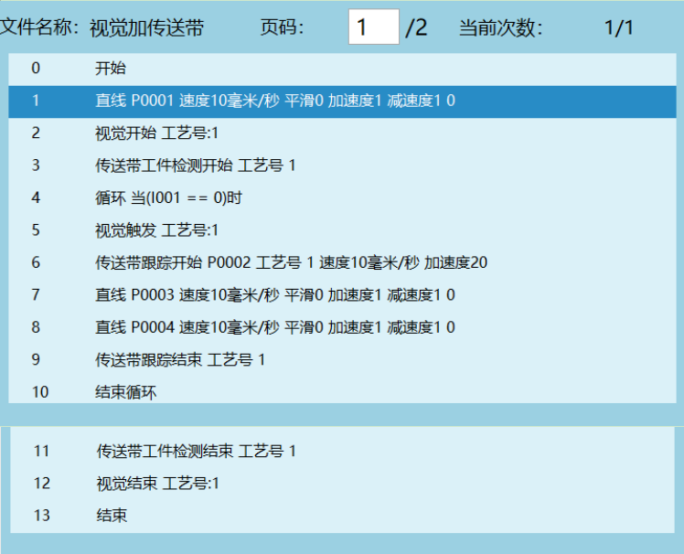
Example Description:
- Robot safety position;
- Open vision;
- Conveyor workpiece detection start;
- Loop start, workpiece loop tracking;
- Camera takes one photo, vision triggers once (when the trigger condition selected in vision software is continuous, the vision trigger instruction triggers once and workpieces can still be tracked normally. When the trigger condition is single, the camera triggers once per photo);
- Start tracking workpiece;
- Track trajectory (P0003-P0004);
- End workpiece tracking;
- Workpiece loop tracking end;
- Stop detection. When workpieces pass the conveyor again, they do not participate in queue calculation;
- Close vision.
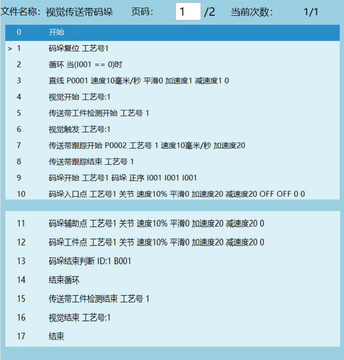
Example 4: Conveyor combined with palletizing
Vision tracks workpieces, and picked workpieces are palletized.
Example 5: Get tracking position additional data parameter description
- Vision process - Vision parameter interface sets additional data count, maximum 10.
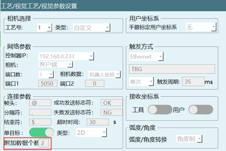
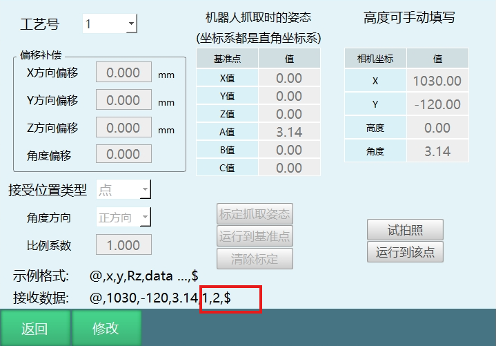
- Click vision position parameters to enter parameter interface. Check the example format change. "data" represents additional data.
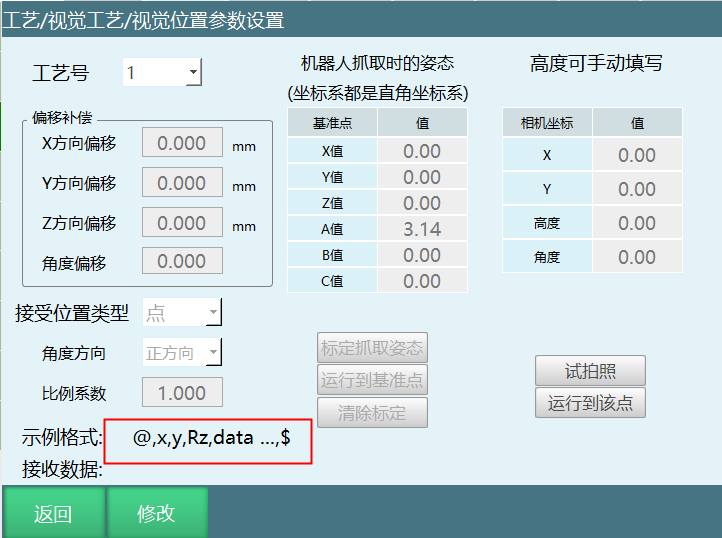
- External device: Network debugging assistant. Send point positions according to the example format on the vision position parameter interface.
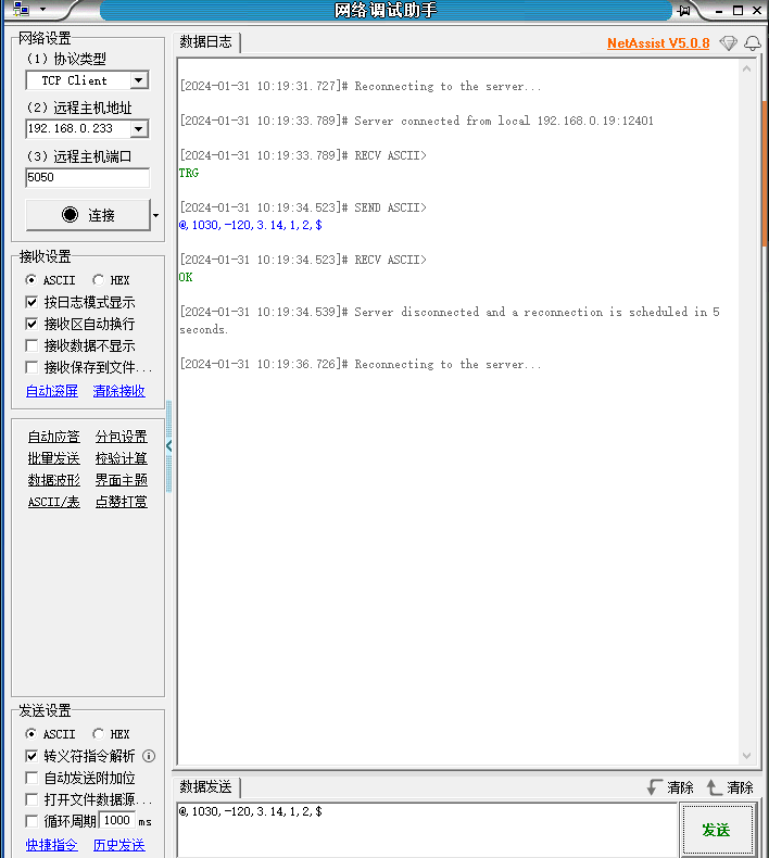
- Click trial photo. After the network assistant sends point positions, the "1,2" in the received data row represents additional data. Additional data is saved to GS001 by default, extending sequentially based on the defined additional data count.
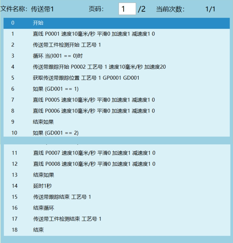
- If the get conveyor tracking position instruction is inserted, executing the instruction will save the defined additional data values to the user-selected variables (integer, float, string). Users can represent workpiece shapes and colors with numerical values (e.g., GD001=1 for red, GD002=2 for green), then use conditional judgment to track and pick up workpieces of different colors.
Example:
AI Retrieval Q&A Pairs
Q1: Robot cannot accurately pick up workpieces during conveyor tracking. What to do?
A1: Check the following: 1. Is the encoder connection normal? Ensure encoder values can be read correctly; 2. Is the conveyor calibration accurate? Especially whether the 3 calibration cone positions are correct; 3. Is the sensor calibration accurate? Ensure the sensor trigger position matches the actual pickup position; 4. Is the tracking range setting reasonable? Ensure workpieces are within the tracking range; 5. Are the tracking compensation time and encoder values set correctly to solve the lag problem.
Q2: "Tracking Exceeding Limit" warning appears during conveyor tracking. What to do?
A2: This is because the workpiece exceeds the set tracking range. Solutions: 1. Adjust the tracking range X maximum to ensure workpieces are within the tracking range; 2. Check the tracking start X point setting to ensure the robot has enough time to start tracking; 3. Check if conveyor speed is stable to avoid speed changes causing workpieces to quickly exceed the range.
Q3: Vision + conveyor tracking: camera cannot correctly identify workpieces. What to do?
A3: Check the following: 1. Is the vision process number set correctly? 2. Is the vision communication method (Ethernet/Modbus) consistent with the actual connection method? 3. Is the camera trigger method set correctly? 4. Is the vision IO signal filtering setting reasonable? 5. Is the vision latch encoder value method suitable for the current scenario?
Q4: Robot motion trajectory is unstable during conveyor tracking. What to do?
A4: Possible causes: 1. Encoder resolution setting is incorrect, causing position calculation errors; 2. Conveyor speed is unstable. Recommend using encoder method rather than constant speed setting; 3. User coordinate system calibration is inaccurate. Recalibrate the conveyor; 4. Robot speed and acceleration settings are unreasonable. Adjust the CONVEYOR_ON instruction's V and ACC parameters.
Q5: How to improve conveyor tracking accuracy?
A5: Methods to improve accuracy: 1. Ensure encoder is firmly installed to avoid vibration effects; 2. Precisely calibrate conveyor and sensor; 3. Adjust tracking compensation time and encoder values based on actual conditions; 4. Select the appropriate vision latch encoder value method; 5. Reasonably set tracking range and waiting point parameters; 6. Regularly check and maintain encoder and sensors.