Arch Motion Instruction Document
Environment
SCARA robot, standard arch motion trajectory parameters:
- Height: 25mm (displacement distance along the Z-axis)
- Width: 300mm
Location
Instruction -> Motion Control -> Arch Motion
Parameters
Detailed parameters are shown in the figure below:
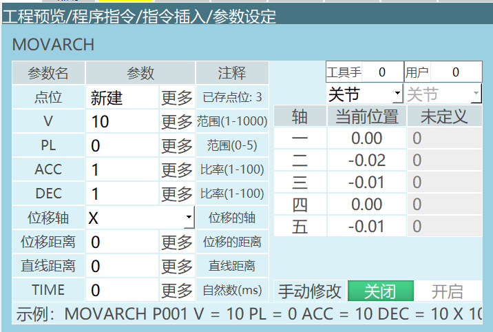
| Parameter Name | Description |
|---|---|
| P/G | Use local position variable (P) or global position variable (G). When the value is "New", inserting this instruction creates a new P variable and records the robot's current position to that P variable. |
| V | Motion speed, range 1-1000 (default Cartesian parameter maximum speed is 1000, range varies based on actual Cartesian parameters), unit is mm/s. |
| PL | Smoothing level, range 0-5. |
| ACC | Acceleration ratio, range 1-100, unit is percentage. |
| DEC | Deceleration ratio, range 1-100, unit is percentage. |
| Displacement Axis | (X, Y, Z) The axis that undergoes displacement during arch motion. Standard arch motion displaces along the Z-axis direction. |
| Displacement Distance | The distance to displace along the displacement axis. Standard arch motion displaces 25mm along the Z-axis. |
| TIME | Time, range is non-negative integer, unit is ms. Advance time to execute the next instruction. |
Note: When modifying the speed of a linear instruction, the acceleration/deceleration ratios will automatically display in a 1:10 ratio relationship with the speed. If you need to modify the acceleration/deceleration ratios, you can do so manually.
Usage Method
- Create a new project file, then click Open > Insert > Motion Control > Arch Motion.
- Example:
MOVARCH P0001 V=100mm/s PL=5 ACC=10 DEC=10 Z 25 0
- Description:
Arch motion supports single-step and trial run;
Arch motion instruction creates a new linear distance.
- Arch motion trajectory diagram
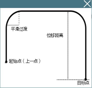
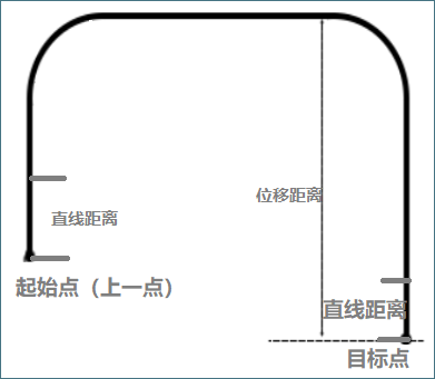
Parameter introduction:
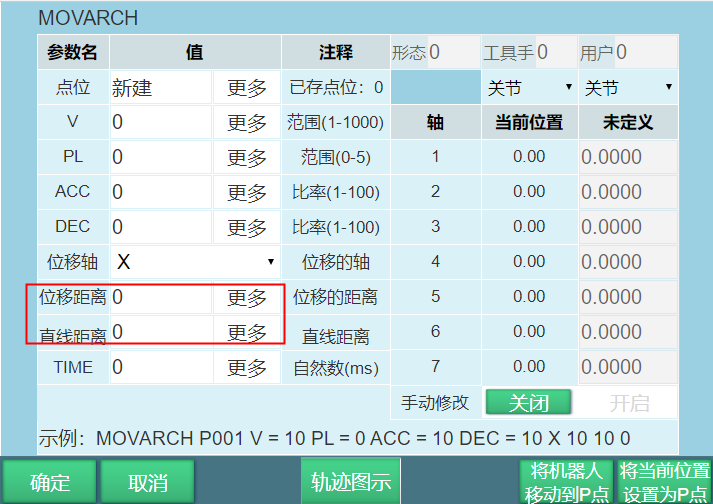
Linear distance (as shown in the figure below): Ensures that the displacement distance traveled by the robot includes a segment that moves in a straight line (i.e., the vertical movement distance between the arch motion's ascending start and descending end).
Usage method: The linear distance cannot be greater than the displacement distance; the linear distance range is: [0,5000] (unit: mm).
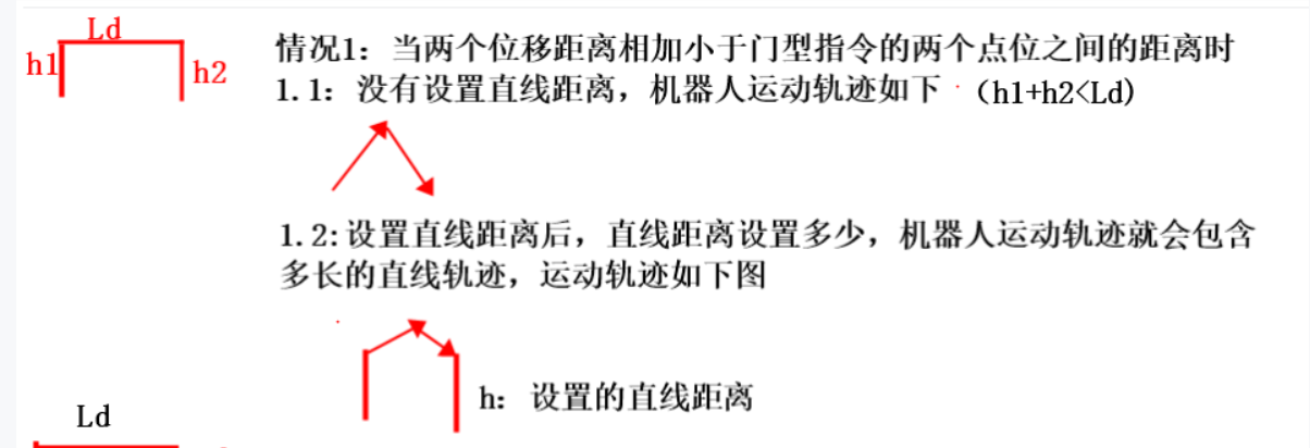
Ld is the distance between the starting point and target point of the arch motion.
h1 and h2 are the displacement distances at both ends respectively.
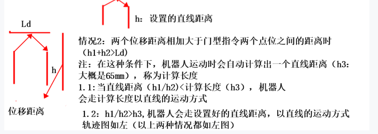
L: Calculated length (from the start of motion, the robot's trajectory is guaranteed to be a straight line until this calculated length is completed).
There are two cases:
h1+h2 < Ld (when the sum of displacement distances at both ends is less than the distance between two arch motion instruction points):
Whatever linear distance is set, the robot will travel that distance in a straight line trajectory.
h1+h2 > Ld (when the sum of displacement distances at both ends is greater than the distance between two arch motion instruction points, the robot will automatically calculate an L (calculated length))
If the linear distance is less than the calculated length, the robot travels the calculated length in a straight line trajectory.
If the linear distance is greater than the calculated length, the robot travels the linear distance length in a straight line trajectory.
Q&A for Retrieval
Q: What are the height and width parameters of the standard arch motion trajectory?
A: Height is 25mm, width is 300mm.
Q: How to achieve fast smooth transitions during arch motion?
A: Setting PL can smoothly complete the arch motion at a faster speed.