Palletizing Process
Process Introduction
Robot palletizing is mainly used in food, beverage, logistics and other industries. It is also a typical example of industrial robot applications. With different grippers, it can realize boxing and palletizing of various shapes of finished products in different industries. The significance of palletizing is to stack piles of items into stacks through a certain pattern, making items easy to transport, unload and store.
Traditional palletizing is completed manually. This palletizing method has high labor costs and low production efficiency, and cannot meet the automation requirements of today's production.
To improve transport efficiency and palletizing quality, save labor costs, and ensure the personal safety of enterprise employees, palletizing robots will be more widely used in production.
Simple Palletizing / Complete Palletizing
Enter Process/Palletizing Process/Palletizing Parameters. Supports 99 process number parameters. Can select simple palletizing and complete palletizing, as shown below.
Clear Parameters: Clear parameters of currently selected process number, complete palletizing/simple palletizing.
Copy Parameters: Parameters of currently selected process number, complete palletizing/simple palletizing can be copied to the desired process number.
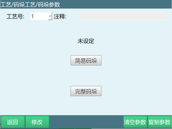
Note: Simple palletizing process number is best not to use the same process number as complete palletizing. If simple palletizing process number is 1 and parameters are set, then change process number 1 to complete palletizing, complete palletizing parameters need to be reset. Selecting different process numbers can save time and avoid program runtime errors.
Complete Palletizing
Parameter Setting
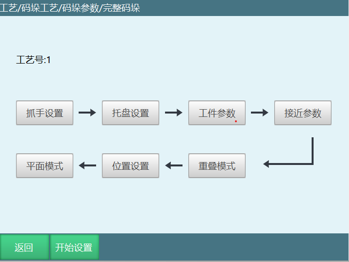
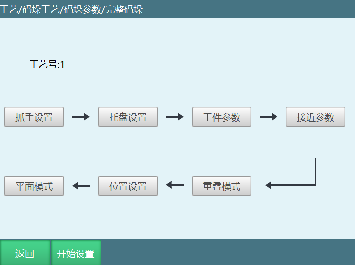
Complete palletizing can perform gripper setting, pallet setting, workpiece parameters, approach parameters, overlap mode, position setting, and plane mode according to the process, as shown below:
Gripper Setting
Gripper setting is to set the tool hand used during palletizing.
Two suction cups picking materials separately (one suction cup picks first, then switch to another suction cup), then set as two grippers;
Two suction cups picking materials simultaneously, then set as one gripper;
If two suction cups placing materials separately (one suction cup places first, then switch to another suction cup), then set as two grippers;
Two suction cups placing materials simultaneously, then set as one gripper.
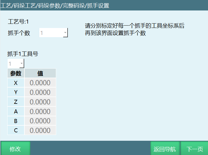
Note: Please calibrate the gripper (tool hand) in [Settings-Tool Hand Calibration] interface in advance, then set the gripper in this interface.
Term Explanation:
Gripper Count: Number of grippers, set according to actual situation, maximum 4 grippers.
Gripper X Tool Number: Set the tool hand number corresponding to the gripper (X in figure is 1). Tool hand parameters need to be calibrated in advance.
Parameter Value**: **After tool hand calibration interface completes tool coordinate calibration, select the calibrated tool hand number in this interface to display each axis parameter value.
Pallet Setting
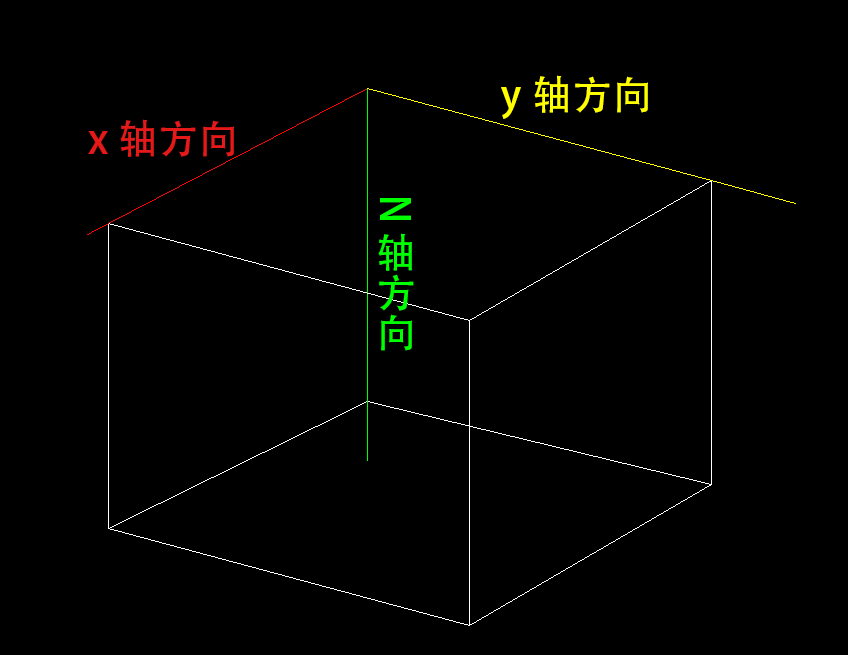
Pallet setting is to set the pallet user coordinate project. In this interface, the pallet origin, pallet Y direction and pallet X direction need to be calibrated.
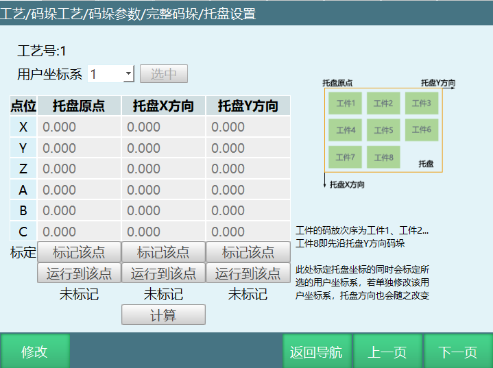
User Coordinate System: Pallet coordinate. Select the user coordinate to calibrate as needed. Calibrate pallet coordinate (user coordinate). If the coordinate system position is changed in user coordinate calibration later, the coordinate system here will also change.
Note: Please use the tool hand selected for gripper 1 for calibration. When not calibrating user coordinate (pallet coordinate), user coordinate parameter value is 0, same as Cartesian coordinate system.
When marking X and Y directions, must be based on robot's original X, Y direction. Otherwise, the marked pallet Z direction will be downward, and the second layer will be stacked downward during palletizing!
Workpiece Parameters
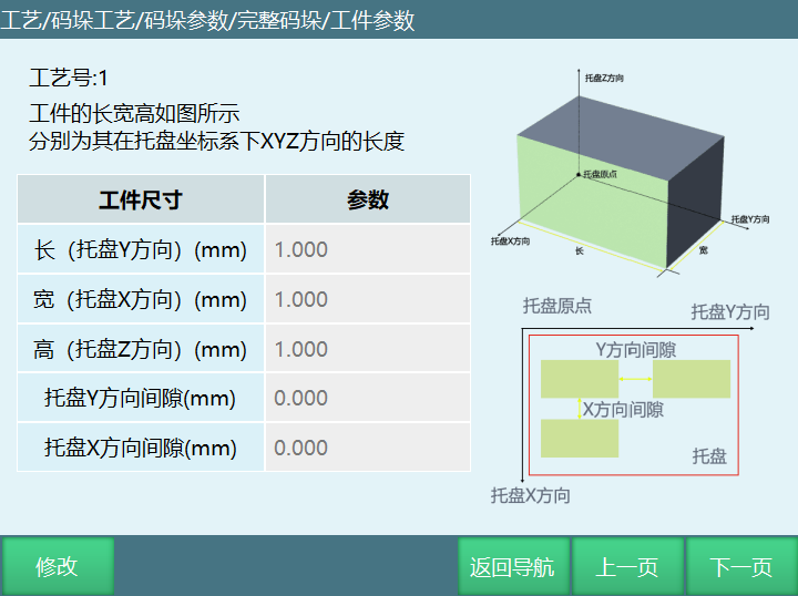
Workpiece parameters can set the length, width, height and gap of the workpiece to be palletized in the user coordinate system.
Length, width, and height are the lengths in YXZ directions of the pallet coordinate system (user coordinate system), as shown below:
Workpiece Size Parameter Description:
Length: Length of workpiece in Y direction of pallet coordinate system.
Width: Length of workpiece in X direction of pallet coordinate system.
Height: Length of workpiece in Z direction of pallet coordinate system.
Pallet Y Direction Gap: Gap distance between two workpieces in Y-axis direction of pallet coordinate system.
Pallet X Direction Gap: Gap distance between two workpieces in X-axis direction of pallet coordinate system.
Approach Parameters
Usage Scenario
Place workpiece into workpiece point at set angle and speed. Suitable for some large packaging and closely placed scenarios. This function supports any stack pattern with individual workpiece approach and leave speed settings and approach method.
Compared to version 22.07, there is an additional approach parameter in the process.
Parameter Description: Approach method is divided into descent approach and approach descent, as well as XYZ direction offset distance.
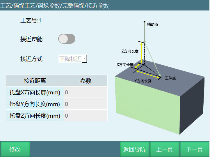
Approach Enable
Need to open to use palletizing approach function. If enable button is opened but approach distance is not set, approach enable will not take effect.
Approach Method
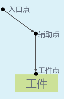
Descent Approach: Robot goes to auxiliary point first, then moves to approach point according to offset distance, then moves to workpiece point.
Approach Descent: Robot goes to auxiliary point first, then moves to approach point according to offset distance, from approach point moves above workpiece point then moves to workpiece point.
Running trajectory reference above figure.
Approach Distance
Divided into XYZ directions. According to figure, specific approach point is workpiece point offset by XYZ direction values. But if approach direction is selected, for example, if upper approach direction is selected, then approach direction takes priority. If no direction is selected, Z value is calculated first then offset.
Approach Direction: Eight directions.
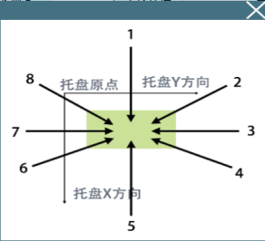
Can be viewed in the approach description button.
Plane Mode
In palletizing plane mode, custom stack pattern has added individual workpiece approach and leave speed settings. If not filled, default approach point instruction speed is used. Speed differs based on instruction interpolation method. If interpolation is joint, speed less than 100 is corresponding value, greater than 100 is 100. Acceleration/deceleration defaults to equal speed. If linear, fill amount is actual amount (except negative). Cannot exceed Cartesian parameter acceleration/deceleration, default to 10% of speed.
Approach Speed: Speed for running to approach point.
Leave Speed: Speed for running from workpiece point to approach point.
Also can set individual or overall approach direction.
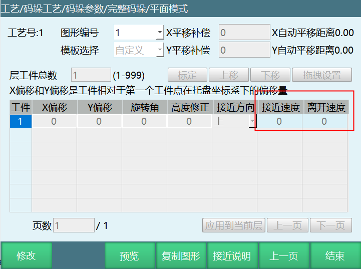
Apply to Current Layer
Set the selected workpiece's approach direction, approach and leave speed as parameters for all workpieces in the entire layer.
Position Debug
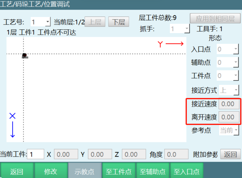
In position debug, individual workpiece approach and leave speed and approach direction can also be set.
Gripper: Position debug interface adds gripper selection option, as shown. Operation steps: Process → Palletizing Process → Position Debug. Can adapt to different palletizing positions by modifying different grippers.
Palletizing Approach Point
New instruction palletizing approach point is the transition point between auxiliary point and workpiece point, which is the point that the approach method needs to reach.
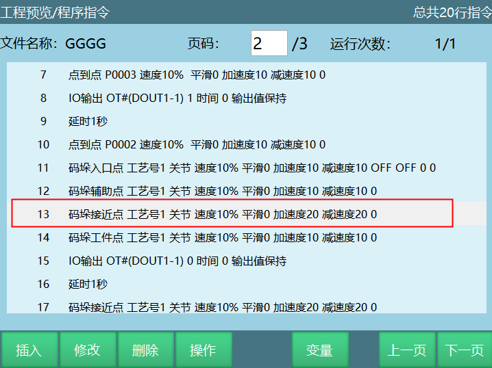
Parameter setting same as other palletizing points.
Overlap Mode
Overlap mode can set palletizing layer and pattern template selection, and other related parameters, as shown below:
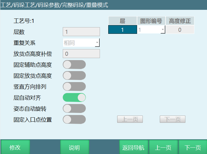
Term Explanation:
Layer Count: Total number of palletizing layers, fill according to actual needs.
Repeat Relationship: Repeat relationship between each layer.
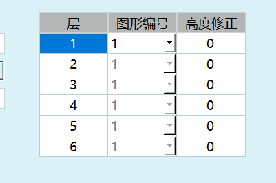
Select Same: Each layer uses the same pattern template.
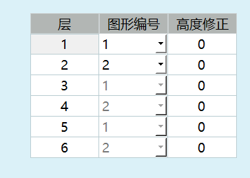
Select Alternate: Pattern template alternates every two layers.
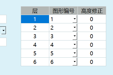
Select Custom: User selects the pattern template for each layer.
Same: Each layer pattern template is the same. Palletizing uses the same pattern template. When selecting this option, only the first layer in the right list can be modified. After modification, all layers below will change accordingly. Below figure shows 6 layers selected, repeat relationship selected as same.
Alternate: Two pattern templates used alternately. After selecting this option, only the first two layers in the right list can be modified. After modification, all layers below will repeat the pattern numbers of these two layers. Below figure shows 6 layers selected, repeat relationship selected as alternate.
Custom: Each layer pattern template can be individually set. Below figure shows 6 layers selected, repeat relationship selected as custom, as shown below:
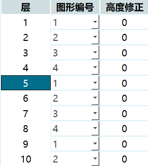
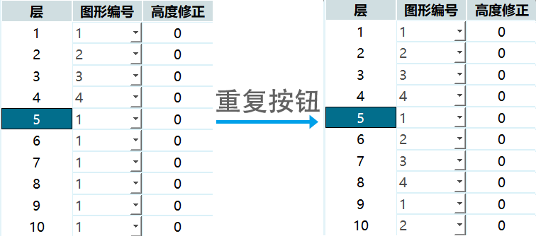
Repeat: When repeat relationship uses custom and layer count is large, if all layers repeat the first N layers' pattern templates, after filling the first N layers' pattern templates, select the N+1 layer, click this button, layers below will automatically repeat (can only use this function on first page). See figure below.
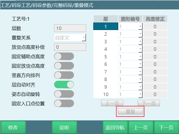
Fixed Auxiliary Point Height: If palletizing layer count is two, opening this button makes the first layer workpiece and second layer workpiece auxiliary points the same position. When running the second layer workpiece, auxiliary point will not offset in Z+ direction.
For example: Palletizing workpieces in a box enclosed on all sides. If palletizing many workpieces, the set workpiece auxiliary point will become higher and higher as palletizing count increases, likely exceeding robot joint parameter limits. To prevent such errors, open fixed auxiliary point height button and set fixed auxiliary point height position. This way, as palletizing count increases, auxiliary point height remains the same position, avoiding joint parameter limit exceedance and ensuring operator safety.
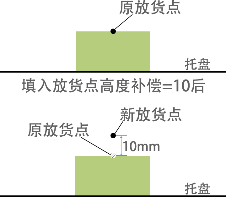
Delivery Point Height Compensation: After filling, all workpiece delivery point heights will offset. Offset height can be filled according to actual needs. Positive value offsets in Z+ direction, negative value offsets in Z- direction (this parameter is invalid during depalletizing, height compensation effect can only be seen during program execution).
Fixed Delivery Point Height: When selected, delivery point height is the same for each layer during palletizing. Height is the marked workpiece point height (only effective during palletizing). If palletizing layer count is greater than one (two layers as example), opening this button makes each layer's each workpiece point the same height. When palletizing second layer, workpiece point height will not offset in Z+ direction.
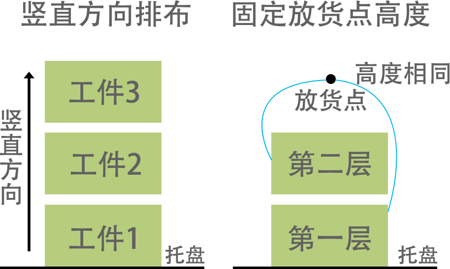
Vertical Direction Arrangement: After selecting vertical direction arrangement, first complete one vertical column, then move to the next vertical column.
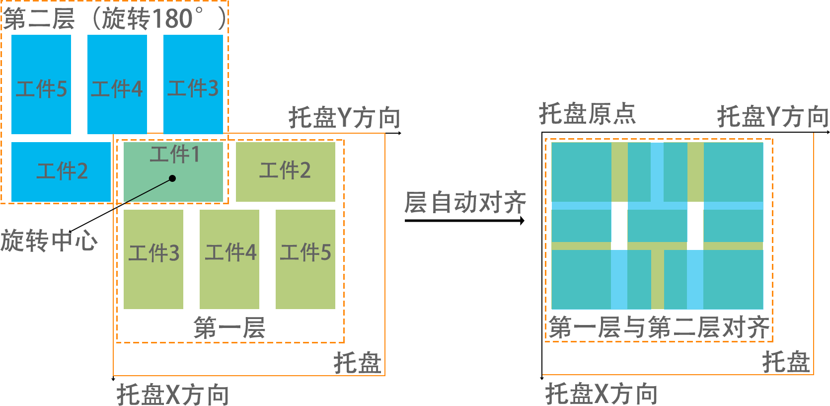
Layer Auto Align: Selecting layer auto align will automatically align each layer template, automatically calculating X-axis, Y-axis offset.
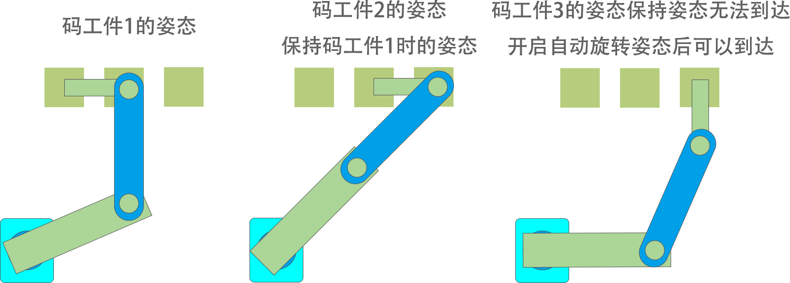
Posture Auto Rotation: When selected, if during palletizing the tool hand cannot reach auxiliary point and delivery point with a fixed posture, but can reach after rotating the tool hand posture, it will automatically rotate. This function is only effective when both auxiliary point and workpiece point use joint interpolation.
Fixed Entry Point Position: After picking, each workpiece will be at the same entry point. Z-axis will be optimized when entering the entry point.
Position Setting: Can set palletizing workpiece point, auxiliary point, entry point. Please bring the tool hand selected in gripper setting for position marking.
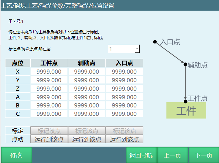
Mark Layer Number: Current calibration workpiece point is on which layer. Saves the process of clearing stack pile. Can directly select mark current layer.
Workpiece Point: First picking point or last delivery point of this marked layer (Note: Workpiece sequence in palletizing parameter setting interface is in palletizing order. Depalletizing sequence is reversed).
Auxiliary Point: Used together with workpiece point, allowing workpiece to be placed at workpiece point more safely. Generally set above workpiece point. If workpiece needs rotation angle, it will rotate before reaching auxiliary point. This point will automatically offset with workpiece placement position.
Entry Point: Pallet entry point. To prevent robot collision with other objects, set robot safe position as entry point as much as possible. This point will automatically offset in Z-axis direction with workpiece placement position. Palletizing entry point instruction opens XYZ optimization. When running to entry point, ABC axis coordinates change.
Mark Point: Robot moves to position first, then click mark point.
Run to Point: After marking value and clicking save, can move to marked point. Without saving, move to previously marked point. To move to this point, press DEADMAN button then click this button (Note: Please bring the tool hand selected in gripper setting for position marking).
Plane Mode
This mode sets palletizing pattern template:
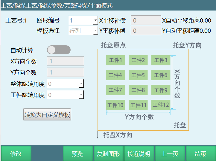
Pattern Number: Pattern template number.
Template Selection: Divided into 4 fixed pattern templates and custom pattern templates. They are rows and columns, interlocking, return shape, five-flower stack, and custom.
X Translation Compensation: Offset of overall pattern template relative to original palletizing position on pallet coordinate system X-axis.
Y Translation Compensation: Offset of overall pattern template relative to original palletizing position on pallet coordinate system Y-axis.
Auto Calculate: Based on pallet setting interface, generate a rectangular pallet from calibrated user coordinate system. Automatically calculate how many workpieces can be placed in X direction and Y direction based on workpiece size.
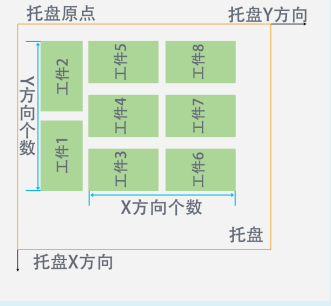
X Direction Count (rows and columns template, interlocking template): Number of workpieces in X direction (interlocking X direction count is number of workpiece long edge on X-axis).
Y Direction Count (rows and columns template, interlocking template): Number of workpieces in Y direction (interlocking Y direction count is number of workpiece long edge on Y-axis).
Overall Rotation Angle (rows and columns template, interlocking template, return shape template): Overall clockwise rotation angle around first workpiece point. Can rotate 0°, 90°, 180°, -90°.
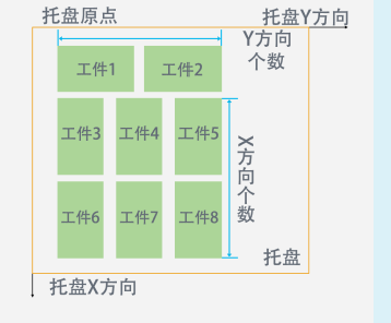
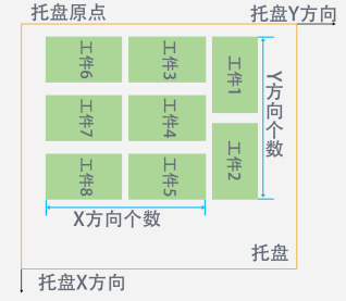
(Overall Rotation Angle 0°) (Overall Rotation Angle 90°)
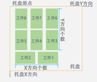
(Overall Rotation Angle 180°) (Overall Rotation Angle -90°)
Workpiece Rotation Angle (rows and columns template, interlocking template, return shape template, five-flower stack template): All workpieces in pattern template rotate clockwise by this angle. Can rotate 0°, 90°, 180°, -90°.
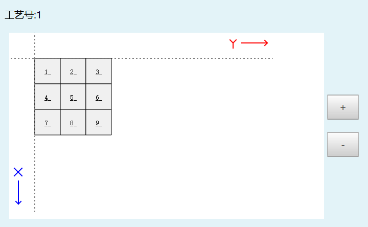
Preview: Preview the set pattern template. Can be used to check if pattern template is set correctly. Here template selects interlocking template. X direction workpiece count is 3, Y direction count is 3.
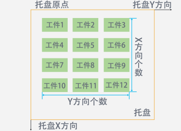
Rows and Columns: Workpiece direction of entire layer pattern template is consistent, placed in sequence. Below figure shows X direction workpiece count is 4, Y direction count is 3.
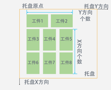
Interlocking: Workpiece directions include horizontal and vertical, interlocking arrangement (this template's X direction count is number of workpiece long edge on X-axis, Y direction count is number of workpiece long edge on Y-axis).
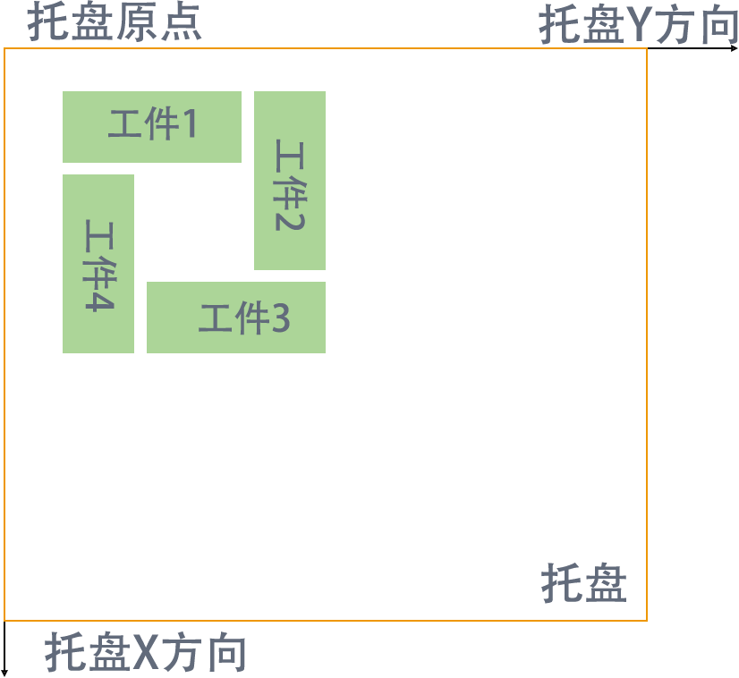
Return Shape: 4 workpieces per layer, arranged in return shape (second workpiece rotated 90° clockwise from first, third rotated 180° clockwise from first, fourth rotated 90° counterclockwise from first).
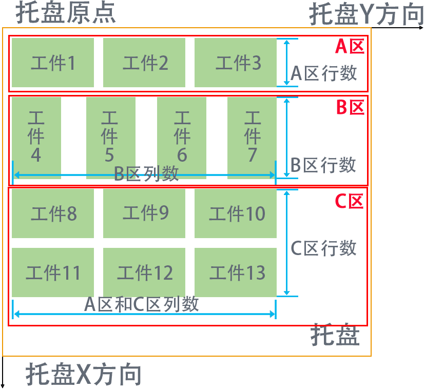
Five-Flower Stack: Workpieces divided into three areas: Area A, Area B, Area C. Column count for Area A and Area C can be set together. Area B column count set separately (as shown, workpieces 4-7 in Area B rotated 90° clockwise from workpieces 1-3 in Area A and workpieces 8-13 in Area C). As shown in Figure 1, workpieces in Area A and Area C maintain left-right alignment based on Area B with the most columns.
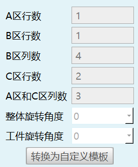
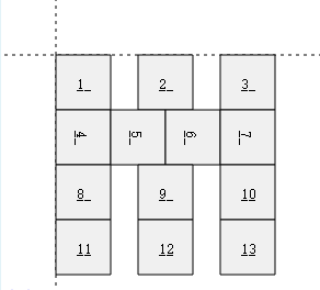
Figure 1
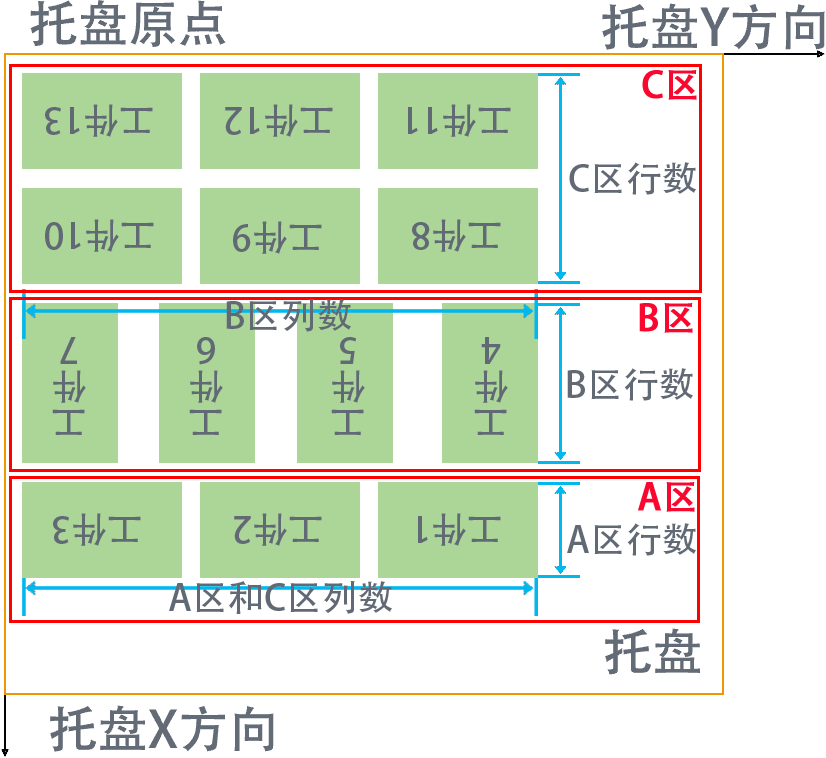
Overall Rotation Angle 0° Overall Rotation 180°
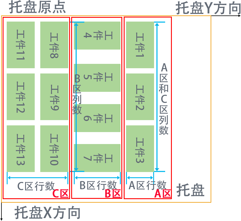
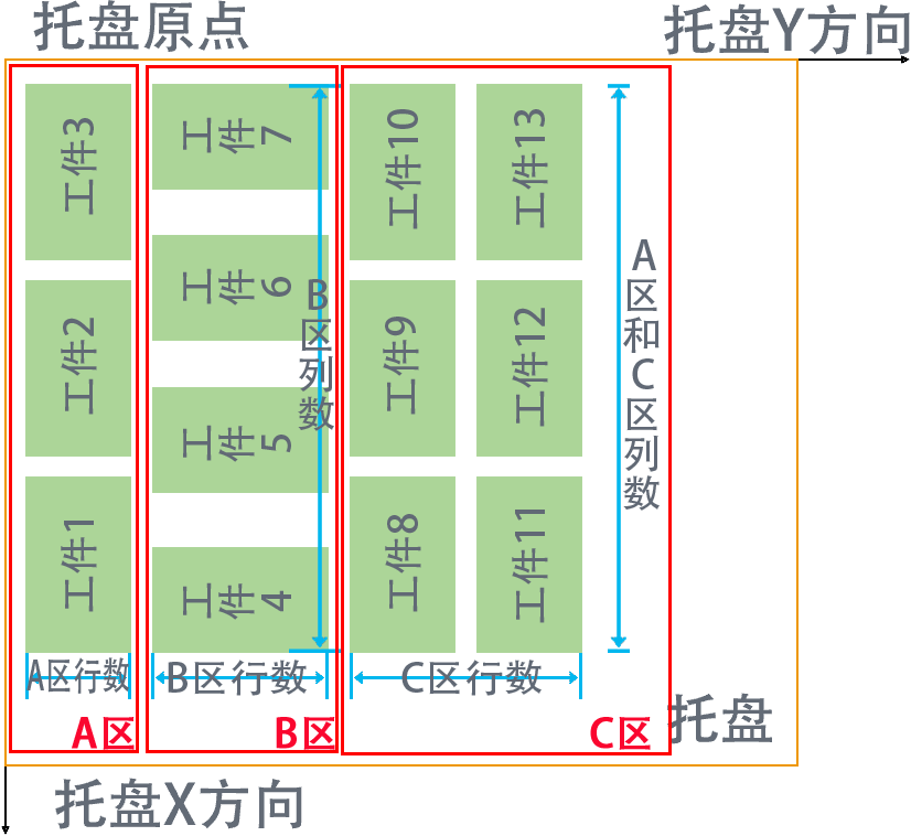
Overall Rotation 90° Overall Rotation -90°
Custom: Custom pattern template.
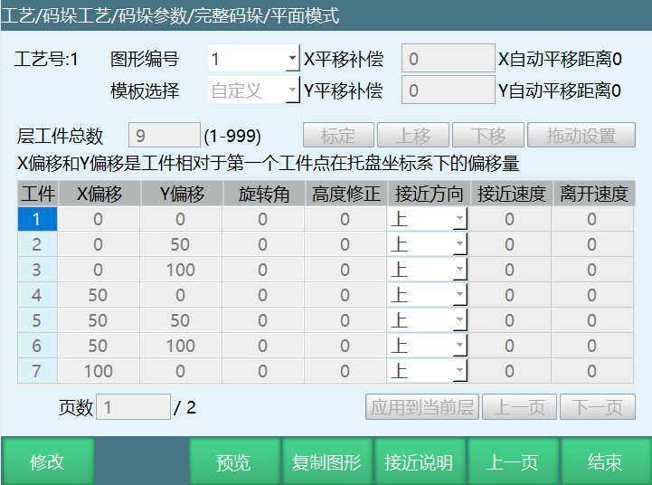
Layer Workpiece Total: Total number of palletizing workpieces, set according to actual needs. Note: Modifying workpiece total will clear all workpiece parameters.
Calibration: Can set workpiece palletizing point positions. After determining point positions, click calibrate button. If the first set palletizing workpiece point positions need modification, click workpiece number, move robot to desired position, then click calibrate. Workpiece point position modification is complete.
Move Up: After workpiece point position calibration is complete, to set palletizing workpiece 2 position as palletizing workpiece 1 position, click move up button. Workpiece 1 position will change. Here using two workpieces as example.
After workpiece 2 moves up:


Move Down: After workpiece point position calibration is complete, to set palletizing workpiece 1 position as palletizing workpiece 3 position, click move down button. Workpiece 3 position will change.
After workpiece 1 moves down:

X Offset: Workpiece point offset on X-axis.
Y Offset: Workpiece point offset on Y-axis.
Rotation Angle: Angle of workpiece rotation relative to previous workpiece point.
Height Correction: After filling, workpiece point, auxiliary point, entry point height will offset during this workpiece palletizing. Positive value offsets in Z+ direction, negative value offsets in Z- direction. Can correct workpiece point, auxiliary point, entry point height.
Drag Setting: After palletizing workpiece count is set, click drag setting button. As shown, can drag workpiece point to any desired position. Custom can not only fill XY offset, but also directly drag workpiece.
Note: Before entering drag setting, first set layer workpiece total in custom, click save, then click modify-drag setting. After drag setting is complete, first click save button in drag setting, return to custom interface, then click save again.
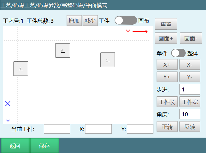
Increase: Increase workpiece count. Increase workpiece count as needed.
Decrease: Decrease workpiece count.
Workpiece/Canvas: Button off can drag workpiece, button on can drag canvas.
Reset: Reset canvas.
View+: Zoom in.
View-: Zoom out.
Single/Overall: Single/Overall workpiece offset in X or Y direction. Open single/overall button, can offset all workpieces in X or Y direction. Close single/overall button, can offset currently selected workpiece in X or Y direction.
X+/X-: Overall offset in X positive or negative direction step value.
Y+/Y-: Overall offset in Y positive or negative direction step value.
Step: Workpiece offset amount in X or Y direction.
Angle: Set rotation angle each time. Open single/overall button, all workpieces will rotate. Close single/overall button, can rotate currently selected workpiece.
Forward/Reverse: Workpiece rotates by set angle value on its own.
Simple Palletizing
Parameter Setting
Simple palletizing parameter setting can perform gripper setting and position setting according to the process.
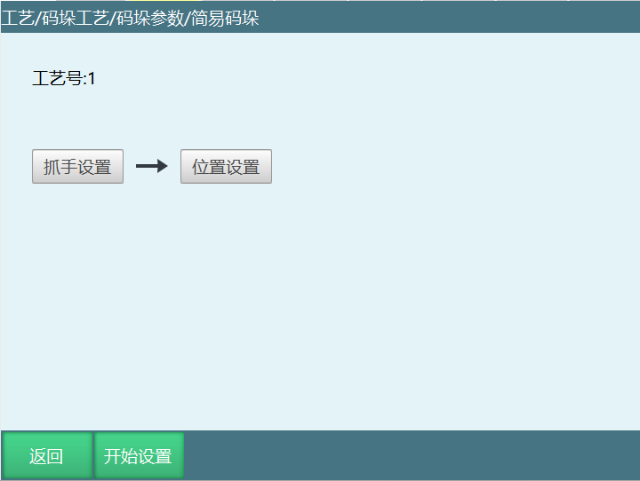
Current Usage Type: When simple palletizing and complete palletizing share palletizing number, need to set correct type before use.
Gripper Setting
Gripper setting can select palletizing gripper (tool hand). Please calibrate the gripper (tool hand) in [Settings-Tool Hand Calibration] interface in advance, then set the gripper in this interface, as shown:
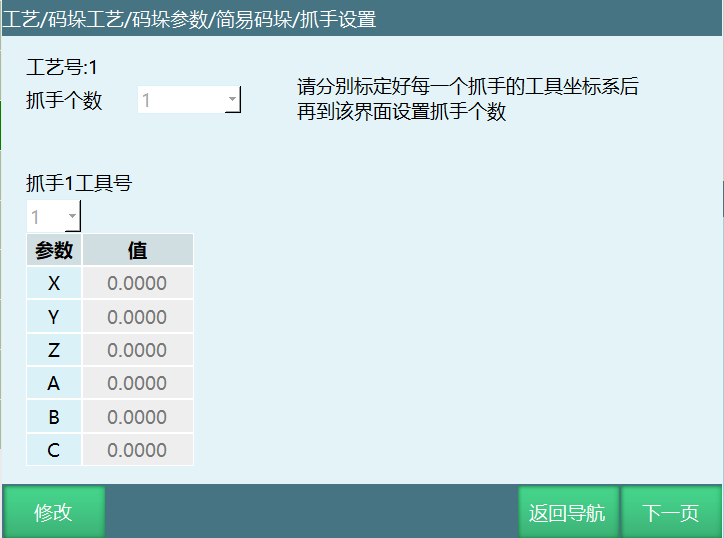
Gripper Count: Number of grippers, set according to actual situation.
Gripper X Tool Number: Set the tool hand number corresponding to the gripper. Tool hand parameters need to be calibrated in advance.
Parameter Value: Parameter value is tool hand end offset. Can only select here, cannot calibrate.
Position Setting
Simple palletizing only provides rows and columns mode stack pattern. All palletizing directions and position points are marked. Even if the marked pattern is not rectangular, it will palletize according to marked direction.
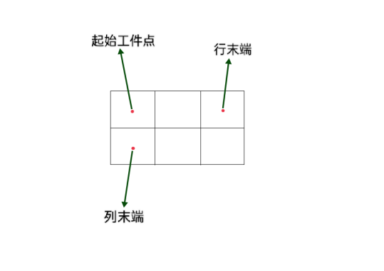
Simple palletizing only needs to set palletizing gripper and mark 6 position points. Gripper setting is same as complete palletizing. If palletizing has multiple grippers for picking and placing separately, please use the first gripper to mark position points. Other grippers' actions will be automatically calculated.
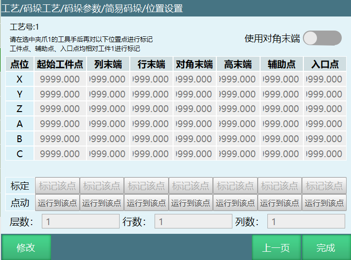
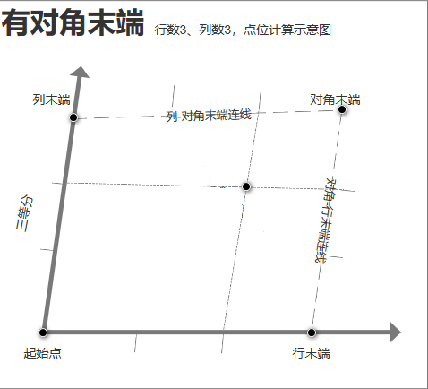
Start Workpiece Point: Position of first workpiece during palletizing.
Column End: Position of last workpiece in column (user coordinate X-axis) direction during palletizing.
Row End: Position of last workpiece in row (user coordinate Y-axis) direction during palletizing.
Height End: Position of first workpiece of last layer during palletizing.
Diagonal End: Intersection point of row end diagonal end line and column end diagonal end line. Used to calibrate position offset when palletizing has many points.
Auxiliary Point: Palletizing auxiliary point. Recommended to set above start workpiece point.
Entry Point: Entry point during palletizing. Recommended to set as a safe point outside the pallet.
Layer Count: Total number of palletizing layers.
Row Count: Total number of palletizing rows.
Column Count: Total number of palletizing columns.
Generate File
Using generate file can generate standard palletizing/depalletizing programs. Need to set parameters in process number in advance.
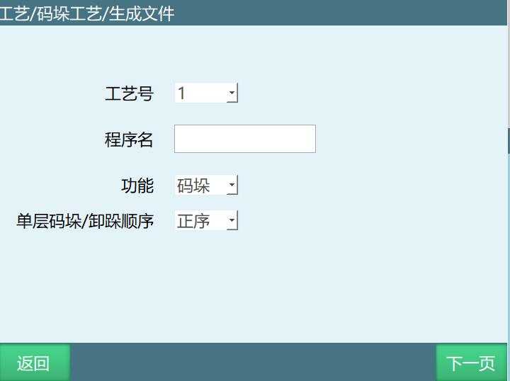
Simple palletizing generate file function, cannot be used without IO. As shown below:
Current Usage Type: When simple palletizing and complete palletizing share palletizing number, need to set correct type before use.
Parameter Introduction:
Process Number: After selecting process number, confirm whether palletizing current usage type is set.
Program Name: Must start with English letters (pure Chinese also works).
Function: Palletizing, Depalletizing.
Single Layer Palletizing/Depalletizing: Forward order, Reverse order.
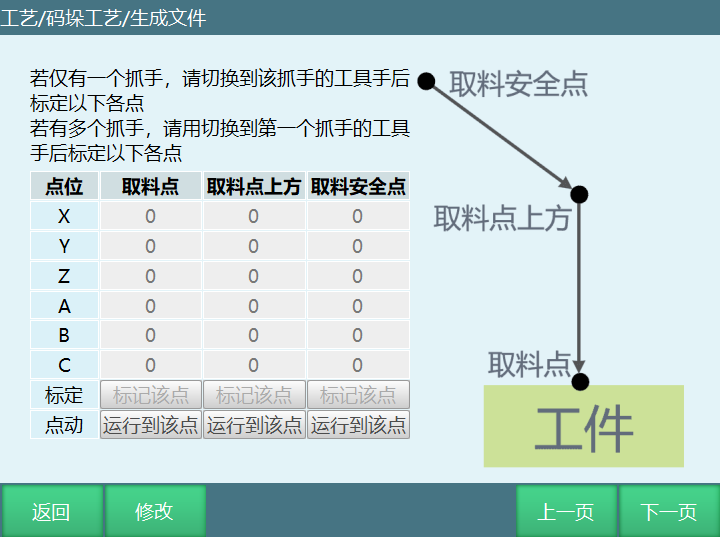
Mark Point: Teach to corresponding point and click calibrate point.
Run to Point: Click run to point to verify if point teaching is correct.
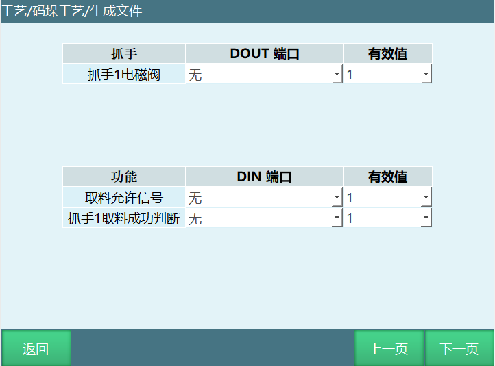
Gripper Solenoid Valve: Gripper IO output signal. Gripper solenoid valve DOUT port must be set. Generate file function only supports 1 output. For multiple outputs, return to project to modify output signal instruction after job file generation.
Picking Permission Signal: Wait for picking permission signal before palletizing picking. Select based on own situation.
Gripper Picking Success Signal: Judge gripper picking success signal.
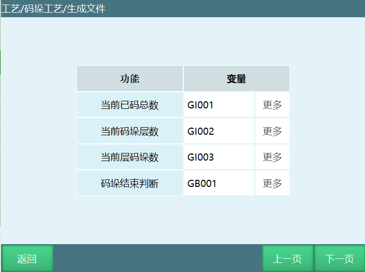
Note: Current total count, current palletizing layer count, current layer palletizing count - if variable type is not selected during job generation, during palletizing program execution, we can view in Process Bar-Palletizing Process interface.
Current Total Count: Cache current total count variable value to set variable.
Current Palletizing Layer Count: Cache current palletizing layer count variable value to set variable.
Current Layer Palletizing Count: Cache current layer palletizing count variable value to set variable.
Palletizing End Judgment: After palletizing completes, change variable value to exit while loop.
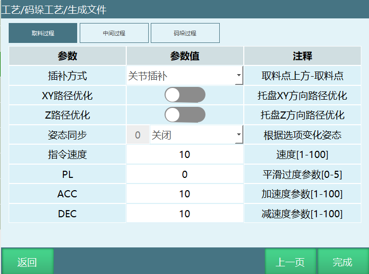
Picking Process: Above picking point, picking point. Can change to joint interpolation or linear interpolation.
Middle Process: Picking safe point, palletizing entry point. Can change to joint interpolation or linear interpolation.
Palletizing Process: Palletizing auxiliary point, workpiece point. Can change to joint interpolation or linear interpolation.
XY Path Optimization: Click to enable, can optimize pallet XY direction path.
Z Path Optimization: Click to enable, can optimize pallet Z direction path.
Posture Synchronization: