Human-Robot Collaboration
This chapter mainly introduces the role of dynamics and how to use it. Due to the complex nonlinearity, time-varying uncertainty, and strong coupling of robots (especially during high-speed motion), the servo motors of each robot joint must provide sufficient force and torque to drive the robot's links and joints in order for the robot to move at the desired speed and acceleration. Otherwise, the links will suffer from sluggish motion that affects the robot's positioning and trajectory tracking accuracy. Therefore, a feedforward torque control based on the dynamics model must be established to calculate feedforward compensation torques in real time.
Human-robot collaboration (HRC) refers to work in which humans and automated machines share a workspace and perform tasks simultaneously.
Robot Identification
Applicable to RTL-25.01.0 version
Before using force functions, you must first set up the dynamics parameters so that the controller can establish the robot's dynamics model.
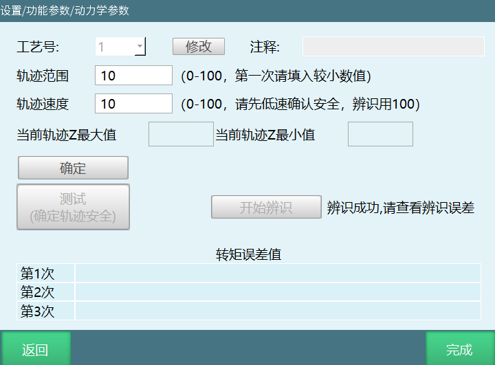
To set dynamics parameters, go to "Settings/Function Parameters/Human-Robot Collaboration/Dynamics Parameters". Before entering the identification interface, carefully read the relevant precautions for identification. When performing trajectory testing on the robot, the range and speed should be set from small to large, gradually determining a maximum trajectory range value that will not collide with the surrounding environment. Then set the trajectory speed to 100, and identification can begin. During identification, do not operate the teach pendant unless necessary, and personnel must stay away from the robot. If you need to stop identification, you can stop the robot by clicking Stop on the teach pendant, pressing the emergency stop button, or switching modes.
Parameter Description
Process Number: A dropdown box for adding new process numbers 1-9. Click Modify to change the process number.
Comment: Corresponding process number can have a comment for differentiation.
Trajectory Range: Calculate the robot's maximum and minimum motion range based on the trajectory range.
Trajectory Speed: The speed of the robot during operation, independent of the global speed.
Current Trajectory Z Max / Current Trajectory Z Min: Indicates the range of the current trajectory Z.
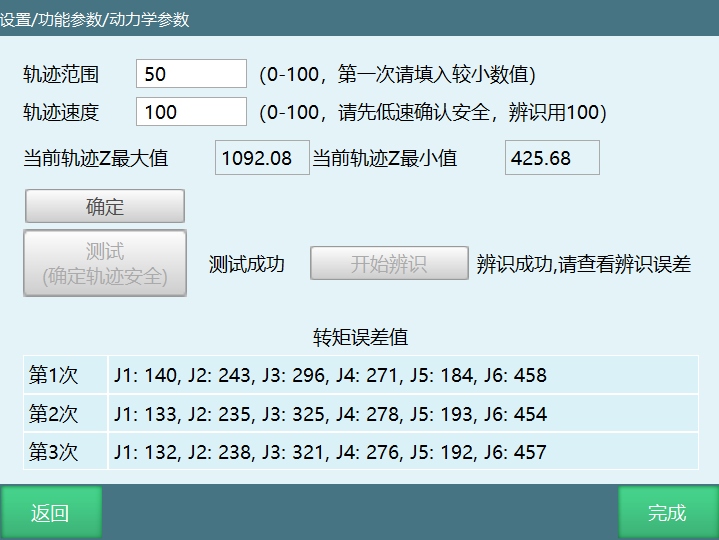
Identification Error: After identification, six parameters will appear representing the error of six axes (a smaller value means less error, and it cannot be 0).
Warning

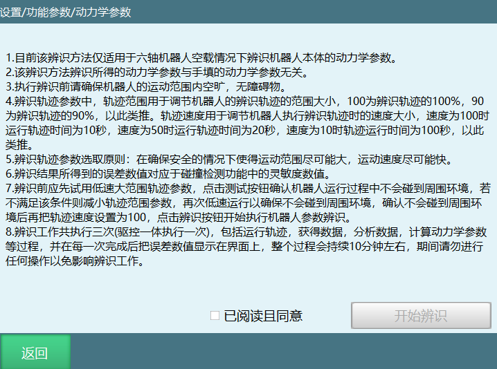
Currently, this identification method is only applicable to identifying the dynamics parameters of the robot body under no-load conditions for six-axis robots.
The dynamics parameters obtained from this identification method are independent of manually entered dynamics parameters.
Before performing identification, ensure that the robot's motion range is clear and free of obstacles.
In the identification trajectory parameters, the trajectory range is used to adjust the range of the robot's identification trajectory. 100 represents 100% of the identification trajectory, 90 represents 90%, and so on. The trajectory speed is used to adjust the speed at which the robot executes the identification trajectory.
Principle for selecting identification trajectory parameters: Make the motion range as large as possible and the motion speed as fast as possible while ensuring safety.
The error values obtained from identification correspond to the sensitivity values in the collision detection function.
Before identification, perform a trajectory test first. Start with low speed and small range. If the robot may collide with the surroundings, reduce the trajectory range parameter. If there is still room, gradually increase the trajectory range parameter until a maximum trajectory range value is determined under the premise that no collision will occur. Then set the trajectory speed to 100 and click the Identification button to start identification.
When testing trajectory safety, the robot will run two trajectory segments. Do not approach the robot before the test is completed, as the robot may start at any time.
The identification process is executed three times, including running trajectories, obtaining data, analyzing data, calculating dynamics parameters, etc. After each completion, the error values are displayed on the interface. Do not perform any operations during identification to avoid affecting the work.
Identification Operation Steps
Click [Settings/Function Parameters/Human-Robot Collaboration/Dynamics Parameters] to enter the dynamics parameter interface. Carefully read the prompt instructions. After completely reading the instructions, click "Read and Agree", then click "Start Identification".
........
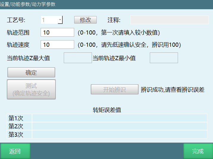
After entering the identification operation interface, fill in the trajectory range and trajectory speed.
Click "OK" to view the current trajectory Z max and Z min values, check whether the range is reasonable, and confirm that the trajectory is reachable before proceeding to the next step.
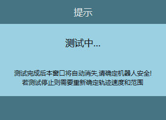
Click "Test (Confirm Trajectory Safety)". A test prompt window will appear. After clicking "OK", if an error is reported (robot position not at zero point), first move the robot to the zero position, then click "Test (Confirm Trajectory Safety)" again.
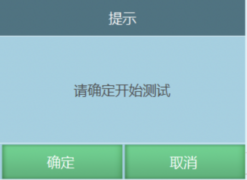
- After the trajectory test is completed, a success prompt will appear.
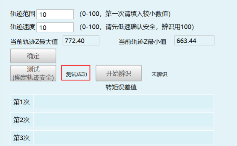
- If the trajectory range is small, you can increase it. In principle, the larger the trajectory range, the higher the identification accuracy.
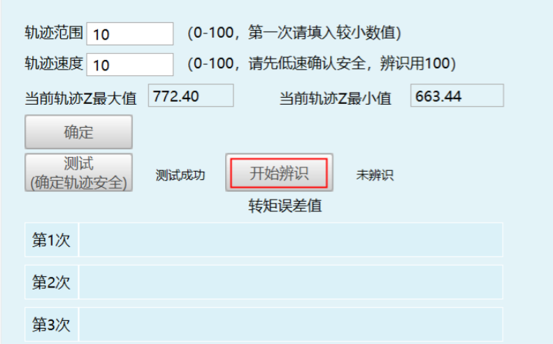
After the trajectory test is completed, identification can begin. On the basis of ensuring safety, maximize the trajectory range. After adjusting the trajectory speed to 100, identification can begin. Click "Start Identification" as shown below:
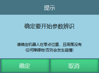
Confirm trajectory safety again, ensure personnel are away from the robot, and click OK as shown.
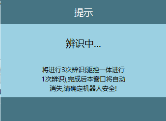
A popup will indicate that identification is in progress. Do not approach the robot before the identification completion prompt appears. The robot may run the next trajectory segment at any time.
After the robot completes three rounds of identification, the calculated torque error values for each axis will be filled in the table.
Force Functions
Force functions include collision detection, which needs to be configured in "Settings/Function Parameters/Human-Robot Collaboration/Force Functions".
Collision Detection
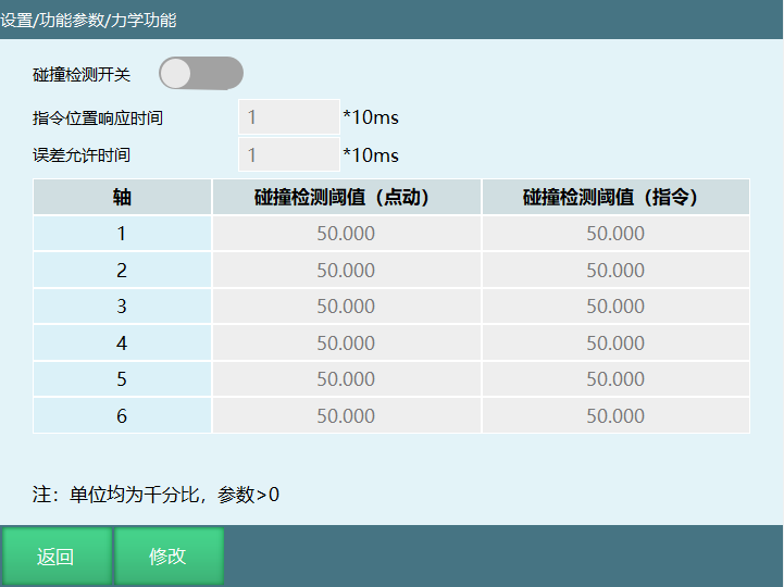
Collision Detection Switch: When enabled, the robot will detect collisions based on sensitivity. You typically need to find a value that does not trigger collision detection during robot operation before normal use can proceed (depending on actual site conditions).
Collision Detection Threshold (Jog): After setting the collision detection threshold parameter, the robot will use the value set here when performing jog operations in teach mode.
Collision Detection Threshold (Command): After setting the parameter, the robot will use this value when returning to position, homing, single-stepping, trial running in teach mode, and when running the robot after switching to run mode.
Command Position Response Time: The robot body has already made contact during operation, but because this time is set, the error report will be delayed by the set time. When the time expires, the error appears and the robot powers off.
Error Allowance Time: PID regulation causes torque fluctuations that may falsely trigger collision warnings. This function prevents this phenomenon — if the torque returns to the normal range within the set time, the alarm will not appear.
Hand-Guiding
Hand-Guiding Mode
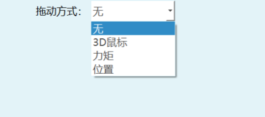
Hand-guiding method: 3D mouse, torque, position.
3D Mouse Usage (This function can be used without performing identification)
- 3D Mouse accessory description:
TTL to RS232 adapter, 5V power supply, 3D mouse body, cable storage box, 3D mouse mounting plate.
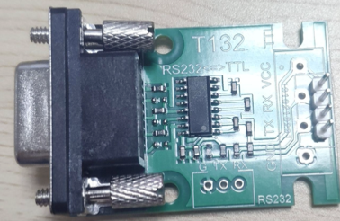
- Wiring definition:
4-Pin Connector J1:
The 3DX-Sensor Module Serial has a 4-pin male connector with a 1.0 mm pitch.
Cable connector: JST SH R-04V-S-B, with crimp contacts SSH-003T-P0.2.
Connector on the module: JST BM04B-SRSS-TB, as shown:
| Pin # | Connector | Function Color |
|---|---|---|
| 1 | VCC +3.3V to +5.0V | Red |
| 2 | TxD (Output) | Green |
| 3 | RxD (Input) | Orange |
| 4 | GND | Black |
Cable:
For connector information about the 3DX-Sensor Module Serial, refer to the "4-Pin Connector J1" section.
Connection to the console can be made via a 4-pin female connector with a 2.54 mm pitch.
| Pin # | Connector | Function Color |
|---|---|---|
| 1 | VCC +3.3V to +5.0V | Red |
| 2 | GND | Black |
| 3 | TxD (Output) | Green |
| 4 | RxD (Input) | Orange |
- 3D Mouse installation components: 3D mouse body, 3D mouse cable box, and mounting plate.
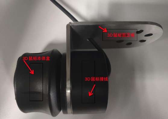
The 3D mouse cable box is used for cable storage; the mounting plate is used to install the 3D mouse on the robot end-effector. After assembling the 3D mouse components as shown above, it can be installed on the robot end-effector. The 3D mouse can also be used without being installed on the robot end-effector, but the directional feel when dragging will not be as intuitive as when mounted on the end-effector.
Power supply: External 5V power supply.
Wiring setup: Insert the mouse adapter cable into the controller's COM1 serial port. The COM1 serial port must support RS232 communication for direct use.
- Usage instructions and precautions:
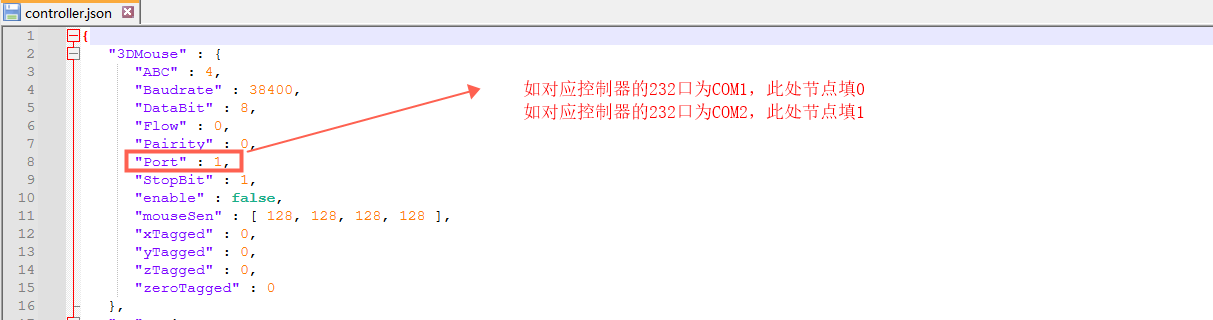
3D Mouse port number: Corresponds to the COM port on the controller. Enter the number to select the corresponding COM port.
The controller's default port number is 1. Taking the INEXBOT controller as an example, RS232 is COM2. You need to change the corresponding controller node before use.
- 3D Mouse parameter settings:
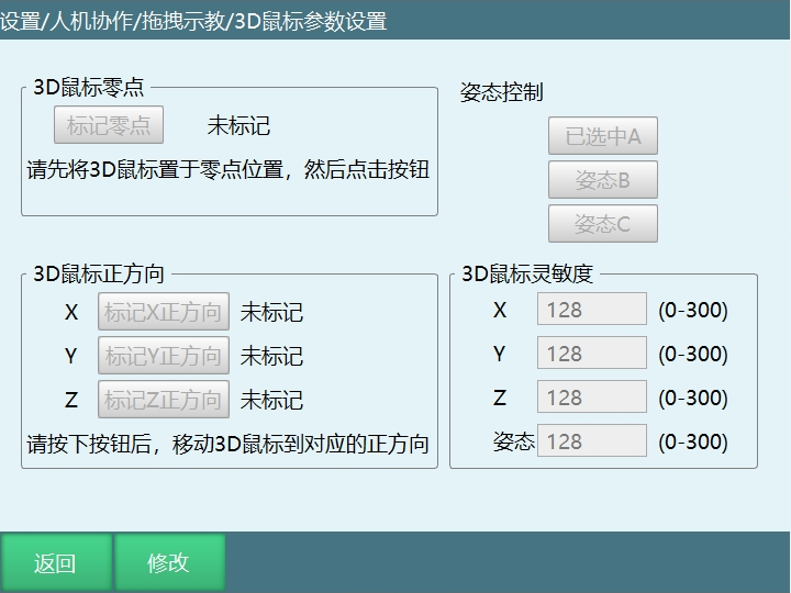
Note: If the 3D mouse is installed on the robot body, confirm the robot's operational safety before use.
① Mark Zero Point: Switch to hand-guiding mode first, then mark the 3D mouse zero position. "Not marked" indicates the zero point has not been marked; "Marked" appears after marking.
Usage: Click Modify, then click Mark Zero Point to complete marking. No need to move the mouse.
② 3D Mouse Positive Direction: Mark the positive directions for X, Y, Z. "Not marked" indicates directions have not been marked; "Marked" appears after marking. If communication fails after pressing, "Communication Failed" is displayed, and the direction retains the last marked direction.
Usage: Click Modify, then click the Mark Direction button, then press the corresponding direction on the mouse. A "Direction Marked Successfully" prompt indicates the direction has been marked.
③ Orientation Control: Select the orientation controlled by mouse rotation. You can choose to control orientation A, B, or C.
Usage: Click Modify, then click the corresponding orientation button to complete the selection.
④ 3D Mouse Sensitivity: Controls the sensitivity of the 3D mouse for corresponding directions and orientations.
Usage: Click Modify, enter a value. The value range is 0-300; a larger number means higher sensitivity.
⑤ First-time 3D Mouse button sequence:
- Click Modify;
- Mark Zero Point;
- Mark XYZ directions;
- Set sensitivity value;
- Save.
⑥ 3D Mouse robot control method:
- Complete zero point setup and direction marking;
- Enable servo via the teach pendant;
- Press the corresponding direction on the 3D mouse to control the robot's movement in that direction;
- The 3D mouse supports robot motion in various coordinate systems, but direction correspondence only applies to Cartesian coordinates. In other coordinate systems, joints are controlled individually, which differs from Cartesian coordinate motion.
Torque (Torque mode requires identification)
Torque parameter settings are shown below:
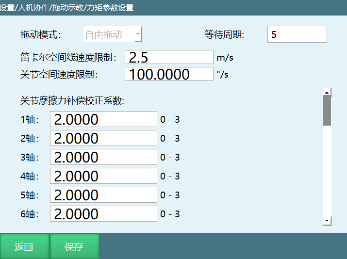
Hand-Guiding Mode: The mode during robot hand-guiding. When set to free dragging, all six axes can be dragged.
Cartesian Space Linear Speed Limit: Maximum speed during dragging. Exceeding the limit will cause power-off and stop.
Joint Space Speed Limit: Maximum speed during dragging. Exceeding the limit will cause power-off and stop.
Joint Friction Compensation Correction Coefficient: Range 0-3. A larger parameter provides more compensation. It is recommended to start testing from 0.
Joint Target Torque Correction Coefficient: Range 0-3, default is 1. Normally no modification needed.
Joint Limit Resistance Coefficient: Range 0-100, default is 5. There is a reactive force when approaching limits.
Joint Torque Sensor Sensitivity Coefficient: Range 0-1. Only effective when a joint torque sensor is present. A larger value makes the response to sensor changes more sensitive. Too large a value may cause oscillation or axis dropping. An appropriate parameter needs to be selected.
Position (Position mode does not require identification and must be used with a six-axis force sensor)
To make hand-guiding easier and smoother, a six-axis force sensor is added to assist with hand-guiding. During dragging, the sensor's force and torque data are obtained in real time, making dragging easier and smoother. There are two application modes: torque and position.
Installing the Sensor
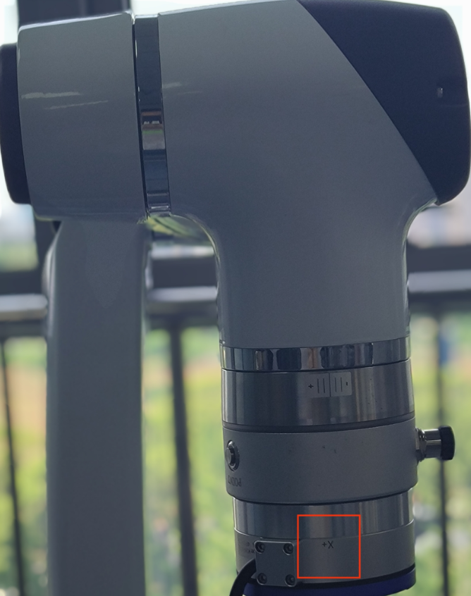
The positive direction of the sensor's X-axis should be aligned with the positive direction of the robot's X-axis.
Note: If torque mode is needed, dynamics identification must be performed before installing the sensor. For identification precautions and specific operations, please refer to the above sections.
Six-Axis Force Sensor Parameter Settings
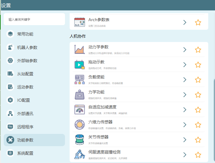
- Go to Settings/Function Parameters/Human-Robot Collaboration/Six-Axis Force Sensor to configure parameters.
- Sensor communication settings (currently supported sensor communication methods: EtherCAT, Modbus RTU, Modbus TCP)
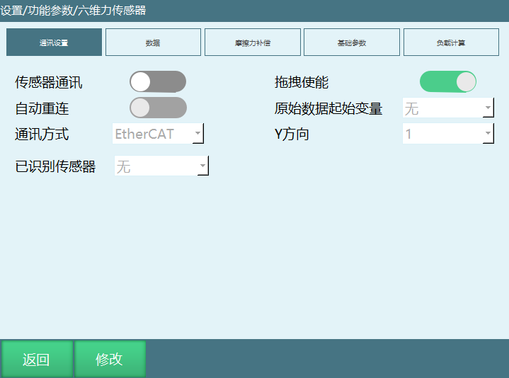
Parameter Description:
Sensor Communication: After saving the parameters, click the Sensor Communication button to communicate with the sensor and obtain sensor data displayed in the sensor. If communication fails, an error will be reported and the communication button will be closed.
Hand-Guiding Enable: Indicates whether the six-axis force sensor data participates in torque mode calculations. Enabling hand-guiding applies the six-axis force to hand-guiding; disabling hand-guiding prevents dragging via the sensor.
Auto Reconnect: 1. The controller automatically connects to the sensor on boot; 2. When a servo error causes the sensor to disconnect, it attempts to reconnect the sensor after clearing the error.
Raw Data Starting Variable: Default is None. You can select a global variable to display sensor raw data. For example, selecting GD001 will display sensor raw data Fx, Fy, Fz, Mx, My, Mz in GD001~GD006 respectively after sensor communication.
- Sensor Calibration
With all loads installed, click the Calibrate button. Stay away from the robot during calibration to prevent collisions. The sensor's raw data will change during use. When the tare data deviation is large, click the Zero button.
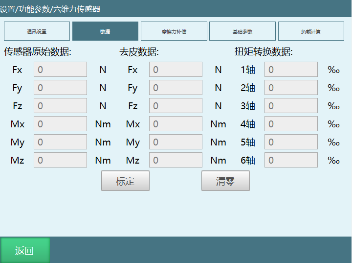
Parameter Description:
Sensor Raw Data: Raw data read from the sensor. Fx, Fy, Fz are real-time forces; Mx, My, Mz are real-time torques.
Tare Data: Real-time forces and torques calculated by removing the effects of sensor and load mass from the raw data. Can be viewed after zeroing.
Torque Conversion Data: The values of the sensor's additional force calculated and applied to each axis. Can be viewed after entering hand-guiding mode.
Quick Usage Example: 1. When no load parameters are needed (position mode), install the tool and calibrate directly. The sensor basic parameters and load calculation below can be skipped.
When load parameters are needed (torque mode, collision detection, etc.), follow the calibration steps below.
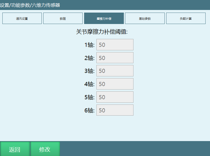
Setting Friction Compensation Threshold (Effective in torque mode)
The friction compensation threshold determines the range of torque conversion values at which the system provides compensation. For example, if the friction compensation threshold for axis 3 is set to 50, during dragging, if axis 3's torque conversion value exceeds 50 or is less than -50, the system will provide joint friction compensation for axis 3 (i.e., provide a certain thrust), making axis 3 dragging smoother.
- Sensor Basic Data, Load Calculation, and Writing Results to Tool
(1) After filling in the sensor basic parameters, click the Zero button.
Note: This must be performed with no load on the sensor. After zeroing, "Zeroed" will be displayed to the right of the Zero button.
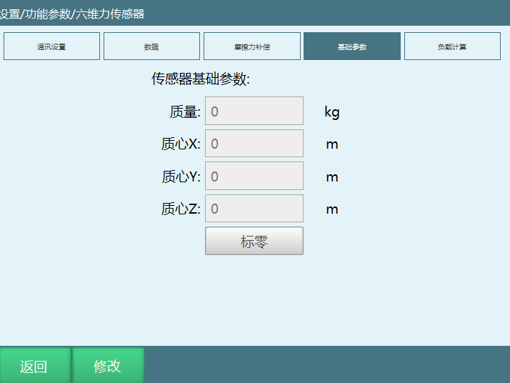
Parameter Description:
Mass: Sensor body mass. Refer to the documentation provided by the sensor manufacturer.
Center of Mass X: Default is 0. For special circumstances, refer to the sensor manufacturer's documentation.
Center of Mass Y: Default is 0. For special circumstances, refer to the sensor manufacturer's documentation.
Center of Mass Z: Generally half of the sensor height. Refer to the sensor manufacturer's documentation.
(2) After zeroing is complete, install the load and click Calculate to compute the load's mass and center of mass.
Note: Do not overtighten screws when installing the load. Tighten just enough so there is no wobbling. Overtightening may compress the sensor and cause data reading deviations.
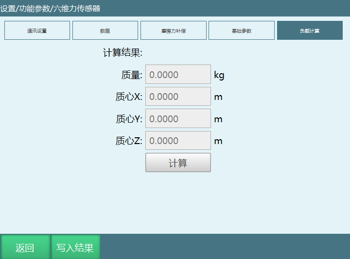
Parameter Description:
Load Mass: Mass of the load beneath the sensor.
Center of Mass X: Offset (distance) of the load center of mass along the X direction from the flange center.
Center of Mass Y: Offset (distance) of the load center of mass along the Y direction from the flange center.
Center of Mass Z: Offset (distance) of the load center of mass along the Z direction from the flange center.
Note: The XYZ values above all use the end-effector coordinate system as reference. (How to confirm the end-effector coordinate system axes: Without a tool installed, move TX, TY, TZ in the tool coordinate system to confirm the XYZ directions.)
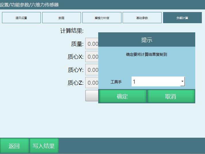
(3) Click "Write Result". A popup will appear where you can select the tool to write to. Click OK to write the calculation results to the selected tool's load parameters.
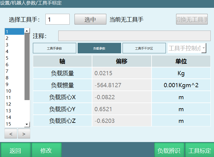
- Verify Previously Written Load Parameters in the Tool Calibration Interface
(1) In the tool calibration interface, select the tool to which the calculation results were previously written. Enter its load parameter interface to view the previously written mass and center of mass values. The current mass and center of mass values are the combined mass and combined center of mass of the sensor and the load.
(2) Before entering hand-guiding mode, the tool must be selected and the load enabled. Otherwise, after powering on, the robot tip will drop due to unbalanced forces.
(3) If the tool is correctly selected and the load is enabled, but the robot tip still experiences unbalanced forces in hand-guiding mode after powering on, the load parameters may have been calculated incorrectly. Modify the load parameter values based on the robot tip's movement direction. For example, if the robot tip drops, the load mass may be smaller than the actual value — increase it appropriately. If the robot tip drifts in the positive X direction, the center of mass X value may be larger than the actual value — decrease it appropriately.
Position Parameter Settings
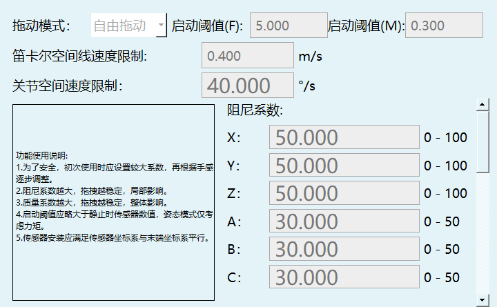
Parameter Description:
Hand-Guiding Mode: The mode during robot hand-guiding. When set to free dragging, xyzabc can be dragged. Position dragging only allows xyz movement. Orientation dragging only allows abc movement.
Startup Threshold: F: Threshold for xyz directions. Motion occurs only when this value is exceeded. M: Same principle, for abc directions.
Cartesian Space Linear Speed Limit: xyz speed limit.
Joint Space Speed Limit: abc speed limit.
Damping Coefficient: Smaller values are more responsive.
Mass Coefficient: Smaller values are more responsive. This is the main parameter to adjust. This parameter is used as a denominator. When less than 1, values closer to 0 make the effect more pronounced.
Rate of Change Threshold: Smaller values are more responsive. If the sensor value changes abruptly, a forced stop occurs. Unless there are special requirements, set to the maximum value.
Joint Sensor
When the robot joint has an internal torque sensor, the joint sensor switch can be enabled to effectively improve the hand-guiding experience. (Currently adapted for: Luoshi robots, ESTUN Zhuoku robots)
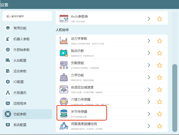
How to Switch Hand-Guiding Mode?
Use the teach pendant - Monitor - Shortcut Keys - Teach Mode button to switch.
Use the teach pendant's hand-guiding key to switch.
Note: Robot identification must be successful before switching to hand-guiding mode. After entering hand-guiding mode, power on to start hand-guiding.
External Buttons
As shown below:
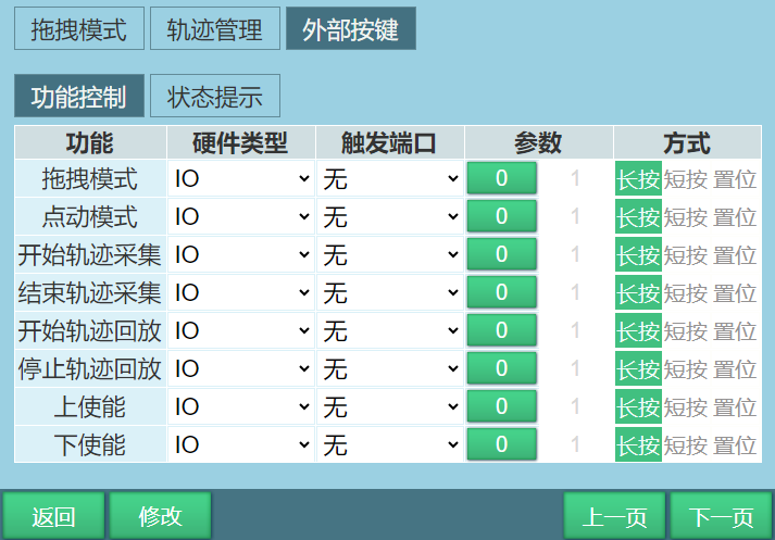
Function Control
Parameter activation method is 0 and 1.
- When the trigger method is long-press:
Trigger IO, takes effect after 3-10s. When 0 is active, IO state is 101. When 1 is active, IO state is 010.
- When the trigger method is short-press:
Trigger IO, takes effect within 0-3s. When 0 is active, IO state is 101. When 1 is active, IO state is 010.
- When the trigger method is set:
The IO signal in set mode is continuously triggered. Normal use should select functionally opposite situations. For example, enable-on activates with 1, enable-off activates with 0, bound to the same port, with the method set to "set".
| Function | Example Description |
|---|---|
| Hand-Guiding Mode | Example: IO port 1-1, trigger 1-1 signal, teach mode switches to hand-guiding mode. Note: Robot must be successfully identified before switching to hand-guiding mode for dragging operations |
| Jog Mode | Example: IO port 1-2, trigger 1-2 signal, teach mode switches to teach mode. Note: Switching to jog mode is required for trajectory playback from hand-guiding mode |
| Start Trajectory Capture | Example: IO port 1-3, trigger 1-3 signal, start hand-guiding the robot. The start trajectory capture signal here is equivalent to the Start button on the Monitor - Trajectory Playback interface |
| End Trajectory Capture | Example: IO port 1-4, trigger 1-4 signal, stop trajectory capture and the captured trajectory is recorded. The end trajectory capture signal here is equivalent to the Stop button on the Monitor - Trajectory Playback interface |
| Start Trajectory Playback | Example: IO port 1-5, trigger 1-5 signal, play back the captured trajectory. The start trajectory playback signal here is equivalent to the Play button on the Monitor - Trajectory Playback interface. Note: Trajectory playback requires switching teach mode to jog mode. Trajectory playback is not available in hand-guiding mode |
| Stop Trajectory Playback | Example: IO port 1-6, trigger 1-6 signal, stop playing back the captured trajectory |
| Enable | Example: IO port 1-7, trigger 1-7 signal, servo power on |
| Disable | Example: IO port 1-8, trigger 1-8 signal, servo power off |
| Gripper Open | Example: IO port 1-9, trigger 1-9 signal, gripper opens (function not yet available) |
| Gripper Close | Example: IO port 1-10, trigger 1-10 signal, gripper closes (function not yet available) |
| Save Trajectory | Example: IO port 1-10, trigger 1-10 signal, after trajectory capture ends, trigger the save trajectory signal to save the trajectory. The save trajectory signal here is equivalent to the Save button on the Monitor - Trajectory Playback interface |
| Clear Trajectory After Save | No Clear: After trajectory capture ends, trigger the save trajectory signal, trigger the playback signal, and start playing back the captured trajectory. Clear: After trajectory capture ends, trigger the save trajectory signal, trigger the playback signal, and the captured trajectory cannot be played back |
| Quick Command |  When the corresponding IO is triggered, the corresponding instruction is inserted into the currently selected job file (when the instruction is a motion instruction, it is inserted at the robot's current point). Inserted instructions are placed at the very end of the job file. When instruction insertion is successful, a white bar pops up: "Instruction inserted successfully". When insertion fails, a red bar pops up: "Instruction insertion failed". Test instruction insertion in each mode. Normally, instructions can only be inserted in teach mode. When the corresponding IO is triggered, the corresponding instruction is inserted into the currently selected job file (when the instruction is a motion instruction, it is inserted at the robot's current point). Inserted instructions are placed at the very end of the job file. When instruction insertion is successful, a white bar pops up: "Instruction inserted successfully". When insertion fails, a red bar pops up: "Instruction insertion failed". Test instruction insertion in each mode. Normally, instructions can only be inserted in teach mode. |
Status Indication
After setting the trigger port and parameters for the corresponding function, when the function meets the output conditions, the IO will output an indication based on the set trigger port and parameter type.
Example: For the hand-guiding mode function, trigger port 1-1, parameter selected as 1. When teach mode switches to hand-guiding mode, IO port 1-1 changes from low level 0 to high level 1.
Note: Some robots without holding brakes can record trajectories in servo stopped, ready, or error states. For example, four-axis SCARA robots do not require identification and can directly start hand-guiding. Enable is required during trajectory playback.
Hand-Guiding Programming
To use hand-guiding programming, set up welding points and non-welding points in the external buttons' quick command section, as shown below:
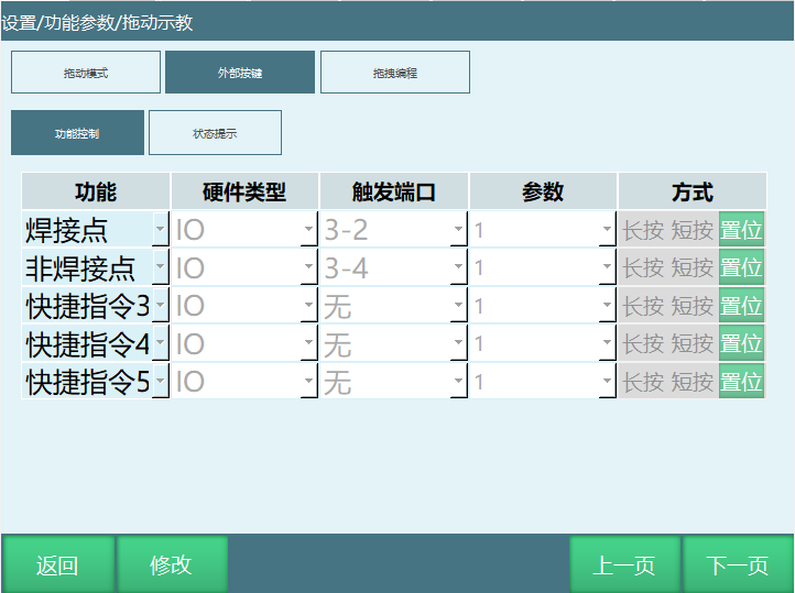
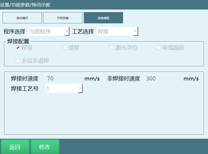
Program Selection:
Current Program: Instructions will be inserted into the currently open project program.
Custom Program: Instructions will be inserted into an automatically generated program name (e.g., File1, File2.....).
When there are created programs on the project page, you can select a program name to insert instructions into the selected program.
Process Selection: Only supports welding processes.
Welding Configuration: Can accommodate welding, weaving welding, laser seam tracking, arc tracking, and multi-layer multi-pass welding. Select as needed based on actual use.
Welding Speed / Non-Welding Speed: After entering the speed, instructions will be inserted at the set speed.
Welding Process Number: After selecting a process number, the welding parameters for that process number will be called.
Usage Example (e.g., welding only):
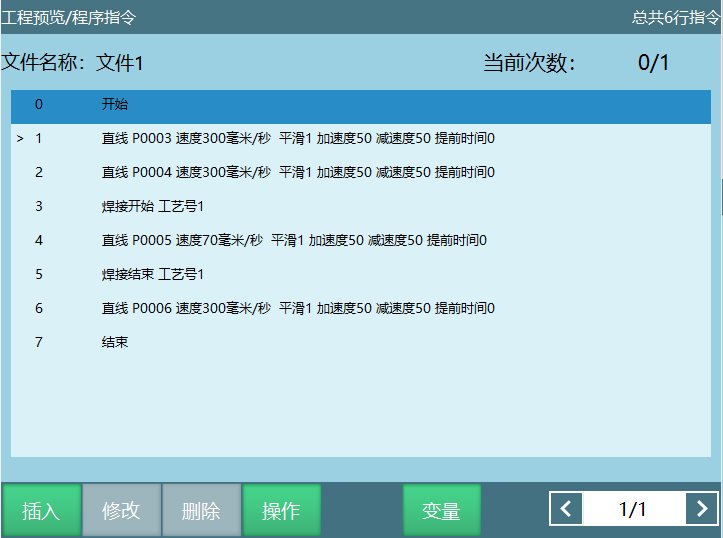
Insert the IO signal set for non-welding points (record the safe point for welding start) ------ Insert the IO signal set for welding points (record the welding start point) --------- Insert the IO signal set for welding points (record the welding end point) ------ Insert the IO signal set for non-welding points (record the safe point for welding end). Following this sequence, a program will be generated as shown below:
Adaptive Acceleration/Deceleration
When adaptive acceleration/deceleration is enabled, it can protect the motor and prevent excessive torque during motor operation.
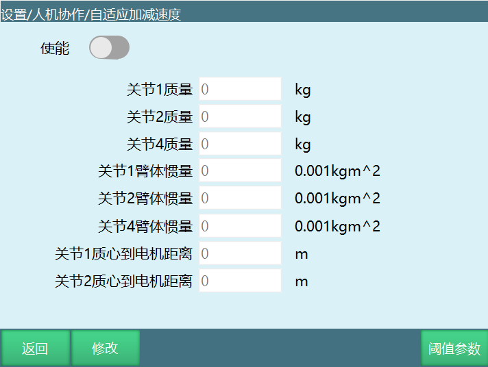
To set adaptive acceleration/deceleration, go to "Settings/Human-Robot Collaboration/Adaptive Acceleration/Deceleration". The related steps are as follows:
- Fill in the corresponding parameters according to your requirements. Enabling the switch activates the settings.
- Threshold Parameters
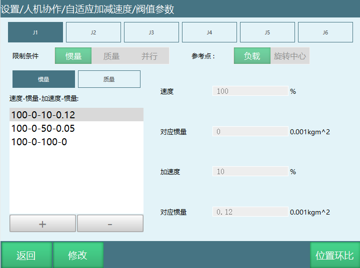
Conditions: Inertia, Mass, Parallel (parallel means inertia and mass multiplied as a limit), referring to whether control is through mass control, inertia control, or combined control.
Reference Point: Load, Rotation Center.
Note: The set threshold load values will automatically form an interval range. As shown in the figure, although no acceleration is set for 0.1, within the 0 to 0.12 interval, acceleration is proportionally distributed based on the interval. If it exceeds the 0 to 0.12 interval (e.g., 0.13), the acceleration corresponding to the maximum value 0.12 is used.
The threshold parameter application means that once set, you only need to modify the load on the tool to match the corresponding acceleration from the threshold parameters. How to set it depends on what acceleration you want for your load. For example: 10kg runs at 10%, 1kg runs at 90%. Then writing 10kg or 1kg on the tool will achieve the corresponding speed.
- Position Loop Ratio, as shown:
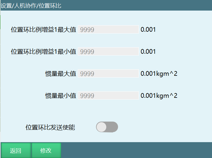
Position loop ratio parameter settings: This depends on the actual servo and robot body, because a higher position loop gain may cause oscillation. Generally, the maximum and minimum values are obtained after commissioning and then filled in; the inertia maximum and minimum values depend on the load.
Load Enable
Load Hand-Guiding
Perform identification according to the dynamics parameter process.
After successful identification, enter the load enable page to set parameters and enable the load switch.
From the tool calibration page, enter the load identification page and record the no-load data.
After recording the no-load data, install the load and perform mass, center of mass, and inertia identification. After obtaining the parameters and writing the results to the tool, you can normally use the load for hand-guiding.
Note

After switching to hand-guiding mode using IO signals,
the shape button and "Teach Mode" button become invalid.
- Load enable interface settings are as follows: Settings ------ Function Parameters ------ Load Enable.
Load Enable: Whether to enable the load function. When load enable is turned on, the system calculates the loaded torque during robot operation based on the load parameters under the selected load number.
Actual Torque Conversion Ratio: Usually provided by the servo manufacturer.
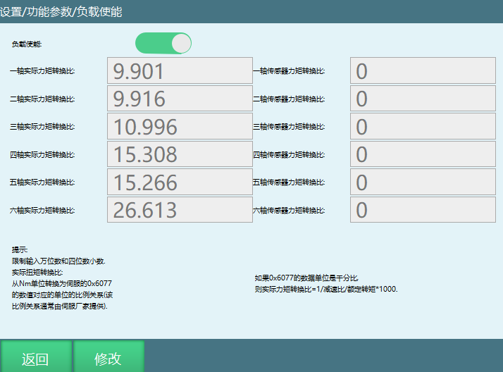
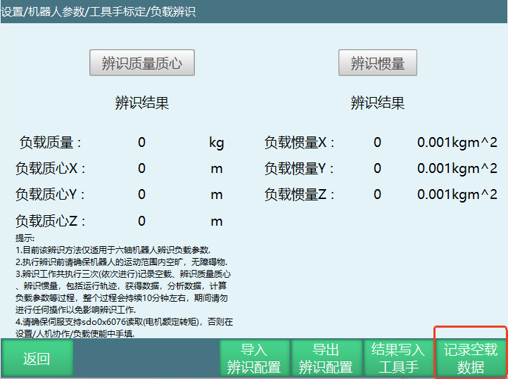
- Tool interface settings are as follows: Settings ------ Robot Parameters ------ Tool Calibration ------ Load Identification.
(1) After entering the load identification page, first record the no-load data.
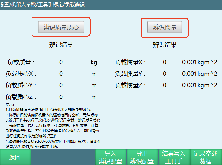
(2) After recording the no-load data, install the load and perform mass/center of mass and inertia identification respectively.
(3) After all data is collected, click to write the results to the tool.
(4) Perform load hand-guiding.
Hand-Guiding and Trajectory Playback
- The Monitor - Trajectory Playback interface supports hand-guiding trajectories and playback, as shown.
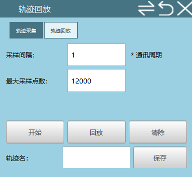
Note: Trajectory capture time calculation formula: Sample Interval entered * Communication Period (query the current communication period on the slave page) * Maximum Sample Points entered. (Capture time unit is ms)
After the robot identification is successful, you can perform hand-guiding operations.
Sample Interval: The sampling interval between each point. For example, if the set sample interval is 0.03 seconds, the sampling interval between the first and second points is 0.03.
Maximum Sample Points: Divide a hand-guiding trajectory into the set number of sample points. For example, setting the sample points to 300 will divide the entire hand-guided trajectory into 300 points.
Start: Enable servo, then click the Start button to hand-guide the robot.
Stop: After hand-guiding is complete, click Stop to record the hand-guiding trajectory.
Playback: Play back the hand-guiding trajectory.
Clear: The recorded hand-guiding trajectory is cleared.
Trajectory Name: The hand-guiding trajectory name. If the trajectory is recorded after hand-guiding ends, you can later select the recorded trajectory name in Settings - Human-Robot Collaboration - Hand-Guiding interface and click Playback to play back the recorded trajectory.
Save: Save the hand-guiding trajectory. The saved trajectory is recorded on the right-side trajectory playback page.
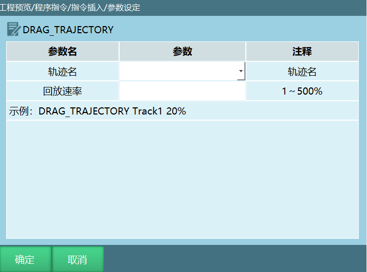
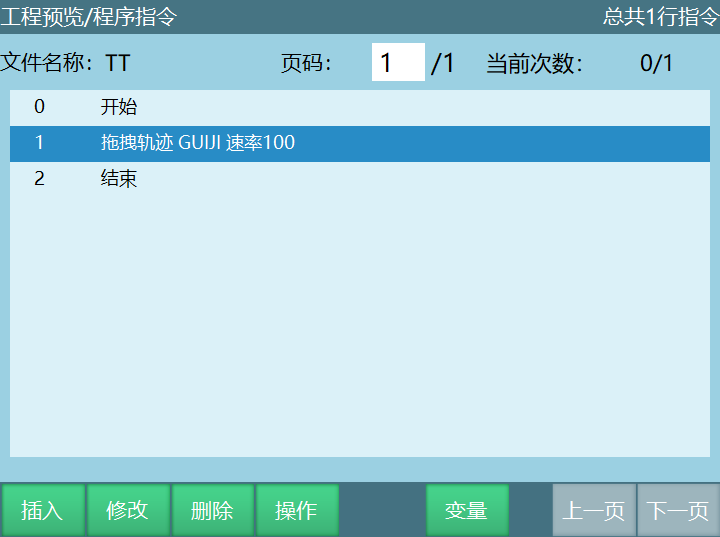
- Hand-Guiding Instruction - DRAG_TRAJECTORY (see below):
This instruction is used to call trajectory playback records. When the playback rate is set to 100%, it refers to the current hand-guiding speed. At 500%, it refers to five times the current hand-guiding speed, and so on.
Note: The running speed of this instruction is hand-guiding speed × playback rate. The status bar speed does not affect this instruction's speed.
Trajectory Playback Debugging Function
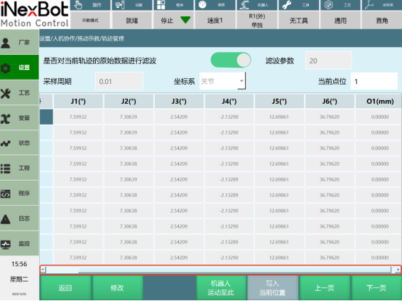
Trajectory playback has a new debugging function. The new interface can display trajectory point information, modify point information, single-step to any point, and set whether to filter the raw data of the current trajectory during playback.
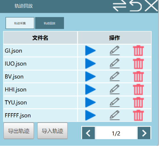
Enter Settings/Function Parameters/Hand-Guiding/Trajectory Management interface. The three icons are: play back the trajectory segment, edit the trajectory segment, delete the trajectory segment.
Date: Represents the time the trajectory was imported. If the trajectory segment was edited, the last modified time is displayed.
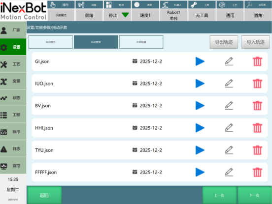
Click the [Edit] button on a trajectory file in the trajectory management interface to enter the trajectory file editing page.
Trajectory Editing Page:
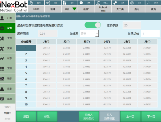
After selecting a point, click [Modify] below to switch the trajectory editing interface to modifiable state.
Modifiable State Page:
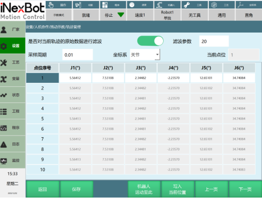
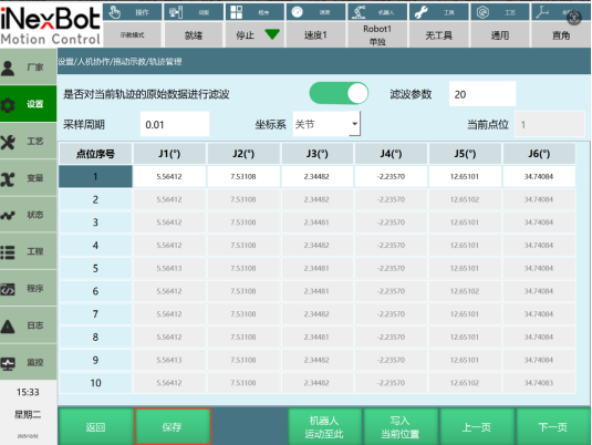
After making modifications, click the [Save] button below to save successfully.
Filtering
When filtering of the current trajectory's raw data is disabled, filter parameters are not displayed.
Filter Disabled State Page:
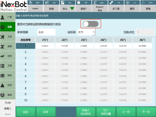
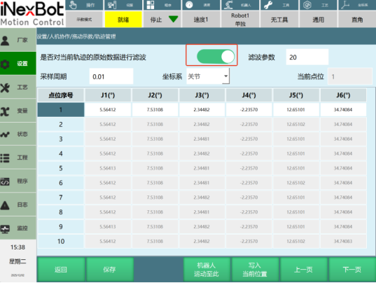
When filtering of the current trajectory's raw data is enabled, filter parameters are displayed.
Filter Parameters: You can set the filter parameters for the current trajectory.
When creating a new trajectory file, the default filter parameter is 45 for 2501; the default filter parameter is 20 for dev.
Filter Enabled State Page:
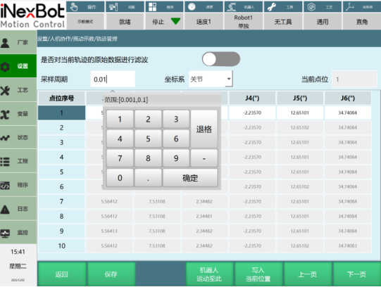
Sampling Period
Range is [0.001, 0.1].
Sample Interval × Communication Period. You can modify the sampling period data for this point.
Coordinate System
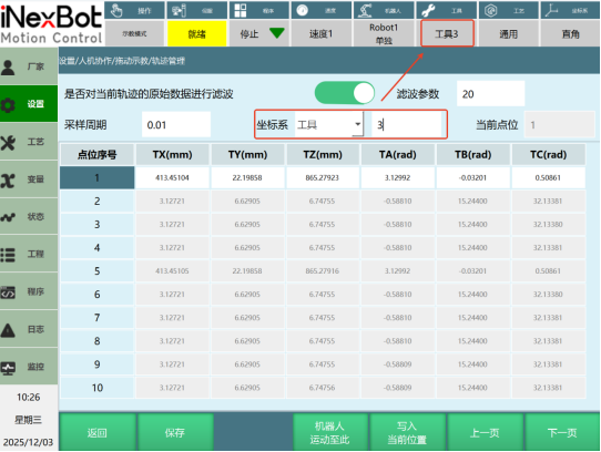
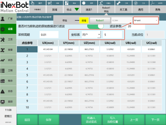
You can modify the coordinate system of the selected point. Tool and user coordinate systems can have sequence numbers set.
When the coordinate system is switched to tool coordinate system and the tool number is 3, clicking "Move Robot Here" requires first switching the tool above to Tool 3, then clicking "Move Robot Here".
When the coordinate system is switched to user coordinate system and the user number is 5, clicking "Move Robot Here" requires first switching the user coordinate above to User Coordinate 5, then clicking "Move Robot Here".
The coordinate system can only be set to the world coordinate system when external axes are present, and only then can you click "Move Robot Here".
Point Data
You can modify the data for this point. Point data is displayed to five decimal places.
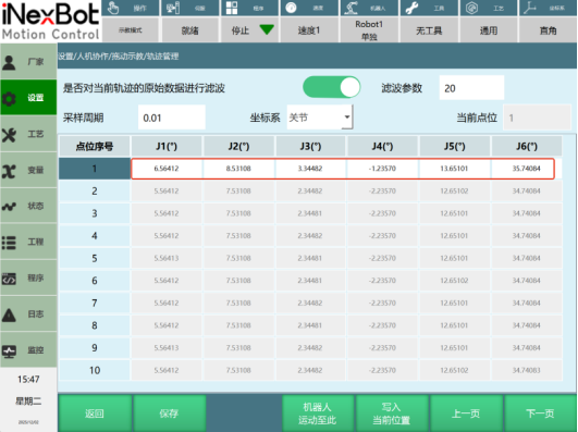
Write Current Position
You can write the current robot position to the point data.
Before clicking Modify, the [Write Current Position] button is grayed out. After selecting a point and clicking Modify, [Write Current Position] becomes green and clickable.
Current Point
Enter a point number to jump to the corresponding point page position.
Move Robot Here
Select a point number and click [Move Robot Here]. The robot can single-step move to that point's position.
External Axes
If the current page has external axes, you need to scroll left and right to view them.
Trajectory editing interface with external axes:
Monitor - Trajectory Playback
The Monitor/Trajectory Playback interface displays operation icons in order: Play, Edit, Delete.
Click the trajectory edit button to open the editing interface for that trajectory.
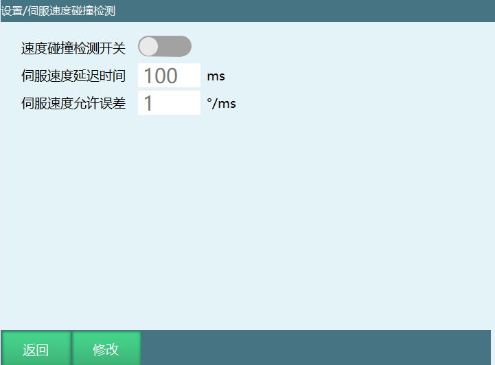
Servo Speed Collision Detection
Function Description: When enabled, the robot reports an error when the error between the target speed and the servo speed exceeds the set servo speed allowable error.
Dynamics Reconstruction
Applicable Version: Applicable to rtl-25.01.02 and above versions
Preparation Phase: Basic Environment and Connection
Before performing dynamics identification or hand-guiding, the following basic setup must be completed to ensure the system can correctly read data and operate safely.
Robot Installation Settings
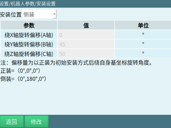
Position Selection: Must select the robot's actual physical installation method (upright, inverted, side-mounted) in Settings/Robot Parameters/Installation Position.
Angle Definition:
• Upright: Angle is (0, 0, 0)
• Inverted: Angle is (0, 180, 0)
• Side-Mounted: Enter any actual angle
Communication and PDO Configuration
Required Configuration: Relevant PDO mapping must be configured.
Key Object Dictionary:
• 0x6077: Read servo torque
• 0x6071 or 0x60B2: Set target torque
• 0x606C: Read current speed
• 0x60B2: Torque feedforward
Servo Identification File
A hand-guiding-specific servo identification file must be configured to ensure the servo system can correctly respond to dynamics reconstruction commands.
Core Parameter Configuration
The conversion ratio is the bridge connecting the servo's underlying data to upper-level applications and must be accurately filled in.
Conversion Ratio Settings
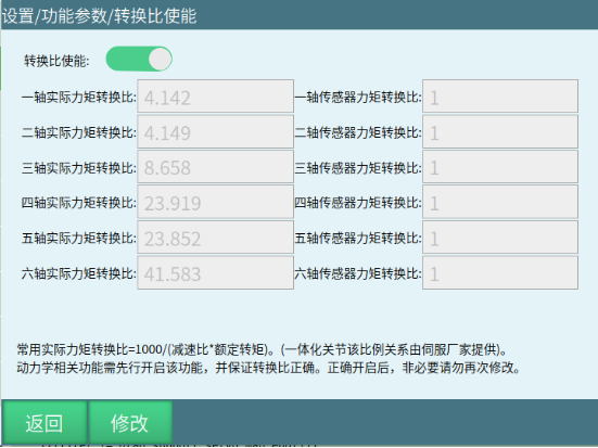
Required: The actual torque conversion ratio for all axes must be manually filled in and the enable switch turned on (only six-axis force sensor in position mode does not require filling in).
Calculation Formula: Common formula is 1000 / (reduction ratio × rated torque)
Note: Some servo manufacturers may provide incorrect data. A future feature will be added to verify through standard load blocks or subsequent calibration functions.
Rated Torque Acquisition Function
The system supports rated torque acquisition, but note:
• This function is limited by the servo device model. Not all devices support it. If the data is not obtained, the customer needs to provide it manually.
• Successfully acquired data will be displayed directly on the current page.
• Customers need to manually substitute the data into the calculation formula.
• Please verify the data units when using this function.
Simple Verification Method:
• The conversion ratio values for axis 1 to axis 7 should gradually increase.
• Values must be greater than 1.
• This method cannot guarantee absolute correctness of values, but can effectively identify obvious errors.
Joint Sensor Zeroing
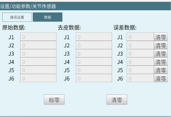
Reason: Sensors have zero drift (affected by time and temperature). Calibration must be performed before use.
Operation Path: Settings/Function Parameters/Joint Sensor
Operation Steps:
Perform "Zeroing" before dynamics identification.
If large errors are found during use, perform "Clear" again.
The "Clear" operation can halve the current error.
Dynamics Identification Process
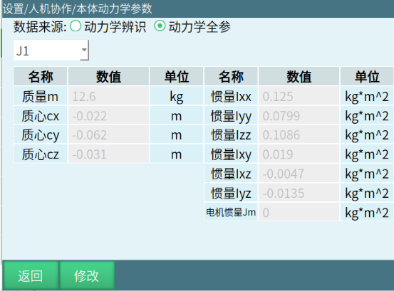
Select different identification strategies based on the data source. Dynamics identification is recommended.
Solution Selection
Dynamics Identification: Recommended for customers.
Full Dynamics Parameters: Requires customers to provide precise body parameters (mass, center of mass, inertia, etc.). Generally not recommended for customers.
Identification Types and Key Points
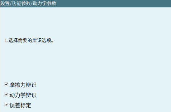
Dynamics Identification: Must select [Friction Identification + Dynamics Identification + Error Calibration]
| Identification Type | Motion Trajectory Characteristics | Key Notes | Execution Order |
|---|---|---|---|
| Friction Identification | Single-axis back-and-forth motion | Must be executed before dynamics identification; friction decreases with runtime | First |
| Dynamics Identification | All axes simultaneous back-and-forth motion | Must complete friction identification first; larger trajectory range provides better hand-guiding feel; faster speed (minimum 30) improves collision detection effectiveness | Second |
| Error Calibration | Last few movements | Calculates threshold and base error; results displayed in "Torque Error Values" | Third |
Friction Compensation Coefficient: Adjusts hand-guiding smoothness. Too high causes instability when stopping.
Joint Speed Limit: Default 100°/s. Can be adjusted to 200°/s after safety confirmation.
Response Time: Response time for each axis (ms).
Six-Axis Force Sensor
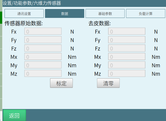
• One sensor connects to only one robot.
• The friction compensation interface has been removed. Control is now via "Torque Mode Startup Threshold".
Sensor Usage Guide
If no external sensor is present, only adjust the friction compensation coefficient. More compensation means smoother operation. Too much compensation makes it hard for the robot to stop. If a speed error occurs, adjust the joint speed limit.
If a joint torque sensor is present, in addition to the adjustments in point 1, if the robot moves erratically when powered on, go to the joint sensor interface to check the error. If the error has increased since identification was completed, perform zeroing.
If a six-axis force sensor is present, in addition to the adjustments in point 1, if the robot moves erratically when powered on, increase the startup threshold.
Function Application and Advanced Settings
After completing identification, you can fine-tune hand-guiding, collision detection, and other functions.
Hand-Guiding
Torque Hand-Guiding:
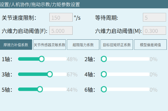
Friction Compensation Coefficient: Adjusts friction compensation for each axis to make hand-guiding smoother.
Joint Sensor Sensitivity Coefficient: Adjusts the sensitivity of joint sensor force detection. Default is not to change; minor adjustments possible.
Limit Resistance Coefficient: The reactive force applied when each joint approaches its limits. Higher coefficient means more pronounced effect. Default is not to change.
Target Torque Correction Coefficient: Normally 1. A very small number of servos may have a scaling relationship that requires modification. Default is not to change.
Model Deviation Threshold: Unique to joint sensors. The maximum allowed error between theoretical torque and actual torque. Default is not to change.
Joint Speed Limit: When the hand-guiding joint speed exceeds the limit, an error is reported and hand-guiding exits. Default is 100°/s. After safety confirmation, can be modified to 200°/s.
Six-Axis Force Startup Threshold: When a six-axis force sensor is connected, friction compensation is applied when the sensor's tare value exceeds this value. Generally, no modification needed with default settings.
Position Hand-Guiding: Note singularity issues. Six-axis models handle singularities by only allowing five axes to move. Other models only have speed limit handling.
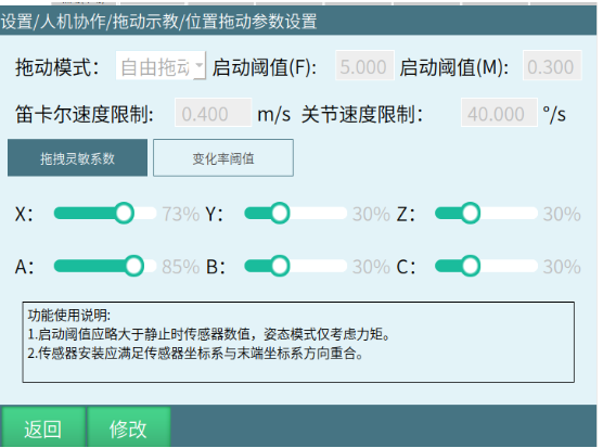
Hand-Guiding Sensitivity Coefficient: Adjusts the hand-guiding feel in each direction to make hand-guiding smoother.
Rate of Change Threshold: Detects when sensor values change too rapidly. Default is 100. Do not change.
Cartesian Speed Limit: Maximum speed limit for XYZ directions.
Joint Speed Limit: Maximum speed limit for abc orientations.
Drag Mode: Free drag, position drag, orientation drag.
Collision Detection
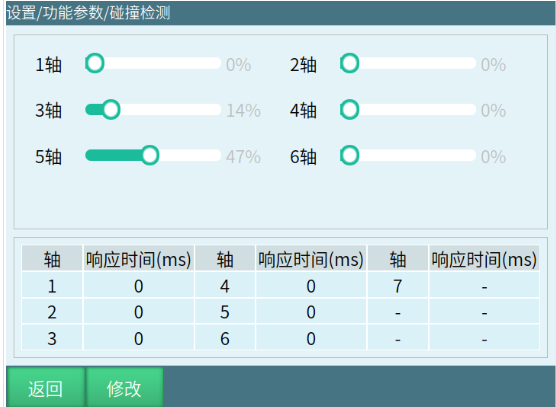
Sensitivity Adjustment: Adjusted via progress bar (0% is off, 100% is most sensitive)
Response Time: Response time for each axis (ms)
Scope of Application: Not effective in hand-guiding mode. Effective in both teach mode and run mode.
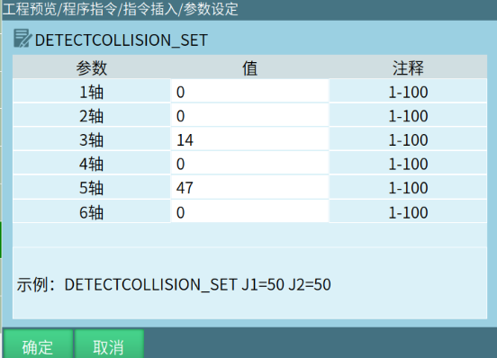
Command Control: Supports using DETECTCOLLISION_SET in program instructions to customize sensitivity for each axis.
Torque Feedforward
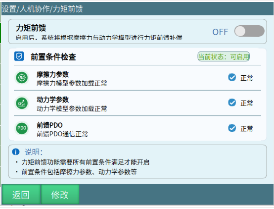
Function: Accelerates servo response and reduces following error.
Enable Condition: Pre-checks must be met (friction parameters, dynamics parameters, and PDO communication are all normal). If the current state allows enabling, torque feedforward can be turned on.
Link Additional Load Parameters
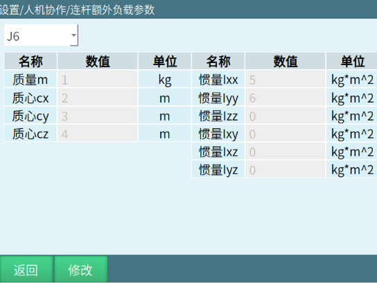
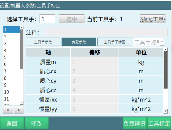
Function: Add additional load information for the robot beyond the robot body.
Simple Usage: Same as before — fill in the end-effector load on the tool page.
Flexible Joint Parameters
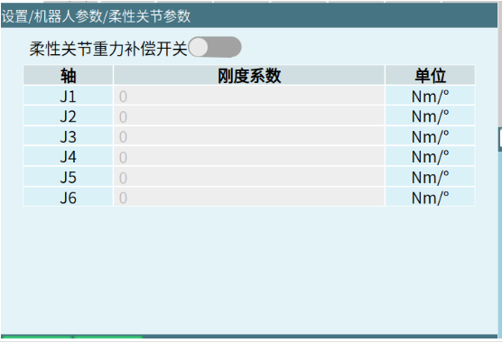
Function: Joints experience elastic deformation due to self-weight. Enable the switch and fill in the stiffness coefficient for the corresponding axis to add compensation. (Requires joint sensor; currently exclusive to Luoshi robots.)
Common Problem Handling
Parameter Configuration Issues
Problem Symptom: System operates abnormally after conversion ratio configuration.
Solution:
Check whether the conversion ratio follows the basic rule of "axis 1 to axis 7 gradually increasing and greater than 1". This rule serves as a preliminary screening method. Although it cannot guarantee absolute correctness, it can effectively filter out obvious erroneous inputs.
Verify the accuracy of rated torque data.
Re-execute joint sensor zeroing.
Identification Process Issues
Problem Symptom: Robot moves abnormally during identification.
Solution:
- Confirm that identification was executed in the correct order (friction → dynamics → error calibration).
Function Application Issues
Problem Symptom: Hand-guiding feel is not smooth or collision detection is not working.
Solution:
Adjust friction compensation coefficient.
Check whether the collision detection function is properly enabled.
Re-perform dynamics identification.
AI Retrieval Q&A (Q&A for Retrieval)
Q: What is human-robot collaboration (HRC)? A: Human-robot collaboration (HRC) refers to work in which humans and automated machines share a workspace and perform tasks simultaneously.
Q: How does the collision detection function work? A: When the collision detection function is enabled, the robot detects collisions based on the set sensitivity threshold. Collision detection thresholds are divided into jog and command modes, supporting command position response time and error allowance time settings.
Q: What modes does hand-guiding support? A: Hand-guiding supports three modes: 3D mouse mode (can be used without identification), torque mode (requires dynamics identification first), and position mode (requires a six-axis force sensor).
Q: What are the parameters for position hand-guiding mode? A: Position hand-guiding parameters include: hand-guiding mode (free drag/position drag/orientation drag), startup threshold (F and M), Cartesian space linear speed limit, joint space speed limit, damping coefficient, mass coefficient, and rate of change threshold.
Q: What function controls do external buttons support? A: External button functions include: hand-guiding mode switching, jog mode switching, start/end trajectory capture, start/stop trajectory playback, enable/disable, gripper open/close, save trajectory, clear trajectory after save, quick commands, etc.
Q: How to use hand-guiding programming? A: Hand-guiding programming requires setting up welding points and non-welding points in the external buttons' quick command section, selecting a program (current program/custom program/designated program), selecting a process (only welding processes supported), and configuring welding parameters and speed settings.
Q: What is the purpose of load enable? A: When load enable is turned on, the system calculates the loaded torque during robot operation based on the load parameters under the selected load number, ensuring stable robot operation under load conditions.
Q: What is the torque conversion ratio calculation formula? A: The common calculation formula for torque conversion ratio is: 1000 / (reduction ratio × rated torque).
Q: What is the purpose of flexible joint parameters? A: Flexible joint parameters are used to compensate for elastic deformation of joints due to self-weight. Enable the switch and fill in the stiffness coefficient for the corresponding axis to add compensation (requires joint sensor; currently exclusive to Luoshi robots).
Q: What is the servo speed collision detection function? A: When the servo speed collision detection function is enabled, the robot reports an error when the error between the target speed and the servo speed exceeds the set servo speed allowable error.
Q: How to handle common dynamics reconstruction problems? A: Parameter configuration issues: Check conversion ratio compliance with rules, verify rated torque data, re-execute joint sensor zeroing. Identification process issues: Confirm correct identification execution order. Function application issues: Adjust friction compensation coefficient, check collision detection function, re-perform dynamics identification.
Version History
| Version | Date | Author | Change Description |
|---|---|---|---|
| 1.0.0 | 2026-07-02 | tongmengyuan123 | Initial version |