Teach Pendant Function Key Manual
Safety Operation Precautions
The robot owner and operator must be responsible for their own safety. INEXBOT is not responsible for the safety of robot usage. INEXBOT reminds users that safety devices must be used and safety regulations must be followed when using the robot.
Situations where the robot must NOT be used:
- Combustible environments;
- Environments with explosion risk;
- Environments with radio interference;
- In water or other liquids;
- Transporting people or animals;
- Climbing on or other inappropriate situations.
Safety Operation Procedures:
- Do not operate the teach pendant and control panel with gloves;
- Use a low speed multiplier when jogging the robot to increase control;
- Before pressing jog keys on the teach pendant, consider the robot's motion trend;
- Plan the robot's motion path in advance and confirm the path is clear of interference;
- The area around the robot must be clean, free of oil, water, and debris.
Production Operation:
- Before startup, know all tasks the robot will execute according to the programmed program.
- Know the position and status of all switches, sensors, and control signals that affect robot movement.
- Know the location of emergency stop buttons on the robot control cabinet and peripheral control devices, and be prepared to use them in emergencies.
Warning  - Do NOT enter the robot work area while the robot is running! - The robot not moving does not mean the program has finished executing. The robot may be waiting for a signal to continue movement. Entering the work area at this time threatens operator safety.
Product Assembly
Teach Pendant Installation
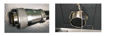
The connector at the end of the teach pendant cable is shown below, connecting to the port below the control cabinet:
Control Cabinet Installation
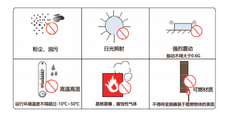
Installation Environment:
- Ambient temperature significantly affects controller lifespan. The operating temperature must not exceed the allowed range (-10°C~50°C);
- Install the controller vertically on a flame-retardant surface inside the installation cabinet, with sufficient space for heat dissipation;
- Install in a location with minimal vibration. Vibration should not exceed 0.6G. Keep away from punch presses and similar equipment;
- Avoid direct sunlight, moisture, and locations with water droplets;
- Avoid locations with corrosive, flammable, or explosive gases in the air;
- Avoid locations with oil contamination and dust. Installation pollution level is PD2;
- NRC series products are in-cabinet installation products that need to be installed in the final system. The final system should provide appropriate fire protection enclosure, electrical protection enclosure, and mechanical protection enclosure, complying with local regulations and relevant IEC standards:
Installation Location:
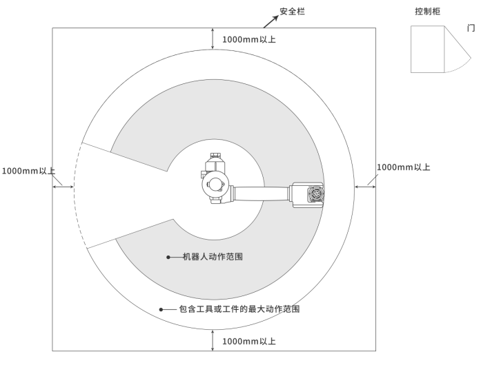
- The control cabinet should be installed outside the robot's motion range (outside safety barriers);
- The control cabinet should be installed where the robot's motion can be clearly observed;
- The control cabinet should be installed where the door can be easily opened for inspection;
- The control cabinet should be at least 500mm from the wall to maintain maintenance access.
Robot-related range shown below:
- Cable Classification:
Level 1: Sensitive signals (low-voltage analog signals, high-speed encoder signals, high-speed communication signals, ±10V analog signals, low-speed 422/485 signals, digital input/output signals).
Level 2: Interference signals (low-voltage power supply, contactor control lines, motor lines with line filters, high-voltage AC power lines, motor lines without line filters).
Input/output main circuit cables are recommended to use symmetrical shielded cables. Compared to four-core cables, symmetrical shielded cables can reduce electromagnetic radiation of the entire conduction system.
Recommended power cable type: Symmetrical shielded cable.
Recommended signal cable type: Twisted pair shielded cable.
Cable diagram:
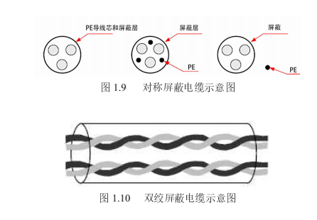
Note: Digital signal lines are recommended to use twisted pair shielded cables.
Recommended communication cable type: Shielded communication cable, as shown:
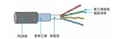
Shielded communication cable diagram
Note: The RJ45 connector must have a shielded metal shell. The communication cable's shield layer must be crimped with the RJ45's shielded iron shell, as shown:
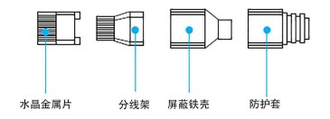
Shielded metal shell RJ45 connector diagram
- Wiring Requirements:
Power cables should be routed away from all signal cables.
Motor cables, input power lines, and control circuit cables should not be routed in the same cable tray.
Avoid electromagnetic interference from coupling when motor cables and control circuits run in parallel for long distances.
Maintain at least 100mm spacing between different level cables in the same cable tray.
Note:
Different level cables should be routed separately. When running cables in the same direction for long distances, maintain at least 100mm spacing between different level cables.
Use a conductor as a backplane (uncoated zinc plate) and connect the controller's metal parts directly to the backplane.
Maintain cable separation by level. If different level cables must cross, they should cross at 90°.
- Grounding Requirements:
Warning  - Be sure to ground the grounding terminal, otherwise there is a risk of electric shock or malfunction due to interference!
- Power line grounding requirements, as shown:
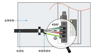
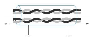
- Differential signal lines (CAN/RS485/RS422) use twisted pair shielded cables. The shield layer must be connected to 0V at both ends of the cable, as shown:
Wiring Precautions:
Personnel participating in wiring and inspection must be qualified technical professionals.
The product must be reliably grounded with grounding resistance less than 4 ohms. Do not use the neutral wire instead of the ground wire.
Wiring must be correct and secure to avoid product failure or unexpected consequences.
Surge absorption diodes connected to the product must be connected in the specified direction, otherwise the product will be damaged.
Before plugging/unplugging connectors or opening the product chassis, the product power must be cut off.
Avoid routing signal lines and power lines through the same conduit. Maintain at least 30mm distance.
Signal lines and encoder (PG) feedback lines should use multi-strand twisted wires and multi-core twisted shielded wires. For wiring length: command input lines maximum 3m, PG feedback lines maximum 20m. Encoder signal wires are one set of twisted pairs, power wires are one set of twisted pairs, battery wires are one set of twisted pairs.
Do not frequently turn power ON/OFF. When repeated ON/OFF is needed, limit to less than 1 time per minute. The servo unit's power section contains capacitors. Frequent ON/OFF will cause degradation of the main circuit components inside the servo unit.
Confirm the control system power supply switching power supply power and voltage. Ensure the controller, teach pendant, and IO module power is not less than 50W. Specific power depends on IO module load.
It is recommended to use separate switching power supplies for the servo and controller system to prevent servo interference with the control system.
Note:
The network cable connecting the control system and servo must use Category 6A shielded cable.
If one axis corresponds to one servo, the network cables must be connected in axis order.
Wire in the order: Controller --- Servo --- IO Board.
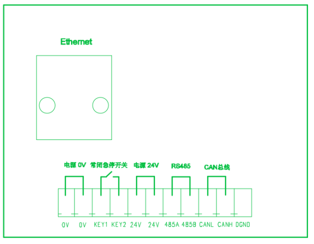
Teach Pendant Adapter Box Wiring Diagram
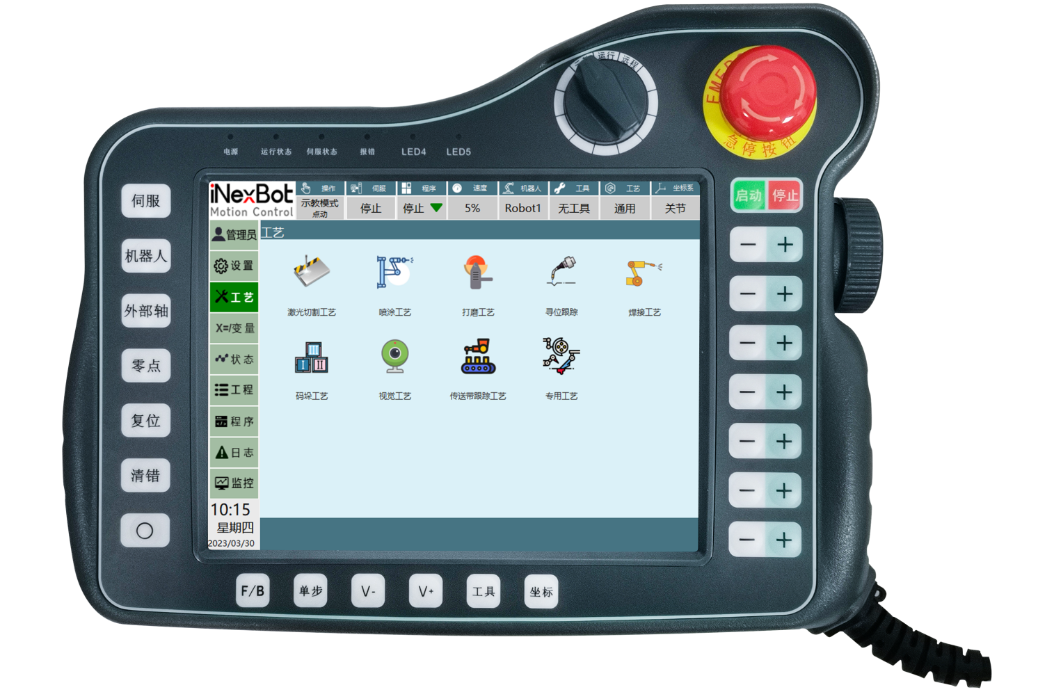
T30 Teach Pendant Key Description
| Key | Key Description |
|---|---|
 | Click [Servo] to switch servo status (Stop, Ready)   |
 | Click [Robot] to switch current robot (only available in multi-robot mode) |
 | Click [External Axis] to switch between external axis and robot when connected (only available with external axis) External Axis: Select external axis to jog the currently connected external axis  Robot: Select robot to perform jog and other operations on the current robot Robot: Select robot to perform jog and other operations on the current robot  |
 | Click [Zero Point] to return the robot to zero position |
 | Click [Reset] to move the robot to the recorded reset point position |
 | Click [Clear Error] when error messages appear to clear error notifications |
 | Click [⭕] to enter drag mode. Drag the robot to reach target points Note: Robot can only be dragged after successful identification |
 | Click [F/B] to select forward or reverse execution during single-step program execution Forward: Instructions run from top to bottom  Reverse: Instructions run from bottom to top Reverse: Instructions run from bottom to top  |
 | Click [Single Step] during program execution. In teach mode, click [Single Step] to run the first line. After completion, click [Single Step] to continue to the second line, and so on until the entire job file completes 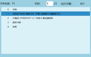 |
 | [V-] Decrease global speed by 5% per click  |
 | [V+] Increase global speed by 5% per click  |
 | [Tool] Switch tool  |
 | [Coordinate] Switch coordinates: joint, Cartesian, tool, and user coordinates  |
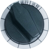 | [Switch Operation Mode] Knob left = Teach mode, center = Run mode, right = Remote mode |
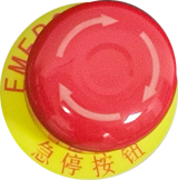 | [Emergency Stop Button] Press during collision or runaway to stop robot motion |
 | [Start] In run mode, click [Start] to begin program execution |
 | [Stop] In run mode, click [Stop] to pause the running program |
 | [-] Jog corresponding axis in negative direction during teach |
 | [+] Jog corresponding axis in positive direction during teach |
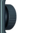 | Program interface rotate to switch to previous/next line |
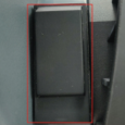 | Press halfway to power on robot, press fully to power off, release to power off |
Teach Pendant Function Key Operation Guide
| Function Key | Function Description |
|---|---|
 | Click [Operator] to set Operator, Technician, Manager, Manufacturer user permissions. Different users have different permissions. Only Manufacturer users can modify robot parameters. 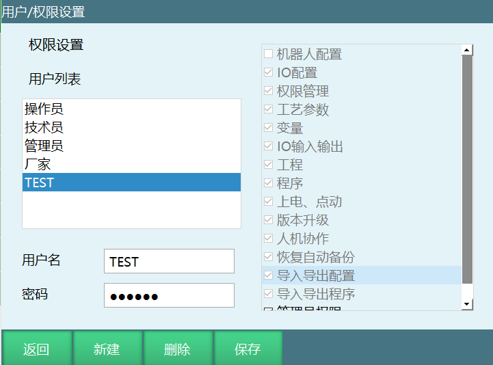 1. User-defined permission operations: 2. In Manufacturer/Manager permission, click [Permission Settings] to enter permission settings interface 3. Click [New] to define username, password, and permissions 4. Click [OK] 5. Click [Save] to complete user permission customization 1. User-defined permission operations: 2. In Manufacturer/Manager permission, click [Permission Settings] to enter permission settings interface 3. Click [New] to define username, password, and permissions 4. Click [OK] 5. Click [Save] to complete user permission customization |
 | Click [Settings] to open robot function settings interface 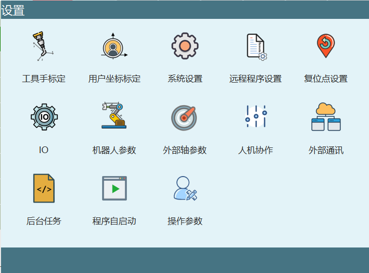 |
 | Click [Process] to open process selection interface Process types: Laser Cutting, Spraying, Polishing, Position-Search Tracking, Welding, Palletizing, Vision, Conveyor, Special Process, etc. 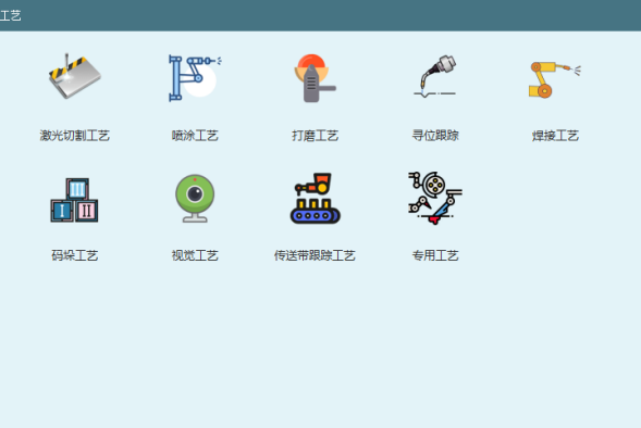 |
 | Click [Variable] to open the variable interface. View and set global position variable point information and global numeric variable assignments 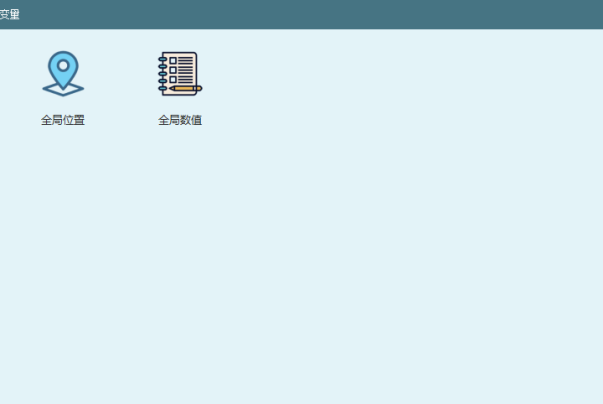 |
 | Click [Status] to open the status operation interface 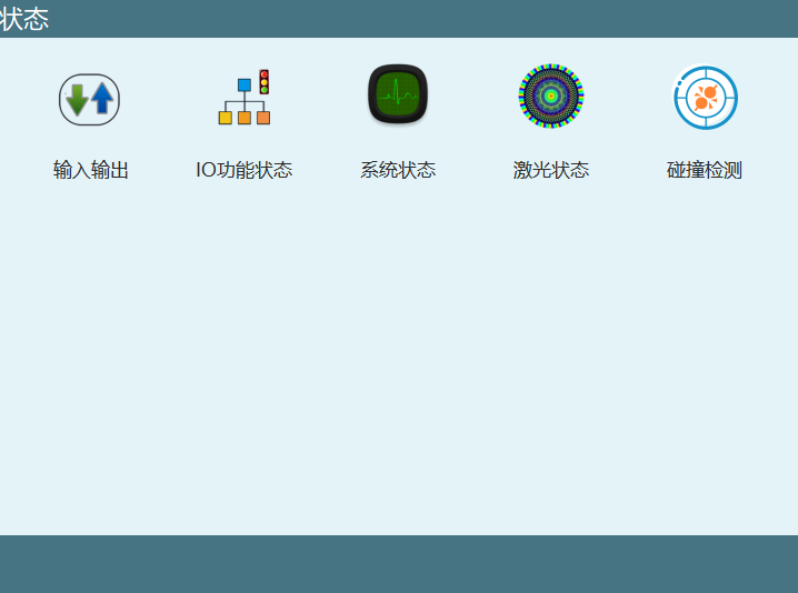 |
 | Click [Project] to open the project operation interface. Programs shown are project files created in the project interface 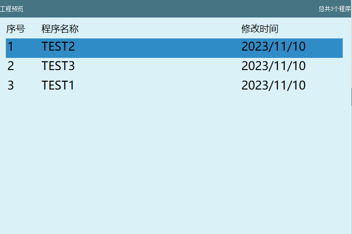 |
 | Click [Program] to enter the program interface 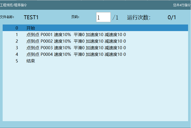 |
 | Click [Log] to open the log interface. View current errors, historical logs, log timestamps, log types (All, Message, Operation, Warning, Notification) 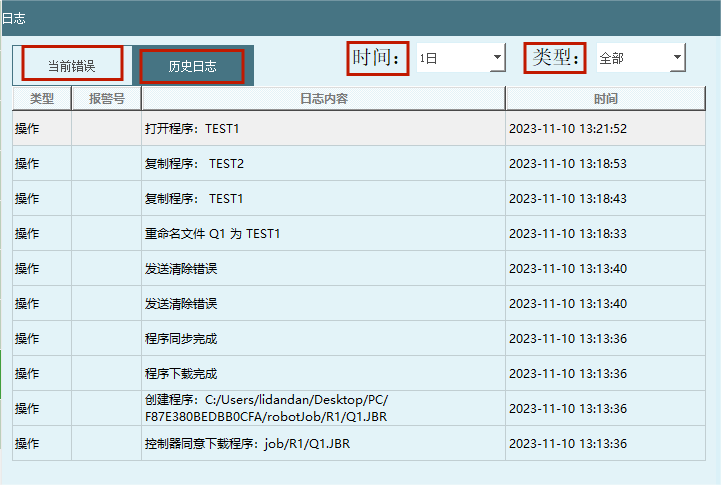 |
 | Click [Monitor] to open the monitor popup interface 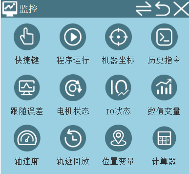 |
 | Date and time display |
Monitor Interface Parameter Description
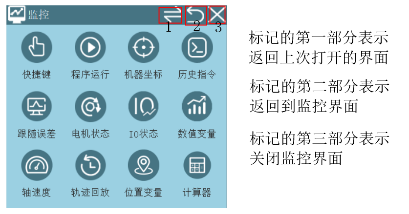
Shortcut Keys
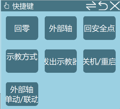
- [Return to Zero] Press power enable, click return to zero and the robot moves to zero position.
Zero position description: Every coordinate system has a point where all axes are 0, called the coordinate system origin. For the joint coordinate system, this point is called the zero position (all axes 1-6 of the robot have joint coordinates of 0).
[External Axis] Used to switch between the current robot and external axis.
[Return to Safety Point] Press power enable, click return to safety point and the robot moves to the set safety point.
The point in Settings - Reset Point Settings interface is the set safety point.
- [Teach Method Jog (Single)] Can switch between robot jog mode and drag mode.
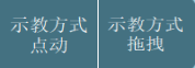
Drag description: After successful identification, select the drag method to switch to drag mode.
[Unplug Teach Pendant] After unplugging, the controller and teach pendant connection is disconnected.
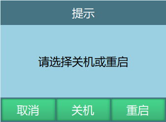
[Shutdown/Restart] Click to show the following prompt. Users can select Shutdown, Restart, or Cancel. Shutdown closes the controller and teach pendant. Restart restarts both. Cancel closes the prompt.
- External Axis Single/Linkage: In the monitor, you can switch external axis single/linkage mode. Prerequisite: the external axis for linkage must be calibrated.
Linkage: When jogging the external axis, the robot can follow with relative movement. When jogging the robot, the external axis does not move.
Single: When jogging the robot, the external axis stays still. When jogging the external axis, the robot stays still.
Program Execution
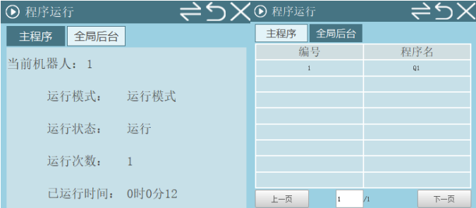
Main Program: During program execution, view the run mode (Teach, Run, Remote), run status (Paused, Stopped, Running), run count, and run time.
Global Background: Monitor the running global background job file during global background program execution.
Machine Coordinates
Monitor the robot's joint coordinates, Cartesian coordinates, tool coordinates, and user coordinates during motion.
Detection Distance: Detect the distance the robot moves from one point to another.
Historical Instructions
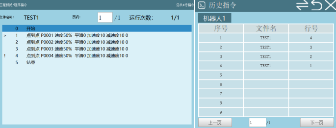
Sequence: The order when the program executes the current line instruction. Sorted by time in descending order (earliest at bottom, latest at top).
File Name: The currently running job file name.
Line Number: The line number of the current instruction in the job file.
Following Error (Unit: 1/10000)
Following error: The difference between the position command and actual position during motor movement, i.e., the difference between target position and actual position.
View the error values during robot operation on this interface.
Motor Status
Each joint axis has a motor. During robot motion, view each axis's motor torque, motor speed, motor load, encoder position, and motor current parameters.
Motor Torque: The rotational force output by the motor, describing the torque magnitude or strength.
Motor Speed: RPM (rotations per minute), indicating how fast the motor rotates.
Motor Load: The force or torque the motor bears during operation.
Encoder Position: The actual position records the current encoder value. The target position records the target encoder value.
Motor Current: View motor current parameters. Add motor current parameter units in operation parameters. Units: A or ‰.
IO Status
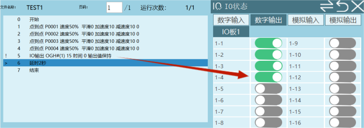
When signal parameters are set during job file execution, monitor digital and analog signals on this interface.
As shown:
Numeric Variables
When executing arithmetic instructions, the robot stores calculation results in target variables. View calculation results in Monitor - Numeric Variables:
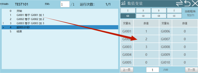
Note: Storing calculation results in local numeric variables will clear them to 0 after the entire job file completes!
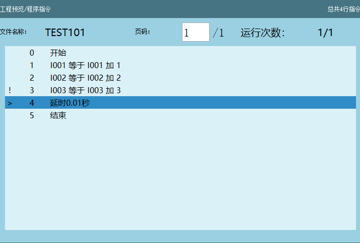
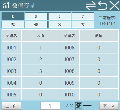
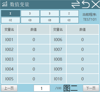
Example: Figure 1 shows the job file (TEST101) instructions still running, variable values remain as calculated. When all instructions in job file (TEST101) complete, local variable values are cleared, as shown in Figure 2.
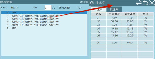
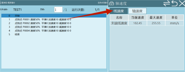
Axis Speed
During robot movement, based on the set instruction speed and global speed parameters, monitor current speed and maximum speed in Monitor - Axis Speed:
Trajectory Playback
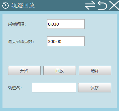
After successful identification, the robot can be dragged.
Sampling Interval: The interval between each point. For example, if set to 0.03 seconds, the interval between the first and second point is 0.03;
Maximum Sampling Points: Divide a drag trajectory into the set number of points. For example, 300 points divides the entire trajectory into 300 points;
Start: Power on, click Start, then drag the robot;
Stop: After dragging, click Stop. The drag trajectory is recorded;
Playback: Playback the recorded drag trajectory;
Clear: Clear the recorded drag trajectory;
Trajectory Name: The drag trajectory name. After dragging, the trajectory is recorded. Set the recorded trajectory name here. Later, select the recorded trajectory name in Settings - Human-Robot Collaboration - Hand-Guiding interface and click Playback;
Save: Save the drag trajectory. Saved trajectories are recorded in Settings - Human-Robot Collaboration - Hand-Guiding interface.
Position Variables
During robot operation, read target point information (coordinates, configuration, tool number, user number, posture values) and current program name:
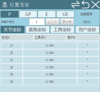
Note: Local position variables.
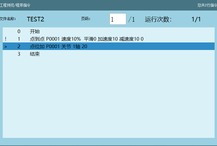
Program description:
Assume P0001 joint coordinates (10, 20, 30, -10, -20, -30). Monitor - Position Variables shows P0001 joint coordinates as (10, 20, 30, -10, -20, -30);
When the program runs to line 2, P0001 in Monitor - Position Variables - Joint shows: (30, 20, 30, -10, -20, -30);
After job file (TEST2) completes, P0001 in Monitor - Position Variables - Joint shows: (0, 0, 0, 0, 0, 0);
Re-running the program powers on P0001 (10, 20, 30, -10, -20, -30).
Note: The P0001 point in instruction 1 is the initial point of the target position. The value added in instruction 2 is an additional value. Values modified through addition, subtraction, etc. can be understood as additional values.
For example: P0001 joint J1 axis add 20 (this 20 is the additional value). The monitor displays initial value | additional value. In [Program] - [Variable] interface, the target variable point always shows the initial point. After all instructions in the job file complete, P0001 coordinates return to the initial coordinates.
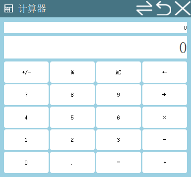
Calculator
Perform addition, subtraction, multiplication, and division operations.
Status Bar Introduction
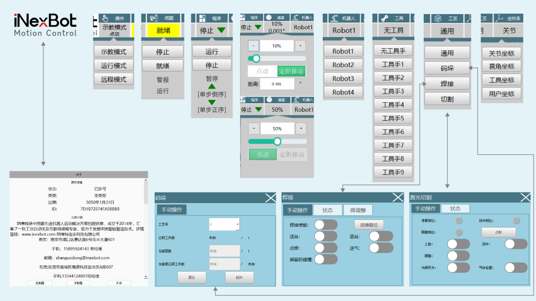
- Operation Mode
Teach pendant knob switches mode (Teach Mode, Run Mode, Remote Mode)
- Servo Status
- Stop, Ready:
Click the servo function key on the left to switch servo between Stop or Ready state.
- Running:
In teach mode, press the "Enable" button, servo status switches to "Running".
In run mode, press the "Start" button, servo status switches to "Running".
In remote mode, switch servo status through MODBUS address code or remote signal.
- Alarm:
Press the "Emergency Stop" button on the control cabinet/teach pendant, servo status switches to "Alarm".
Note: When emergency stop is connected to the servo, pressing the "Emergency Stop" button switches servo status to "Alarm".
- Program Status
- Running
In teach mode, press "Enable", click "Single Step" button, program status switches to running.
In run mode, press "Start" button, program starts running, program status switches to "Running".
In remote mode, through MODBUS address code or remote start signal, program starts running, program status switches to "Running".
Stop
Paused
In run mode, after program starts running, press "Stop" button, program status changes to "Paused".
In remote mode, through MODBUS address code or remote signal.
- Speed Status
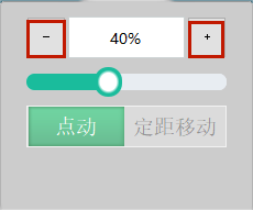
- Jog
Speed range: [1%, 100%]
Press [V+], [V-] at the bottom of the teach pendant to increase or decrease speed by 5% each time.
Click [+], [-] as shown below to increase or decrease speed by 1% each time.
- Fixed Distance Movement: After setting speed and distance, jog the robot. The robot will run the set angle or distance and stop.
Note: If stopped during jogging, re-jogging will run the set distance again, not the remaining distance.
Default values for fixed distance movement: Joint coordinates 0.1°, Cartesian coordinates 0.1mm.
When switching from jog to fixed distance movement, speed changes to default 10%.
For example: Jog speed is 50%, switching to fixed distance movement changes speed to 10%.
Jog/Fixed Distance Movement can only be switched in teach mode. Other modes show grayed out.
- Robot Status
- Robot: Robot 1, Robot 2, Robot 3, Robot 4
This system supports up to four robots.
Switch current robot by pressing the [Robot] button on the left of the teach pendant.
- External Axis: O1, O2, O3, O4, O5
This system supports up to five external axes.
Press the [External Axis] button on the left of the teach pendant to switch to external axis.
- Tool Status
Switch tools by pressing the [Tool] button at the bottom of the teach pendant.
Q&A for Retrieval
Q: What is the function of the [Servo] button on the teach pendant?
A: Click [Servo] to switch servo status (Stop, Ready).
Q: When can the [External Axis] button be used?
A: Only when an external axis is connected is the [External Axis] button available, used to switch between external axis and robot.
Q: What is the robot's drag mode? How to enter?
A: Drag mode allows directly dragging the robot to target points after enabling. Click [⭕] to enter drag mode. However, dragging is only possible after successful robot identification, selecting the appropriate drag method, and the slaveType file supporting it.
Q: What is the function of the [F/B] button?
A: Click [F/B] to select forward or reverse execution during single-step program execution. Forward runs instructions top to bottom, reverse runs bottom to top.
Q: How to adjust the robot's running speed?
A: Click [V-] to decrease global speed by 5% per click; click [V+] to increase global speed by 5% per click. Or drag the speed slider at the top of the teach pendant.
Q: What is the function of the [Tool] button?
A: Click [Tool] to switch tools.
Q: How to switch between different coordinate systems?
A: Click [Coordinate] to cycle through joint, Cartesian, tool, and user coordinates.
Q: What does the operation mode knob on the teach pendant do?
A: Knob left = Teach mode, center = Run mode, right = Remote mode.
Q: How to start and stop programs?
A: In run mode, click [Start] to begin program execution. Click [Stop] to pause the running program.
Q: What are the [-] and [+] buttons for?
A: [-] jogs the corresponding axis in the negative direction. [+] jogs in the positive direction.
Q: How to set user permissions?
A: In the user interface, modify Operator, Technician, Manager, Manufacturer user login. In Manufacturer/Manager permission, click [Permission Settings], click [New], define username, password, permissions, click [OK] and [Save].
Q: What is the function of the [Monitor] button?
A: Click [Monitor] to open the monitor popup, viewing robot status, signal monitoring, numeric variables, axis speed, and other information.
Related Resources
- Teach Pendant Image Replacement
- Teach Pendant Theme Color Modification Tutorial
- Human-Robot Collaboration
- External Axis User Manual
- System Function Debugging Manual
Version History
| Version | Date | Changes | Author |
|---|---|---|---|
| 1.0.0 | 2026-04-07 | Initial version | MUZI165 |