System Function Debugging Manual
System Settings
Version Upgrade
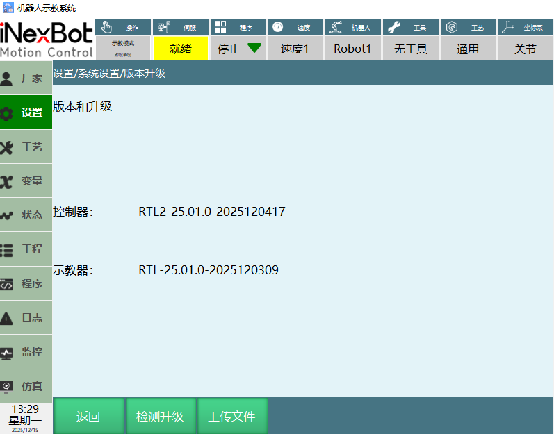
T30 Upgrade
Controller and teach pendant currently use the program version.
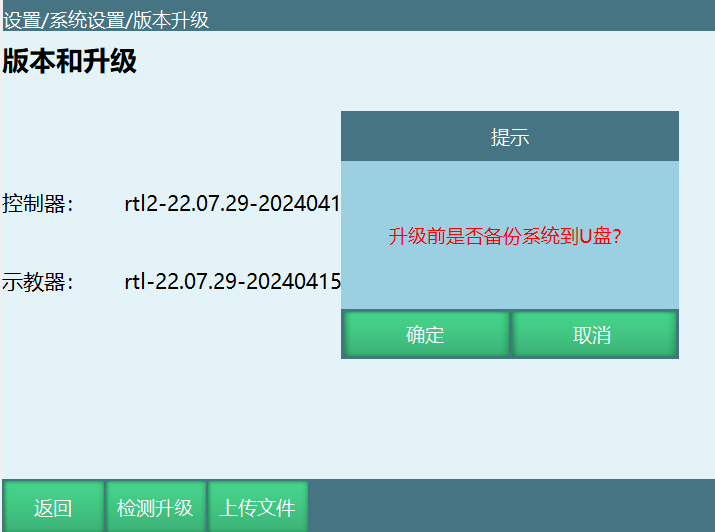
Check Upgrade: Insert USB drive into teach pendant USB port, place the program package to upgrade in the USB root directory, click "Check Upgrade". As shown below, a prompt will appear asking whether to backup the system. Click "Cancel" to enter the upgrade package page.
As shown below, select the program and click [OK] on the upgrade file interface. After clicking OK, a second confirmation interface appears. Click [OK] again to start upgrading the program.
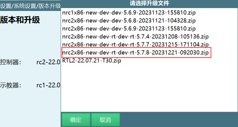
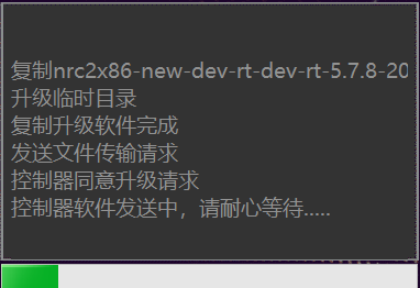
Files that can be upgraded through check upgrade include controller program, teach pendant program, language packs, etc.
System Backup: Insert USB drive into teach pendant USB port, place the program package to upgrade in the USB root directory, click "Check Upgrade". As shown below, a prompt will appear. Click "OK" to backup system to USB.
PC Version Upgrade
- Teach pendant program upgrade: Place the corresponding PC version program in the PC folder's root path.
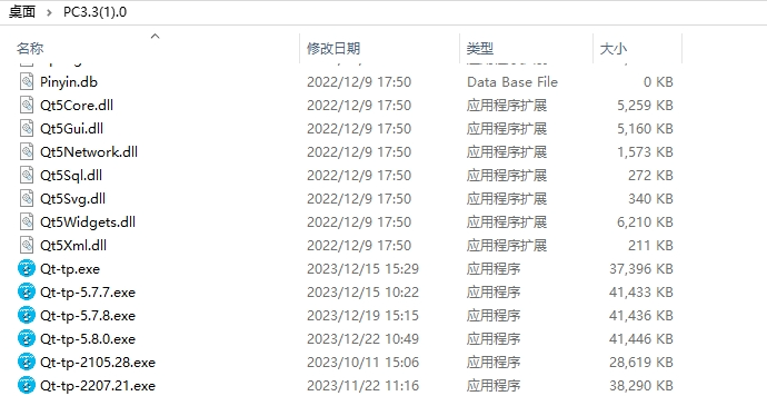
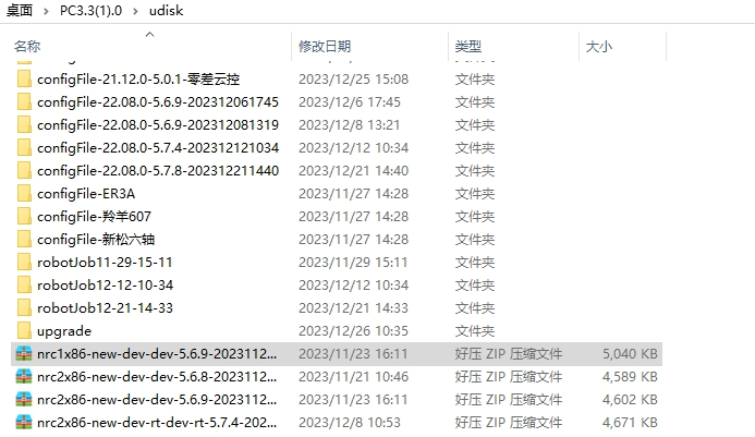
- Controller program upgrade: Create a new "udisk" folder under the PC folder, then place the controller program in the udisk folder.
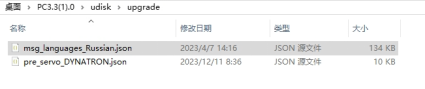
- Upload files: Create a new "upgrade" folder under the udisk folder. Upload file path PC-udisk-upgrade.
IP Settings
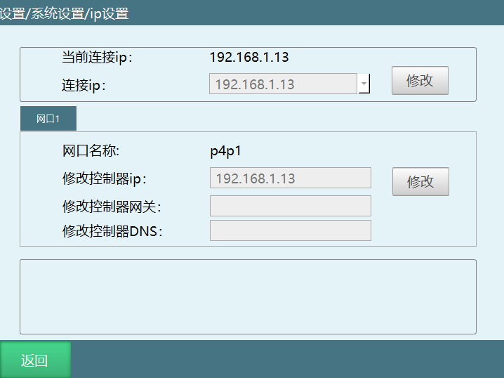
Steps to modify IP:
- Record the new IP address before modifying.
- Click the [Modify] button corresponding to "Modify Controller IP", "Connection IP", "Modify Teach Pendant IP".
- Enter new IP address in the input box, click [Save]. Teach pendant IP takes effect after system restart. Connection IP and controller IP take effect immediately after clicking [Save].
Note:
- Do not modify IP unless necessary to avoid usage issues.
- If modifying controller IP to non-default value (192.168.1.13), please record the controller IP yourself.
Scan IP Function
Function: Controller can scan controller IPs in the same LAN (connected to the same switch/hub/router) and same network segment.
Note: This function has a delay on first scan.
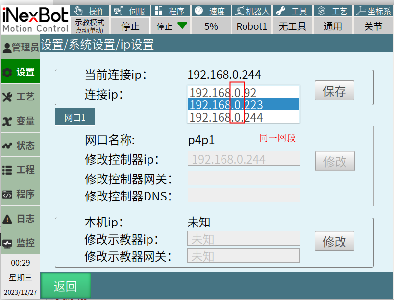
- IP settings interface scan IP function.
Click [Modify] on connection IP row, then click the dropdown that appears and wait 3-4 seconds to scan other controller IPs in the same network segment and LAN. Wait for search to complete, displayed sorted by IP last digit. Select the searched IP to update to the text box. Original input function remains unchanged. As shown:
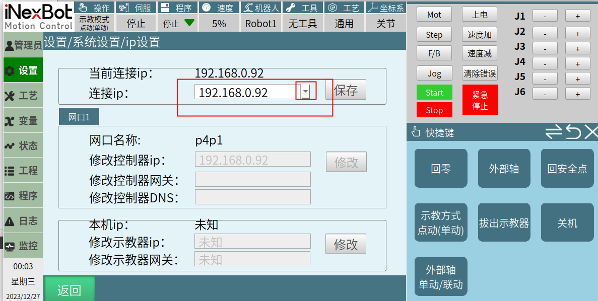
- Monitor - Shortcut Keys interface remove teach pendant and insert teach pendant, scan IP function.
- Original text box input function remains unchanged, can enter IP address to connect.
- Can click dropdown popup to search 6002 port addresses under teach pendant network segment. Wait for search to complete, displayed sorted by IP last three digits. Select searched IP to update to text box. Click confirm to start connecting.
Specific interface as shown:
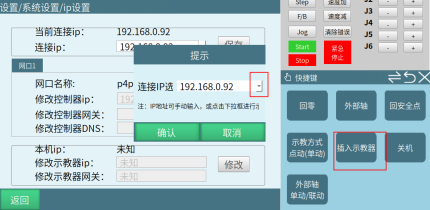
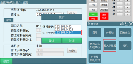
One-Key Backup System:
Insert USB drive into teach pendant USB port, click Settings - System Settings - One-Key Backup System. SystemBackup filename prefix is T30-1 or T30-2 based on which system program was running during backup. nrc corresponds to T30-1-SystemBackup, nrc2 corresponds to T30-2-SystemBackup.
- Backup file naming format: T30-1-SystemBackup/T30-2-SystemBackup + specific date.
As shown:
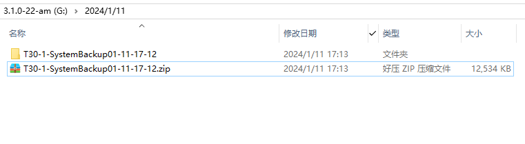
Backup path: USB root directory.
Backed up files:
Teach pendant backup files: config.db, Pinyin.db, ServoError.db, TColor.db, Userdata.db, T30_ARM_Linux_Teach-pendant (teach pendant program).
Controller backup files: Controller config file config, craft files, dragPos trajectory files, eni files, job files, lua files, multilingual msg_languages files, preset parameters, variant variables, controller program C1102_X86_Linux-RT_Robot-controller.
Program backup description:
Version 2403 and above modified the controller and teach pendant startup program names for different platforms. Therefore backup program names differ by platform. See table below.
| Platform | Original Program | Current Program |
|---|---|---|
| C1102 | Actions: nrc.out | C1102_X86_Linux-RT1_Robot-controller |
| Igh: nrc2.out | C1102_X86_Linux-RT_Robot-controller | |
| C1200 | nrc2.out | C1200_X64_Linux-RT_Robot-controller |
| C1201 | nrc2.out | C1201_X64_Linux-RT_Robot-controller |
| C2200 | nrc.out | C2200_ARM_Linux-RT_Robot-controller |
| T01 | nrc.out | T01_ARM_Linux-Xenomai_Robot-controller |
| C2200-A01 | nrc.out | C2200-A01_ARM_Linux-RT_Robot-controller |
| T30 | Qt-tp | T30_ARM_Linux_Teach-pendant |
Upload files: Click this button to upload controller language files (e.g., Russian msg_languages_Russian.json), controller decryption file (offlinelicense.txt), initialization file (offlineInitialization.txt), servo parameter identification (pre_servo_DYNATRON.json).
Return: Click [Return] to exit version upgrade interface.
Export Log
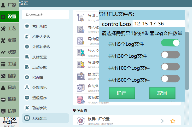
Steps:
- Insert USB drive into teach pendant USB port.
- Click [Settings] - [System Settings] - [Export Log].
- Select the number of Log files to export, click [OK] to start exporting.
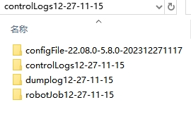
- Exported log format: controlLog-default is teach pendant date, supports renaming, as shown.

- Exported log includes controller config files, control logs, crash logs and job files.
Import Program

In system settings interface, import program steps:
- Insert into teach pendant USB port;
- Click [Settings] - [System Settings] - [Import Program], select the job file to upload;
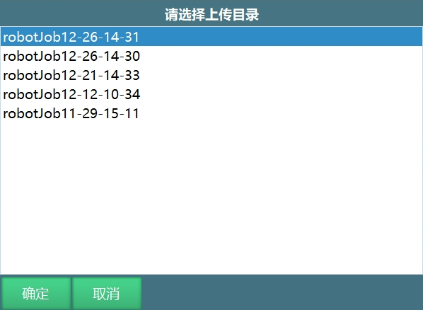
- Click [OK], select the job file to upload;
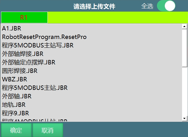
Turn on "Select All" to import all job files. Turn off Select All to import one job file or multiple at a time;
- Click [OK] to start importing. After successful import, the project interface displays the imported program name.
User-defined job file import:
- Create a folder named "robotJob" in the USB root path, and create a folder named "R1" inside it;
- Place programs with ".JBR" extension in the R1 folder;
- Insert USB drive into teach pendant USB port;
- Click [Settings] - [System Settings] - [Import Program];
- Select robotJob, click [OK];
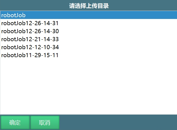
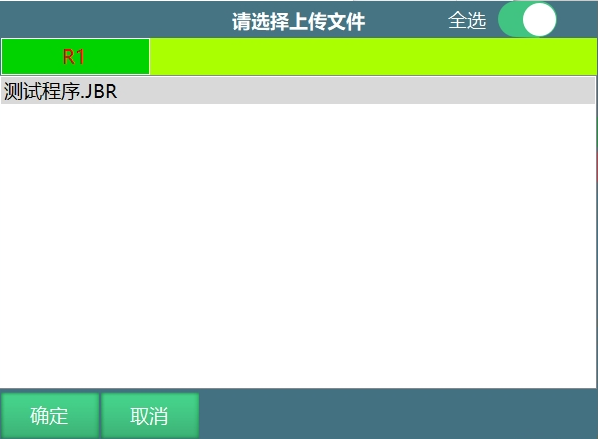
- Click [OK] to start importing. After successful import, the project interface displays the imported program name.
Export Program
In the system settings above, export program steps:
Insert USB drive into teach pendant USB port.
Click [Settings] - [System Settings] - [Export Program].
Program is exported to USB root directory.
Export program naming format: "robotJobxx-xx-xx-xx (default is current date/time, supports renaming)" directory.
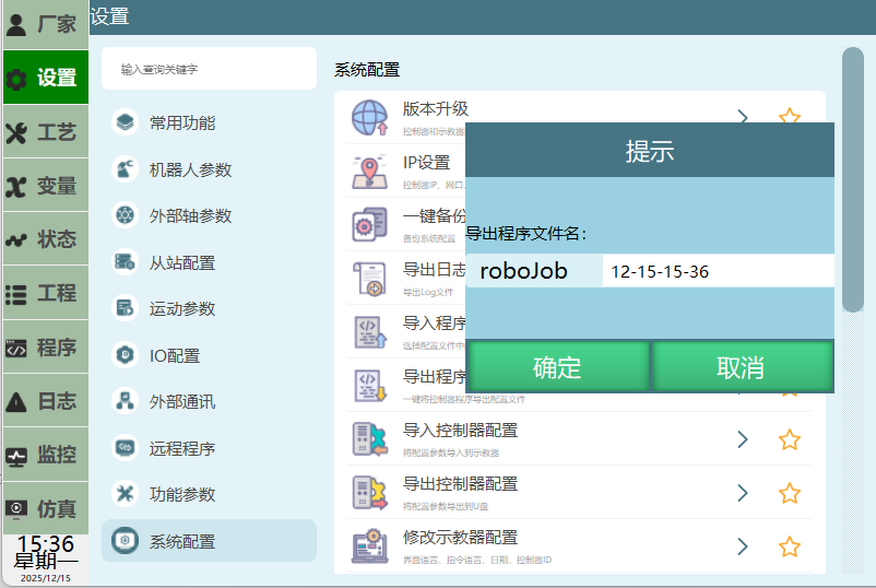
As shown:

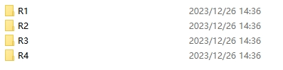
Export program can export all programs for robot1, robot2, robot3, robot4. R1 folder contains robot1 programs, R2 contains robot2 programs, R3 contains robot3 programs, R4 contains robot4 programs.
Import Controller Configuration
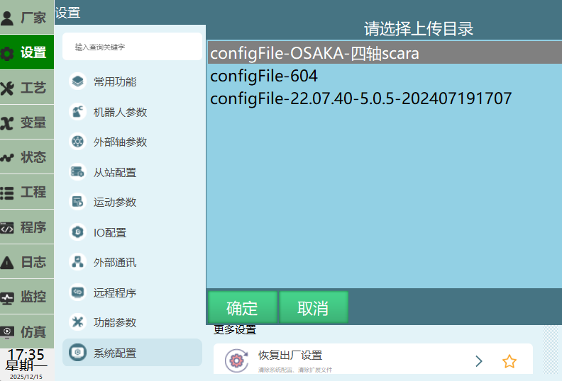
Steps:
Insert USB drive into teach pendant USB port.
Click [Settings] - [System Settings] - [Import Controller Configuration].
Select the configuration file to import, click [OK] to enter configuration file selection interface. Turn on "Select All" to import all files. Turn off "Select All" to import one or multiple files.
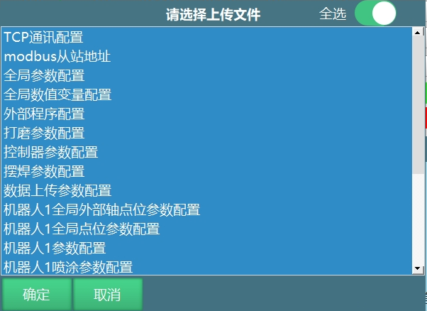
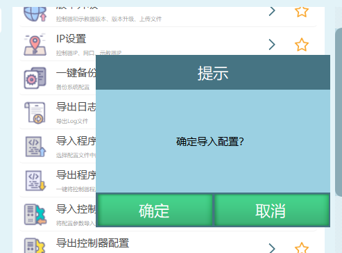
- As shown, click [OK] to start uploading configuration file. After successful import, restart controller.
Export Controller Configuration
Steps:
- Insert USB drive into teach pendant USB port.
- Click [Settings] - [System Settings] - [Export Controller Configuration].
- Click [OK] to start exporting configuration.
- Exported configuration file format: configFile default is current program major version-minor version-specific date, supports renaming, as shown.
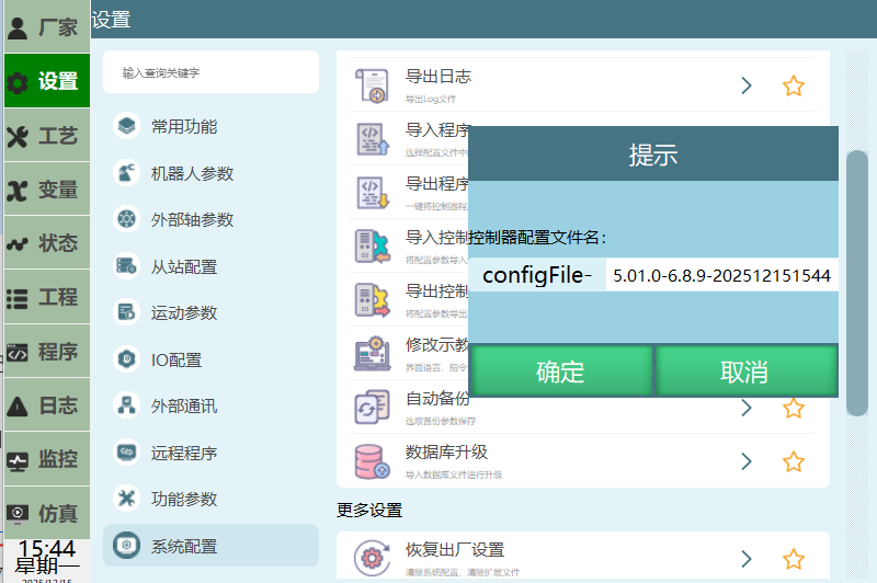
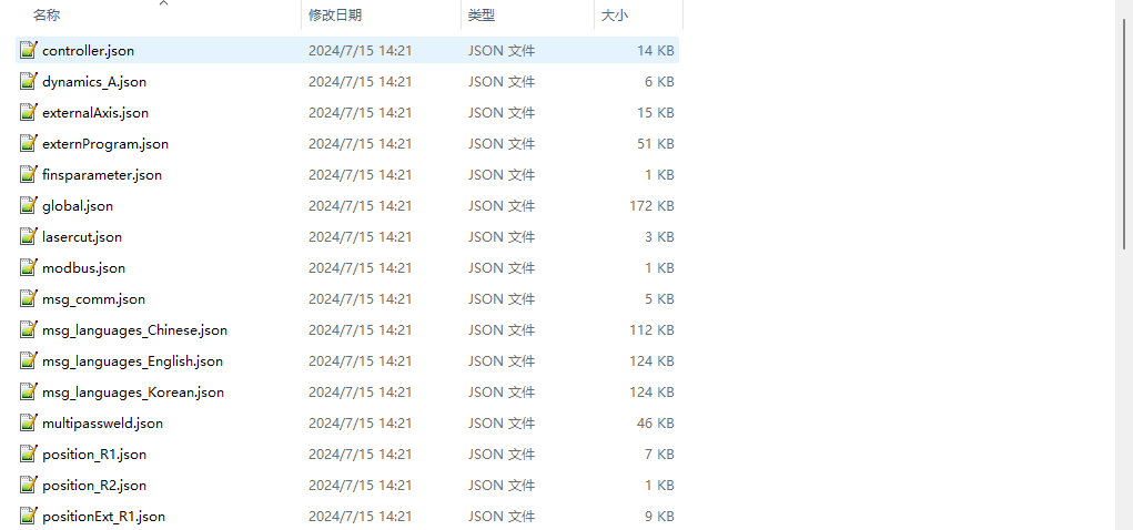
Exported configuration file includes parameters: Modbus config file modbus.json, Chinese language file msg_languages_Chinese.json, conveyor tracking parameter config conveytrack.json, global parameter config global.json, global string variable stringVariant.json, Robot 1 global position parameter config position_R1.json, Robot 1 parameter config Robot_A.json, etc.
Modify Teach Pendant Configuration
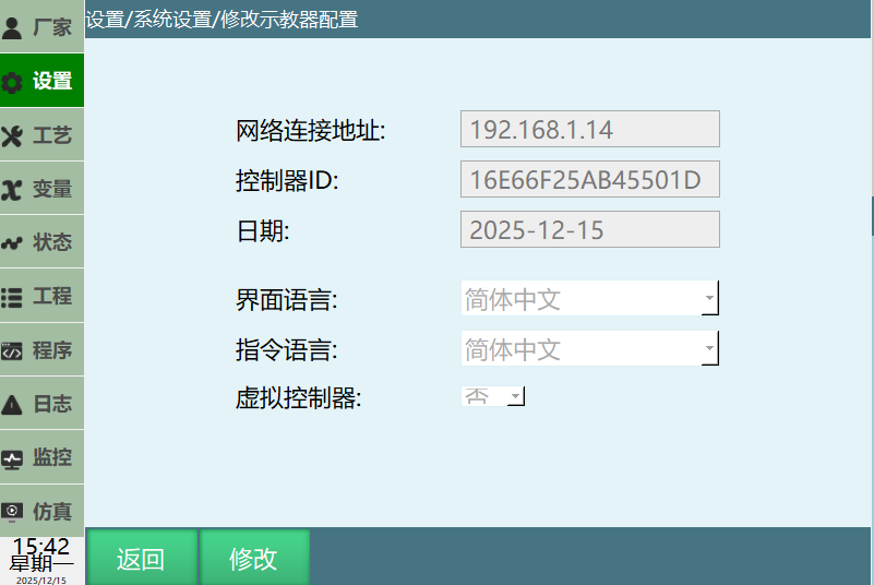
- Interface Language: Switch teach pendant interface language, e.g., switch to Russian, Korean, Thai, etc. For how to switch interface language, refer to the "Multilingual Function Manual".
- Instruction Language: Instruction language only has current interface language and English. For example, if current interface language is Korean, instruction language is Korean and English.
- Virtual Controller: Selecting Yes for virtual controller only allows viewing each interface, cannot modify or save parameters. Only supports PC connecting to virtual controller.
Auto Backup
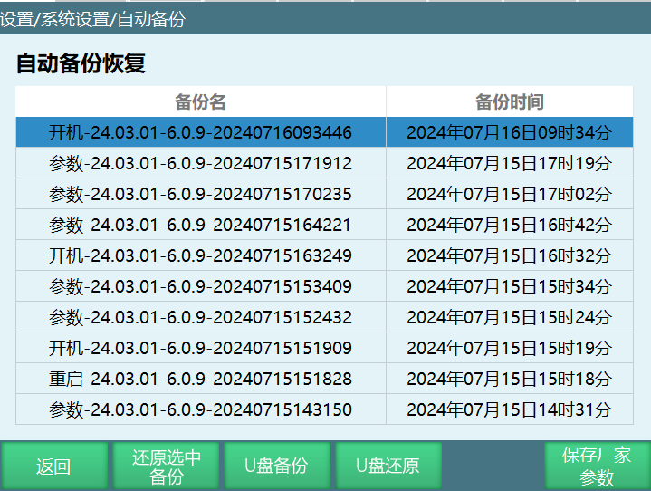
- Controller auto backup function:
- Backup content: Programs, parameters.
- Maximum backup count: 10.
- Backup naming: By premise, version, time. Example: Parameter modified at 6:36 on July 15, 2024, backup name "Parameter-22.08-5.8.0-20240715143150"
- Backup trigger premises: Startup, parameter modification, program modification, upgrade.
- Backup frequency:
- Backup once after confirming version and parameters are normal during startup;
- Backup once if no parameter modification within 5 minutes after parameter modification;
- Backup once if no modification within 5 minutes after program modification (insert instruction, modify instruction); Backup once before upgrade.
- Function description:
- Restore selected backup: Select the backup to restore. Cursor will appear after selection. Click "Restore Selected Backup" button.
Popup prompt, click OK.
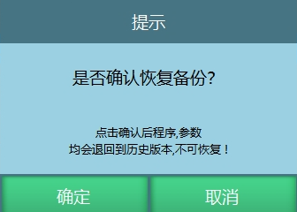
During restoration, do not power off.
USB Backup:
Steps: Insert USB drive into teach pendant USB port, click USB Backup. SystemBackup filename prefix is T30-1 or T30-2 based on which system program was running during backup. nrc corresponds to T30-1-SystemBackup, nrc2 corresponds to T30-2-SystemBackup.
Backup file naming format: T30-1-SystemBackup/T30-2-SystemBackup + specific date.
As shown:
Backup path: USB root directory.
Backed up files:
Teach pendant backup files: config.db; Pinyin.db; ServoError.db; TColor; Userdata.db; T30_ARM_Linux_Teach-pendant (teach pendant program)
Controller backup files: Controller config file config; craft files; eni files; job files; lua files; multilingual msg_languages files; preset parameters; variant variables; controller program C1102_X86_Linux-RT_Robot-controller.
Program backup description: Version 2403 and above modified startup program names for different platforms. Therefore backup names differ by platform. See table below:
| Platform | Original Program | Current Program |
|---|---|---|
| C1102 | Actions: nrc.out | C1102_X86_Linux-RT1_Robot-controller |
| Igh: nrc2.out | C1102_X86_Linux-RT_Robot-controller | |
| C1200 | nrc2.out | C1200_X64_Linux-RT_Robot-controller |
| C1201 | nrc2.out | C1201_X64_Linux-RT_Robot-controller |
| C2200-A01 | nrc.out | C2200-A01_ARM_Linux-RT_Robot-controller |
| T30 | Qt-tp | T30_ARM_Linux_Teach-pendant |
USB Restore:
First get the system's currently running program information, compare with backup system file's filename. nrc corresponds to T30-1, nrc2 corresponds to T30-2. When current running system matches backup system file name, system restore is allowed. Otherwise not allowed.
Insert USB drive into teach pendant USB port, click System Restore, select system restore file. After upload succeeds, restart teach pendant.
Save Manufacturer Parameters:
After saving manufacturer parameters, under admin permission, factory reset can restore factory robot parameters, IO and tool hand configuration. This button only displays under manufacturer permission.
Database Upgrade
- Used to upgrade config.db file. This file saves teach pendant configuration such as IP, some parameters in operation parameters, etc.
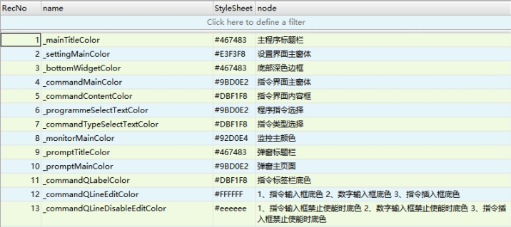
- Modify theme color: New TColor.db, database stores theme colors.
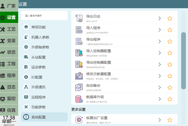
Operation steps:
- Click Settings - System Settings - Maintenance Mode, in parameter selection interface turn on "Use stylesheet from database" button.
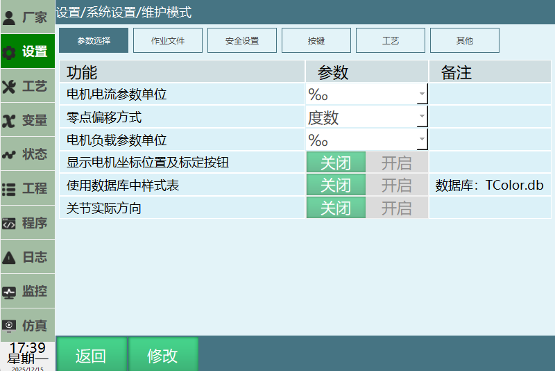
- Open TColor.db file with SQLite software, modify database stylesheet column color code, save.
- Place modified TColor.db file in USB root directory. Click Settings - System Settings - Database Upgrade, select TColor.db file and click [OK].
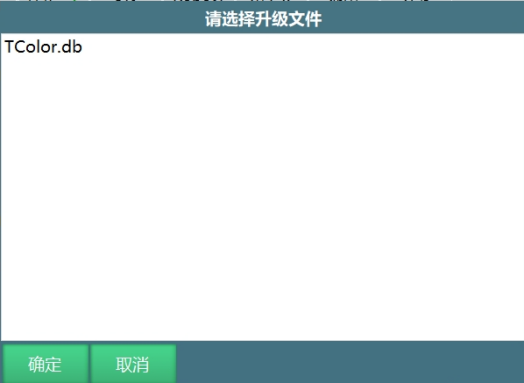
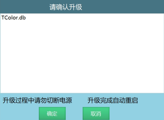
- Second confirmation popup, click OK. After database upgrade completes, restart teach pendant to take effect.
More Settings
Factory Reset
As shown below, users can select configuration files to clear based on their needs.
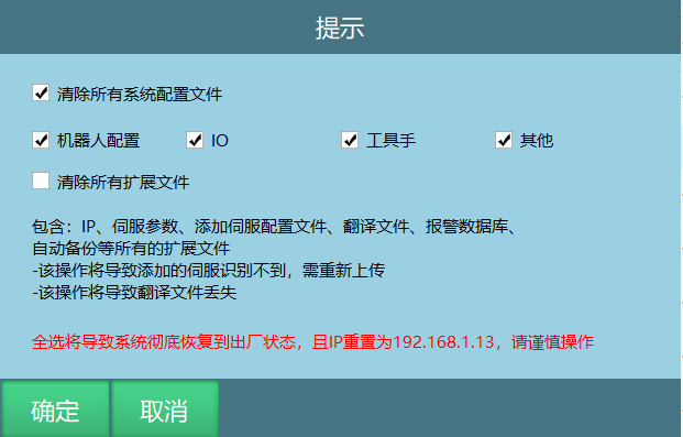
Factory reset requires caution! Please backup all parameters and program files before performing this operation!
Steps:
- Enter Settings - System Settings - More Settings interface;
- Click [Factory Reset] button. In the popup prompt, there are two choices: Clear system configuration files and all extension files. Select the configuration file type to clear;
- Click [OK] button, then click [OK] in the second confirmation box. Selected configuration files are restored to factory settings.
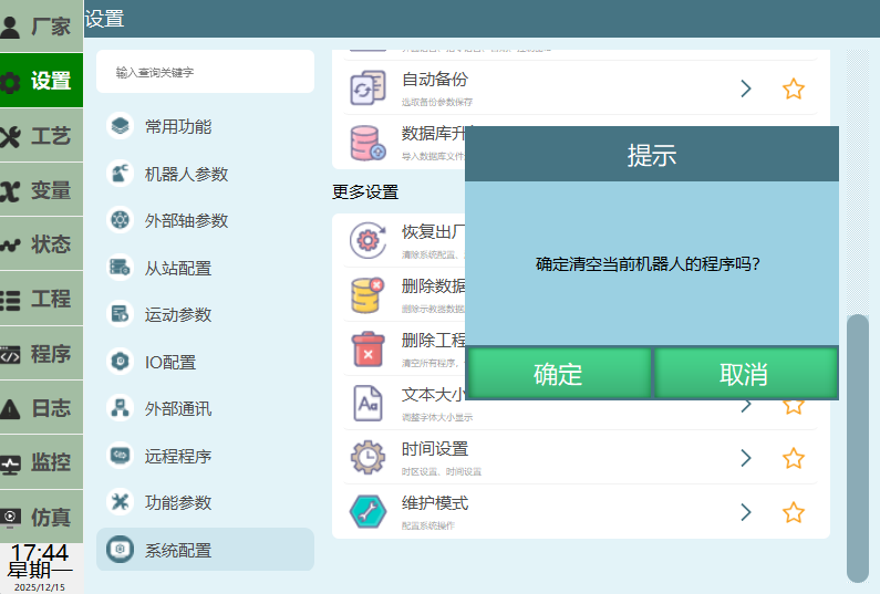
Delete Database
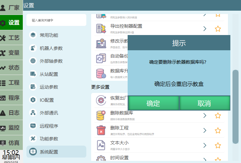
Select Delete Database, click [OK] to delete the config.db file in the teach pendant.
Delete Project
Select Delete Project, click [OK]. After programs are cleared successfully, created job files are cleared.
Caution: Programs cannot be recovered after being cleared!
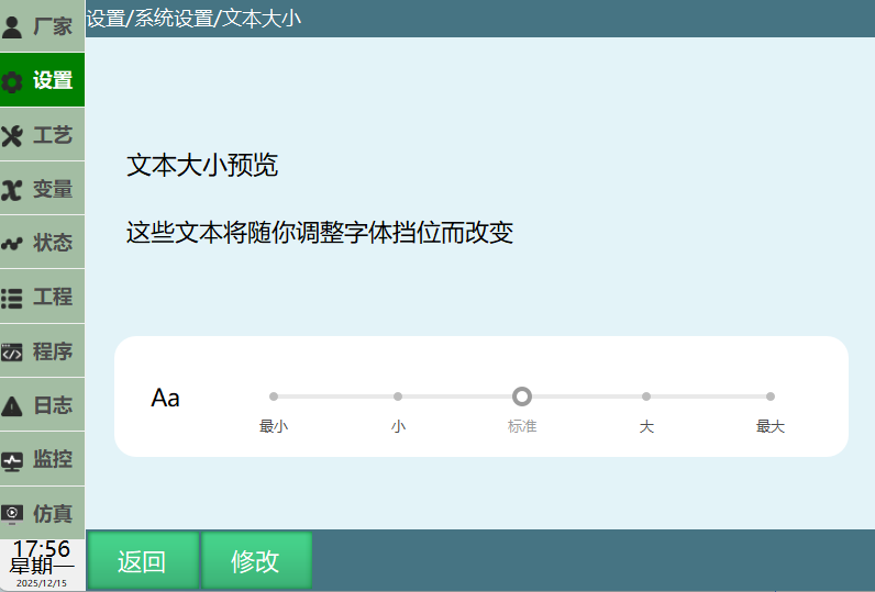
Text Size
Path: Settings - System Configuration - Text Size
Function: Adjust interface font size
Click - Modify - Select text size
Time Settings
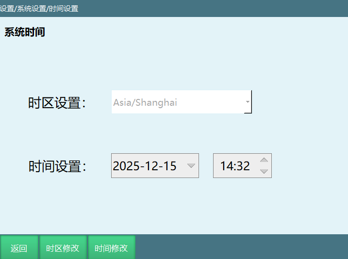
[Modify]: Click [Time Modify] button, set year, month, day, hour, minute.
[Modify]: Click [Timezone Modify] button, set timezone.
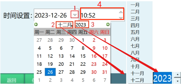
How to modify date:
- Click step 1 marked below, modify date popup appears.
- Click step 2, modify month.
- Click step 3, modify year.
Modify time:
- Click step 4 marked below, modify time.
[Return] Click return button to exit this interface.
[Save] Click save button, time setting successful.
Maintenance Mode
Path: Settings - System Settings - Maintenance Mode
Parameter Selection
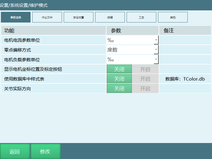
- Motor current parameter unit: permille, A Description: Modify unit display in Monitor - Motor Status - Motor Current interface
- Zero point offset method: Degrees, Encoder Value Description: Modify unit in Robot Parameters - Zero Position - Zero Point Offset interface. Select degrees to display °, select encoder value to display inc
- Motor load parameter display unit: permille, mNm Description: Modify unit display in Monitor - Motor Status - Motor Load interface
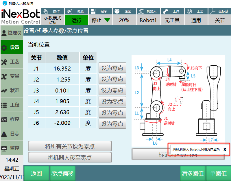
- Display motor coordinate position and calibration button: Turn on switch to add motor position coordinate in Monitor - Machine Coordinates interface, and add [Mark No-Clearance Direction] button in Settings - Robot Parameters - Zero Position interface
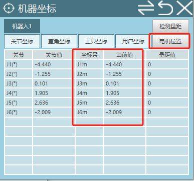
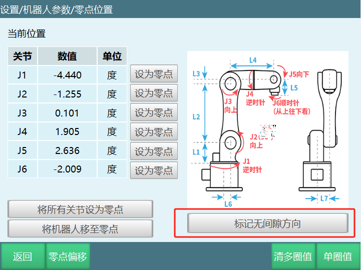
Example description: Take robot axis 1 as example. In Settings - Robot Parameters - Joint Parameters - Other Parameters interface, set a value for [Gear Backlash]. When gear backlash has a value, an error appears because calibration hasn't been performed. At this time, go to zero position interface to mark no-clearance direction.
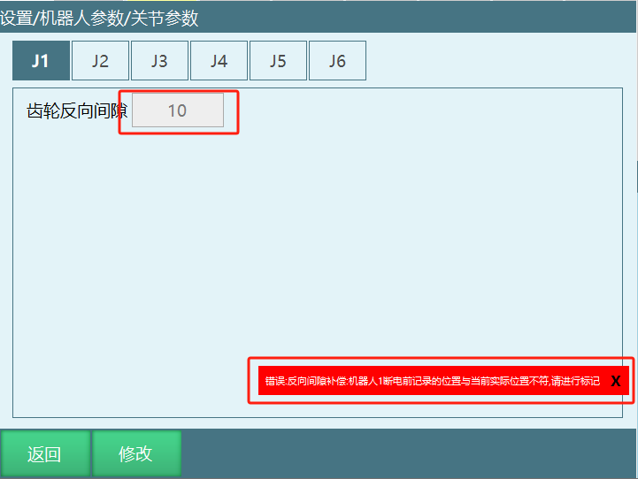
Calibration method as follows:
- Jog J1+. Since gear backlash value is 10, motor position must be greater than 10 during axis 1 movement.
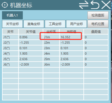
- When greater than 10, click [Mark No-Clearance Direction Button]. A success message will appear.
Verify effectiveness:
- After marking successfully, check if monitor robot coordinate and motor position coordinate's axis 1 are the same.
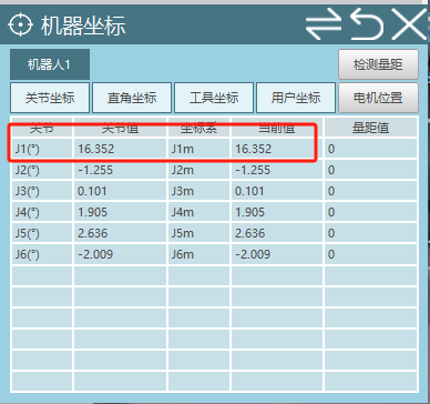
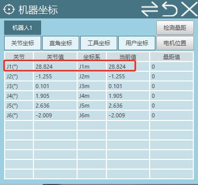
- Power on and jog robot axis 1. When jogging positive direction, robot coordinate and motor position coordinate are consistent. When jogging negative direction, robot coordinate and motor position coordinate differ by 10, which is the gear backlash value.
- Use stylesheet from database: Turning on "Use stylesheet from database" switch allows modifying theme color. If switch is not turned on, upgrading database file will not take effect.
Steps to modify theme color:
- Open TColor.db file with SQLite software, modify database stylesheet column color code and save, as shown:
- Place modified TColor.db file in USB root directory. Click Settings - System Configuration - Database Upgrade, select TColor.db file and click [OK].
- Second confirmation popup, click [OK]. After database upgrade completes, restart teach pendant for modified theme color to take effect.
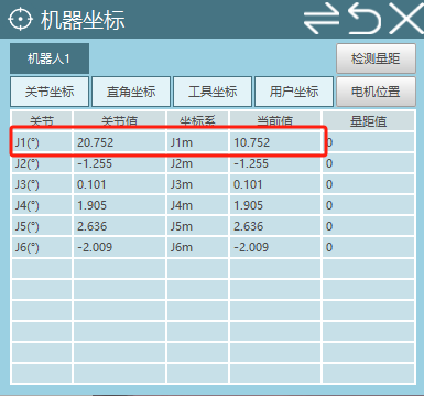
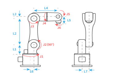
- Joint actual direction: Joint actual direction is set relative to model direction. Same as model direction select 1, opposite select -1. Set based on actual requirements. (If you want robot axis motion direction opposite to model, adjust as follows)
- Initial state, jog each axis +, adjust model direction to ensure robot motion direction matches model;
- Switch to Cartesian coordinate system, verify XYZ direction is normal (for 6-axis example: facing robot, X+ forward, Y+ right, Z+ up);
- To use joint actual direction function, go to [Settings] - [Maintenance Mode] interface, turn on button after joint actual direction;
- Joint actual direction is in [Settings] - [Robot Parameters] - [Joint Parameters] - [Other Parameters] interface;
- If you want axis 2 + motion opposite to model, change joint actual direction to -1;
- Jog the axis to verify change is complete, switch to Cartesian coordinate system to verify direction is normal.
Job File
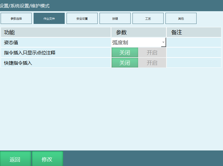
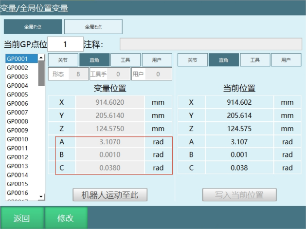
- Attitude value: Degrees, Radians Description: After modifying attitude value, position variable attitude axis (ABC axes) parameters and units will change accordingly.
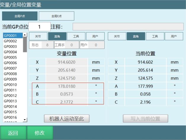
Instruction insert only shows point comment Description: After turning on, inserted points only show user-defined comments, not specific instruction names. After turning off, specific instruction names display normally.
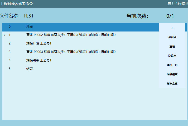
Shortcut instruction insert Description: After turning on, shortcut instruction icon appears in program instruction interface. Default has preset shortcut instructions. Users can remove default shortcut instructions and add desired ones. Click + to show shortcut instructions. As shown, directly click point-to-point or other instructions to quickly insert target instructions.
Add frequently used: Click instruction overview to enter instruction insertion interface, select target instruction and click Add Frequently Used to select.
Remove frequently used: Click instruction overview to enter instruction insertion interface, select instruction to remove and click Remove Frequently Used to remove.
Safety Settings
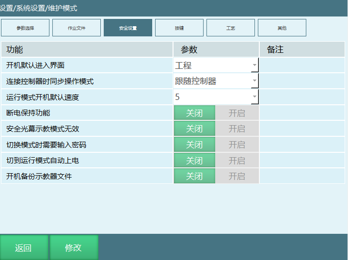
- Startup default interface: User permission interface, Project interface
- Sync operation mode when connecting to controller: Follow controller, Follow mode knob Follow controller: When controller and teach pendant are connected normally, teach pendant follows the mode sent by controller. Follow mode knob: When controller and teach pendant are connected normally, switch operation mode through knob.
- Run mode default startup speed: [1,100] Description: After modifying speed, restart system according to teach pendant interface prompt. After restart, switch to run mode. Run mode speed is the modified speed.
- Power-off retention function Main function: In case of sudden power failure or external power disconnection, controller immediately saves current robot position, program status, variable values, etc. after external power disconnects. After controller external power reconnects, can recover to pre-power-off state. (Requires hardware-supported UPS controller or controller external hardware UPS for this function to take effect)
Power-off retention function message: After external power reconnects, if function is effective, startup will prompt "Power-off retention has taken effect"
Data recovered after power-off retention is triggered:
- Robot position, external axis position (virtual servo will not recover);
- I, D, B, S, GI, GD, GB, GS numeric variables;
- IO forced input/output;
- Program run position current line, last run line, breakpoint run, program instruction prior assignments, IO status;
- Global background, local background tasks;
- Modbus values, variables.
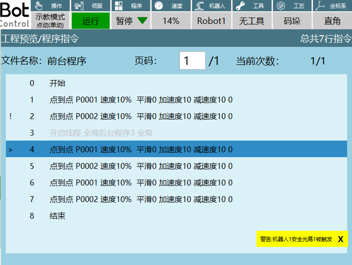
- Safety curtain teach mode invalid: Turn on switch, safety curtain signal is invalid, does not affect program execution. Turn on switch, triggering safety curtain in teach mode, program continues normally.
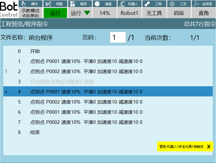
Turn off switch, triggering safety curtain in teach mode, program pauses.
- Password required when switching modes: Turn on switch, users need to enter password when switching operation mode. Default is off.
- Auto power on when switching to run mode: Turn on switch to auto power on when switching to run mode.
- Backup teach pendant files on startup: Teach pendant backs up twice on each startup. If not turned on, only data sync, no backup.
Buttons
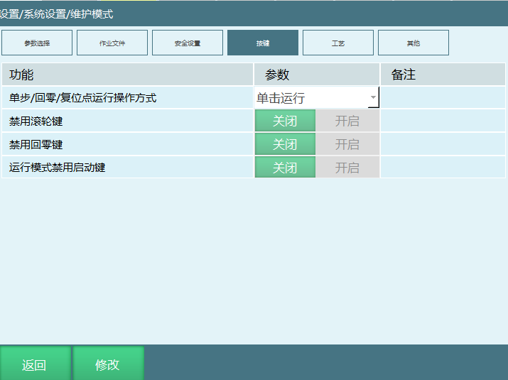
Single Step/Return Zero/Reset run operation method: Click to run, Hold to run Click to run: Press the corresponding button once, robot executes the corresponding function. Hold to run: Need to continuously hold the corresponding button, robot executes the function.
Disable scroll wheel: Turn on to disable teach pendant right scroll wheel. Disabled state scroll wheel is invalid. Turn off switch to restore scroll wheel.
Disable return zero key: Turn on switch to disable return zero key. Clicking teach pendant zero point button and monitor - shortcut keys return zero will show prompt [Robot return zero key has been disabled]. Turn off switch to restore return zero function.
Run mode disable start key: Turn on disable switch. In run mode, clicking teach pendant [Start] key is invalid, cannot start program. Turn off disable switch, click [Start] in run mode to start program.
Craft
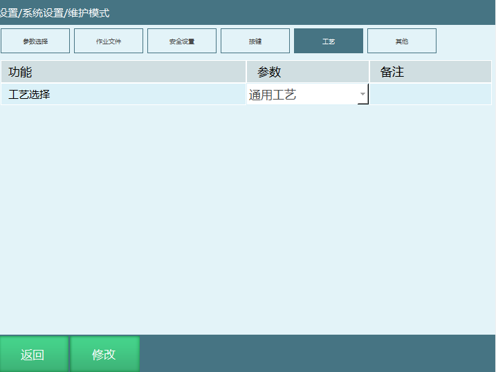
- Craft selection: General, Special, Palletizing, Welding and Cutting Description: When selecting General, teach pendant top craft status bar displays General, Palletizing, Welding and Cutting. If only selecting a single craft, teach pendant top craft status bar only displays the selected craft type.
Other
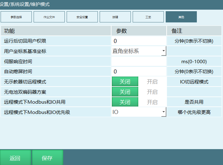
- Return to user permission after run (unit: minutes): Set time parameter. After program runs to set time, user permission switches to operator.
- User coordinate system reference coordinates: Version 2501 not yet implemented.
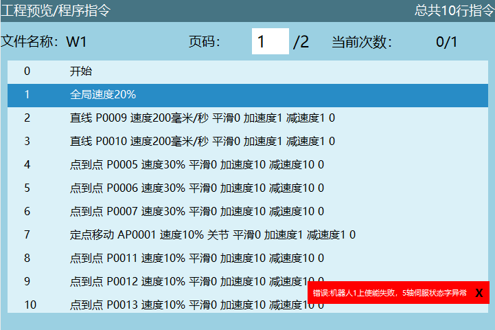
- Servo response time: Prevents multiple control devices sending signals to servo causing servo state confusion. If response time exceeded without servo reply, servo enable/disable is considered failed, as shown.
- Auto screen off time unit (minutes): After reaching set time, teach pendant screen turns off. Fill 0 to never turn off screen.
- No teach pendant switch to remote (IO switch to remote): No need to switch mode through teach pendant knob. When teach pendant is not connected, triggering remote IO signal automatically switches to remote mode.
Description: In Settings - Remote Program - Remote Program Settings interface, remote parameters are already configured (start signal, stop and program reservation signals). Assume removing teach pendant, directly give start signal, then insert teach pendant. Mode has already switched to remote mode.
- No-battery dual encoder scheme: Motor end is multi-turn absolute value encoder, reducer end is single-turn absolute value encoder, neither has battery. May probabilistically lose zero point.
Function enable and normal use conditions: Turn on dual encoder scheme, currently Han's servo, configured reducer end PDO channel. Also need to set zero point once before function can be used normally. Additional notes: Since current normalization approach only uses single-turn absolute change which is accurate and avoids oscillation overflow near critical values, the actual motor end displacement that can be represented is only reducer end one turn multiplied by reducer ratio change. Therefore, cases where displacement exceeds 360 after power off are not considered.
Remote mode Modbus and IO shared: Turn on switch means shared. Interface shows remote mode Modbus and IO priority selection. Turn off switch means not shared. Modbus priority is higher and when Modbus is connected, IO cannot control robot.
Remote mode Modbus and IO priority: IO, Modbus IO: IO has higher priority. When Modbus and IO are both connected, IO has higher priority. Program runs according to IO logic. Modbus: Modbus has higher priority. When Modbus and IO are both connected, Modbus has higher priority. Program runs according to Modbus logic.
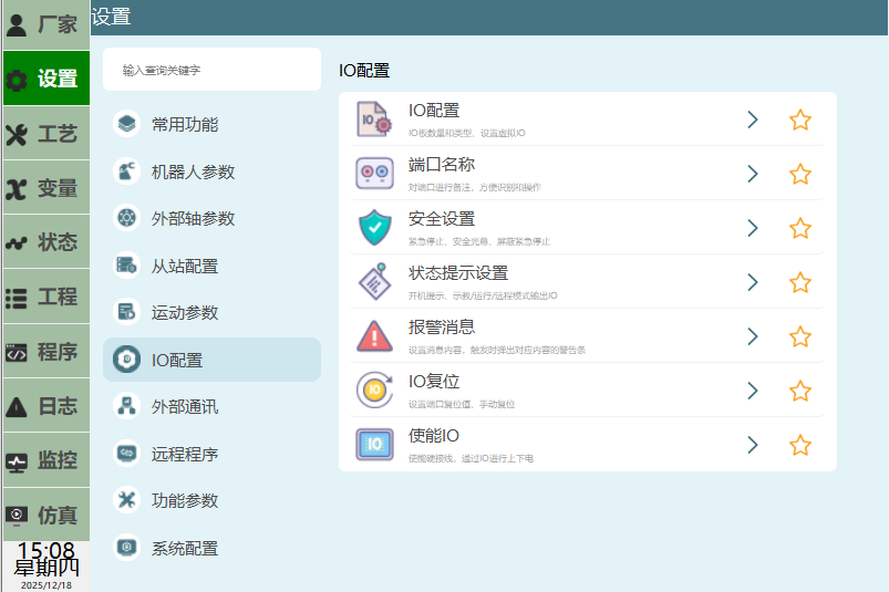
IO Configuration
See below:
IO Configuration
Configuration method see below:
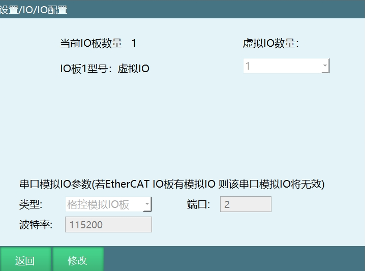
Click Settings - IO to enter IO configuration interface. This interface shows IO board count and current connected IO board model. Click [Modify] to set IO count, supports up to 4 IO boards.
Note: Virtual IO is for program debugging and demonstration only, no actual IO signals are connected.
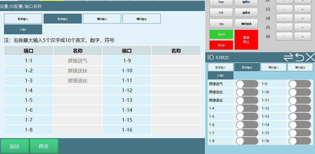
Port Name
Function: Define names for IO board digital and analog ports, convenient for users to know what IO ports represent when using multiple signals. For example, welding process uses many signals. After defining port names, you know what each port represents.
As shown, define port name. After save, port name is modified successfully.
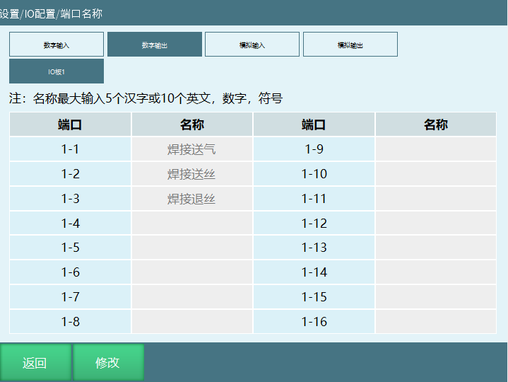
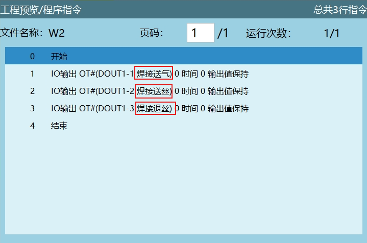
Corresponding port name modified in instructions:
Port name modified in Monitor - IO Status interface:
Safety Settings
Emergency Stop: After triggering emergency stop signal, robot powers off, servo status switches to stop.
Safety Curtain: Triggering safety curtain pauses robot. Press start button again to continue.
Secondary Start Confirmation:
- Remote mode: Give start signal first, then give secondary start confirmation signal, job file can run normally.
- Run mode: Press teach pendant start button first, then give secondary start confirmation signal, job file can run normally.
Mask Emergency Stop: After emergency stop is triggered, turn on enable to mask emergency stop signal.
Quick Stop Time: Robot quick stop time after emergency stop is triggered.
Mask Time: Signal mask time after emergency stop is triggered. During mask time, click clear error to move robot to safe position. After mask time expires, controller reports error (Robot mask ended, emergency stop was triggered).
Below is safety settings interface:
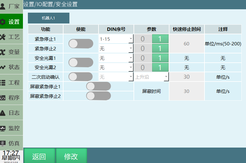
Example description: Set parameters as shown (parameters are for illustration only, no actual meaning):
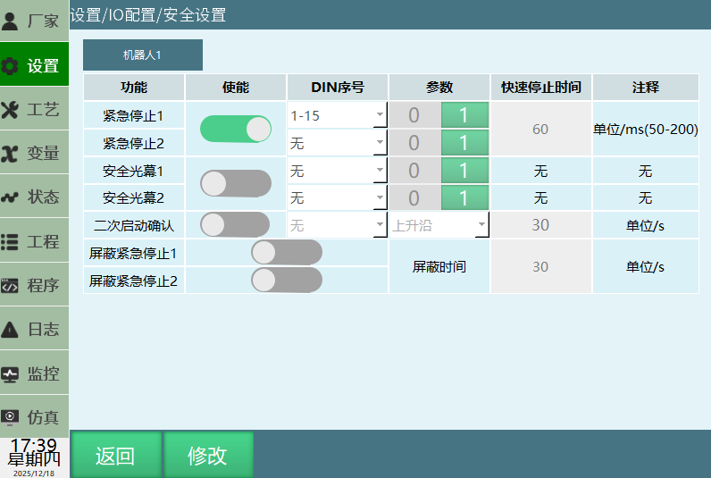
When IO port 1-15 changes from low 0 to high 1, emergency stop is triggered. Robot stops within the set 50ms.
Status Prompt Settings
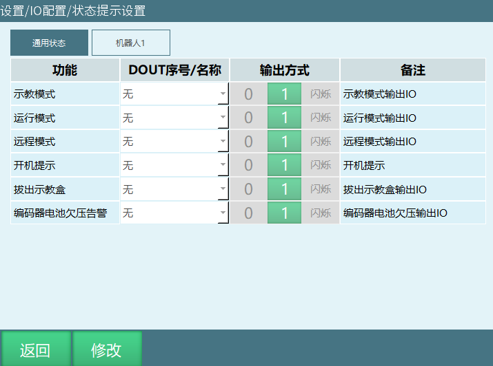
Output Method:
| Parameter | Description |
|---|---|
| 0 | Low level output prompt |
| 1 | High level output prompt |
| Blink | Selected IO blinks output prompt |
General Status:
- Startup prompt: IO output prompt when controller is in startup state.
- Teach mode: IO output prompt when current operation mode is teach mode.
- Run mode: IO output prompt when current operation mode is run mode.
- Remote mode: IO output prompt when current operation mode is remote mode.
- Remove teach pendant: IO output prompt after removing teach pendant.
Description: IO output port and output method for the following status output prompts based on user-set parameters.
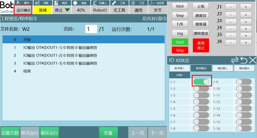
Example 1: Function select Run Mode; Output port 1-1; Output method 1.
When operation mode is run mode, IO port 1-1 outputs high level.
Robot Status Prompt:
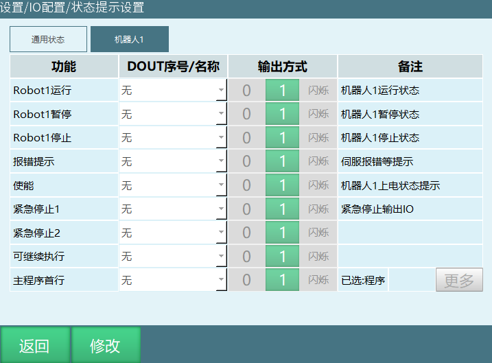
- Robot1 Running: IO output prompt when robot 1 program status is running.
- Robot1 Paused: IO output prompt when robot 1 program status is paused.
- Robot1 Stopped: IO output prompt when robot 1 program status is stopped.
- Error Prompt: IO output prompt when robot reports error.
- Enable: IO output prompt when servo is in powered state.
- Emergency Stop 1: IO output prompt after emergency stop 1 is triggered.
- Emergency Stop 2: IO output prompt after emergency stop 2 is triggered.
- Main Program First Line: IO output prompt when cursor jumps to "Main Program" first line.
- Can Continue: IO output prompt when running paused program.
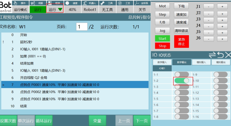
Example 2: Function select Robot1 Running; Output port 1-2; Output method 1.
When program is in running state, IO port 1-2 outputs high level.
Alarm Message
Click [Settings], select [IO Alarm Message] to enter interface. Users customize digital input and digital output alarm types and content.
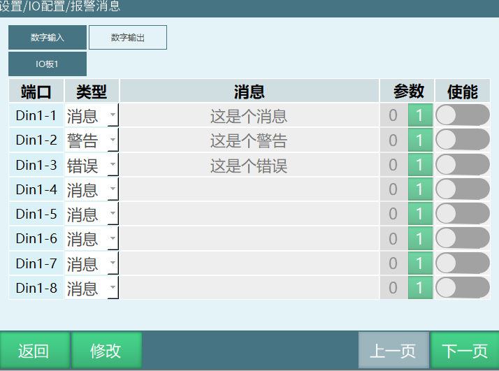
- [Port] IO port.
- [Type] IO alarm message output type (Message, Warning, Error).
- [Message] Content output after IO alarm is triggered.
- [Parameter] When set to 0, alarm message is triggered when IO port state is 0. When set to 1, alarm message is triggered when IO port state is 1.
- [Enable] Turn on enable switch, IO port reaching set state triggers alarm message. Turn off enable switch, no alarm message regardless of IO state.
Digital output alarm message parameter setting is the same as digital input. Below is example of digital input alarm message usage.
- Example 1: Port select Din1-1, Type select Message, message content "This is a message", Parameter 1, Enable on. As shown:
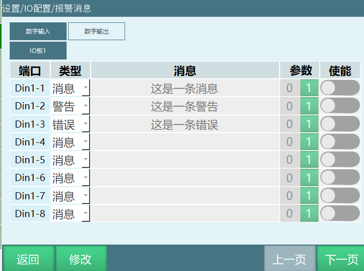
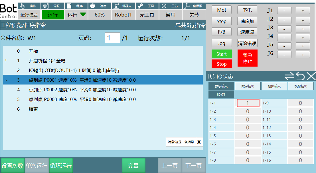
When input port 1-1 changes from low 0 to high 1, alarm message is triggered. Teach pendant shows white message prompt, program continues normally.
- Example 2: Port select Din1-1, Type select Warning, message content "This is a warning"; Parameter 1, Enable on. As shown:
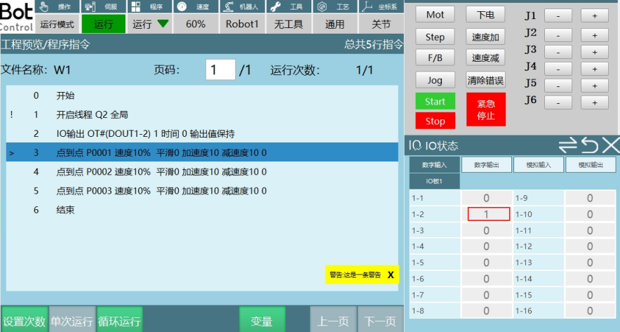
When input port 1-2 changes from low 0 to high 1, alarm message is triggered. Teach pendant shows yellow warning prompt, program continues normally.
- Example 3: Port select Din1-3, Type select Error, message content "This is an error", Parameter 1, Enable on. As shown:
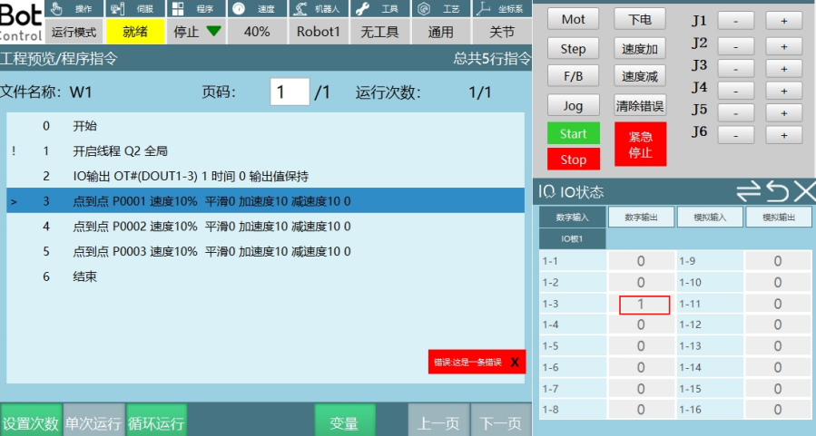
When input port 1-3 changes from low 0 to high 1, alarm message is triggered. Teach pendant shows red error prompt, servo powers off, program stops.
IO Reset
This function is based on signal output feedback after user performs IO reset operation, mode switch operation, or program error operation.
Description: After turning on reset enable, selected output port resets when performing IO reset, mode switch, or program error operations. Without turning on enable, output port cannot reset.
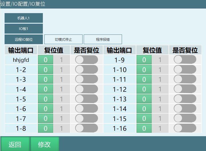
- Remote IO Reset: After performing IO reset in remote mode, after running to reset point or completing reset program, selected output port resets to reset value.
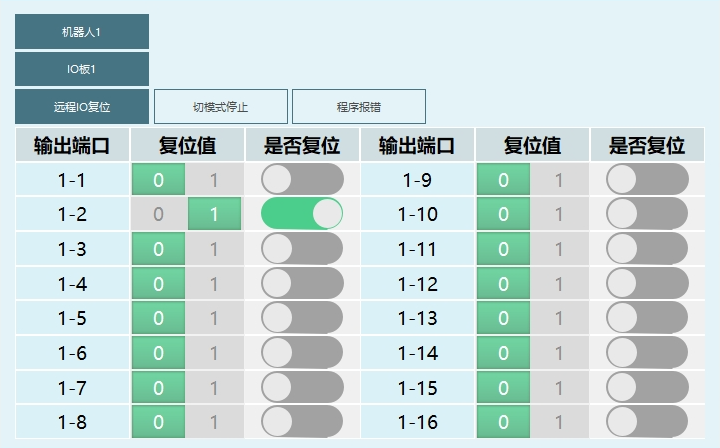
Example description: In remote mode, after robot runs to reset point or completes reset program, output port 1-2 resets. Reset value is 1.
- Mode switch stop: During program execution, switching modes causes program to stop. After mode switch operation, selected output port resets to reset value.
Example description: While running program in run mode, switch operation mode to teach mode. Selected reset output port is 1-1, reset value is 1, reset enable is on.
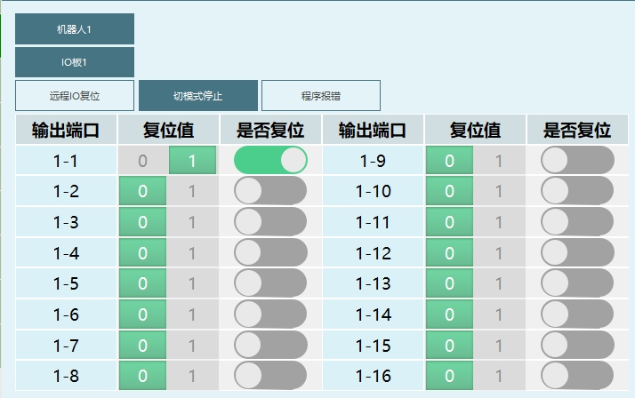
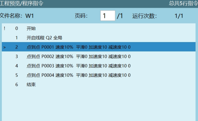
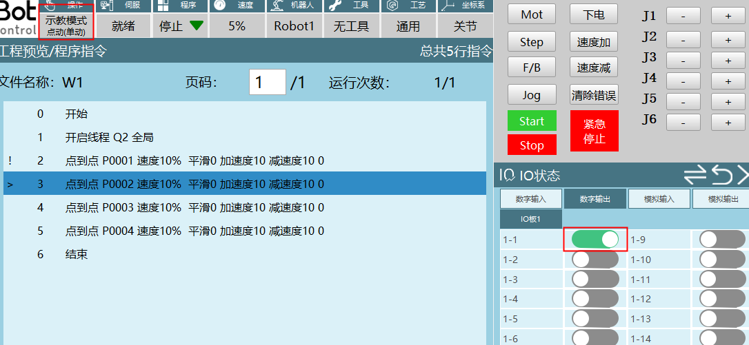
- Program error: During program execution, error causes program to stop. Output IO port resets to reset value.
Description: Only errors that clear breakpoints will trigger IO reset - program error.
Enable IO
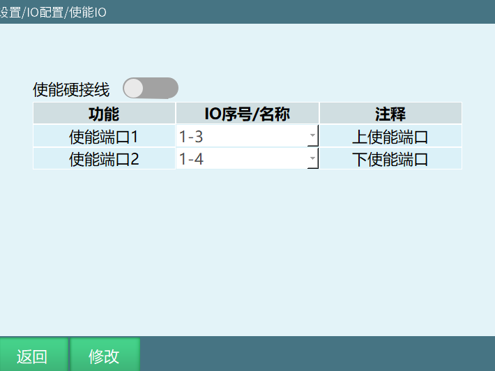
- If using hardwired enable teach pendant, after connecting cables, select corresponding DIN port on this page and turn on enable switch. Power-on enable function is controlled by IO board input signal. Do not set for non-hardwired enable teach pendant.
- After turning on this function, teach pendant enable button becomes invalid and cannot be used.
- Enable port 1 is power-on enable, enable port 2 is power-off enable.
- Power-on only requires turning on enable port 1. In any case, as long as enable port 2 is turned on, power-off will occur.
Robot Parameters
Tool Hand Calibration
Please refer to "Tool and User Calibration & Tool Hand Calibration" manual
User Coordinate Calibration
Please refer to "Tool and User Calibration & Tool Hand Calibration" manual
Robot Type
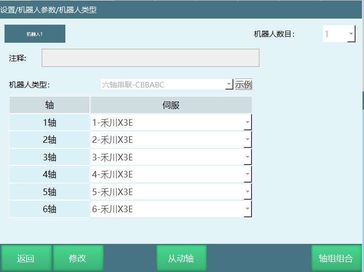
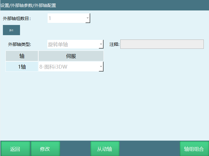
[External Axis]: Click [External Axis] to enter external axis configuration interface. In this interface, you can configure external axis group count and external axis type.
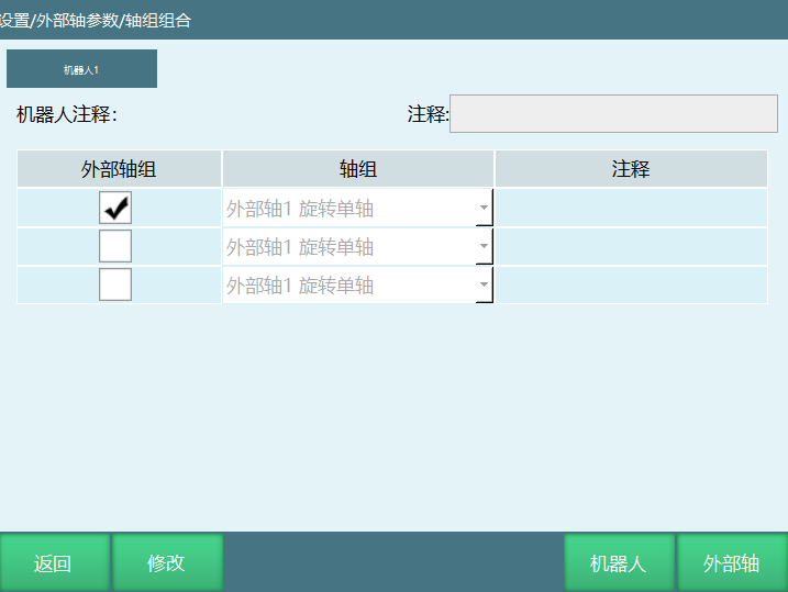
[Axis Group Combination]: Click [Axis Group Combination] to enter axis group combination configuration interface. In this interface, you can select external axis type.
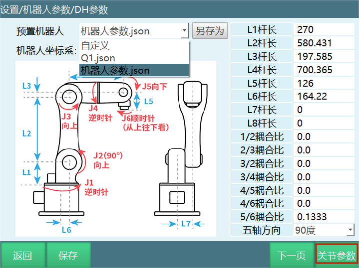
DH Parameters
Path: Settings - Robot Parameters - DH Parameters
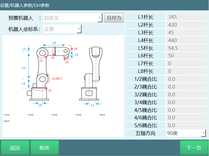
- Link length: All link length values are measured when robot is at zero position.
- Coupling ratio: During robot motion, when one joint moves, another joint also moves. This indicates coupling. To offset this coupling effect, coupling ratio is needed.
Coupling ratio = Follower axis rotation angle / Main axis rotation angle.
For example: Operating axis 1 to rotate 10 degrees, axis 2 follows rotating 15 degrees. Coupling ratio is 15/10=1.5.
- Five-axis direction: Five-axis direction when robot is at zero position.
- Three-axis direction (for 6-axis collaborative robot): 6-axis collaborative robot has two zero positions. Three-axis direction, five-axis direction (0,180), three-axis direction, five-axis direction (-90,90).
- Pitch (SCARA robot): SCARA robot's axis 3 controls lead screw up/down motion. Distance the lead screw moves when rotating axis rotates 360 degrees is the pitch.
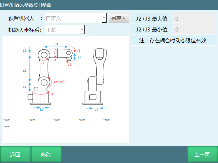
- J2+J3 maximum, J2+J3 minimum.
Dynamic limit only takes effect when axes 2/3 have coupling. When J2+J3 maximum and J2+J3 minimum are not within set parameter range, program execution will report error (Robot axes 2, 3 dynamic limit exceeded).
- Conversion ratio: Conversion ratio is the distance (unit: mm) traveled when joint rotates 360 degrees (also understood as motor rotating one revolution).
Conversion ratio calculation method: Fill conversion ratio as 1, then rotate corresponding axis 360 degrees, measure the distance traveled, fill in the measured distance.
For example: Motor rotation has angle value. Through conversion ratio, angle value can be converted to length value.
- Amplification ratio (4-axis palletizing lead screw): Tool end movement distance / Axis 3 lead screw movement distance.
- DH parameter interface added Save As parameter function, convenient for users to switch parameters.
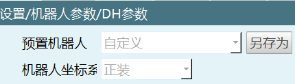
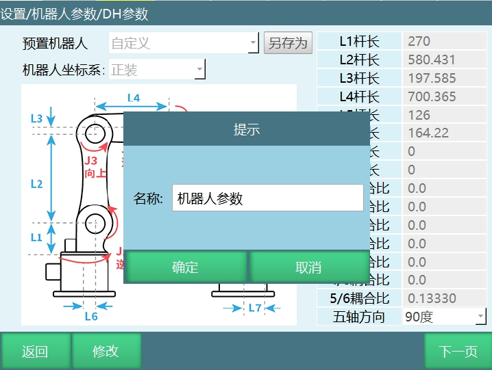
- Click [Save As], name the file as shown, click [OK].
Click preset robot to select preset parameter file. After clicking OK, users can modify DH parameters and joint parameters. Click [Joint Parameters] to enter joint parameters interface. If not needed, directly modify DH parameters in current interface.
Click [Save], user-modified parameters are saved to "Robot Parameters.json" file.
Joint Parameters
Path: Settings - Robot Parameters - Joint Parameters
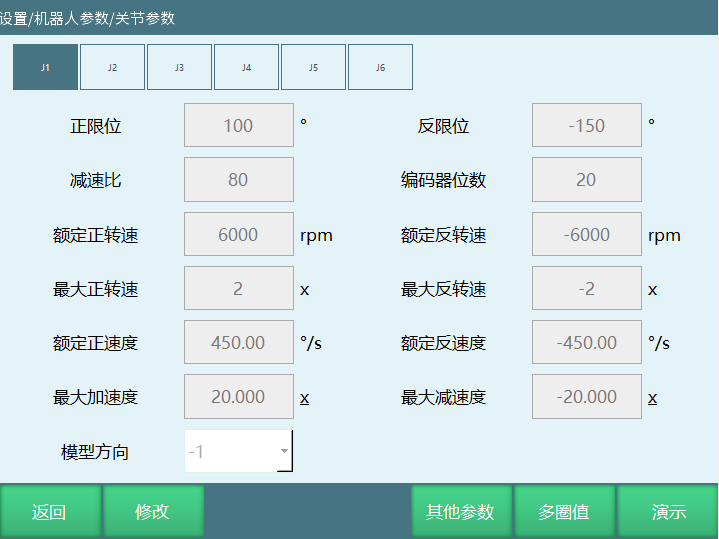
- Positive limit: Angle or distance robot rotates/moves in positive direction. Exceeding limit during motion reports error (Robot jog position reached limit).
- Negative limit: Angle or distance robot rotates/moves in negative direction. Exceeding limit during motion reports error (Robot jog position reached limit).
- Reducer ratio: Reducer's reduction ratio.
- Encoder bits: Fill in the encoder bits currently used. Do not fill randomly, otherwise robot will run away during jogging.
- Rated forward rotation speed: Motor's forward direction rotation speed.
- Rated reverse rotation speed: Motor's reverse direction rotation speed.
- Maximum forward rotation speed: For example, at 1x it takes 10 seconds to reach rated forward speed from 0. At 2x it takes 5 seconds.
- Maximum reverse rotation speed: For example, at 1x it takes 10 seconds to reach rated reverse speed from 0. At 2x it takes 5 seconds.
- Joint rated forward speed: Robot joint rated forward speed. Calculation: Rated forward rotation speed * 360 / 60 / Reducer ratio.
- Joint rated reverse speed: Robot joint rated reverse speed. Calculation: Rated reverse rotation speed * 360 / 60 / Reducer ratio.
- Maximum acceleration: For example, at 1x it takes 10 seconds to reach maximum acceleration from 0. At 2x it takes 5 seconds.
- Maximum deceleration: For example, at 1x it takes 10 seconds to reach maximum deceleration from 0. At 2x it takes 5 seconds.
- Model direction: Model direction can refer to zero position interface joint positive direction diagram. Each axis jog "+" key should match joint positive direction diagram. Same direction select 1, opposite select -1.
Other Parameters
Gear Backlash: Settings - System Configuration - Maintenance Mode interface has detailed description.
Multi-Turn Value
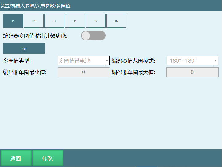
Encoder multi-turn value overflow count function: This function eliminates the impact of encoder max/min value jumps.
| Multi-Turn Value Type | Encoder Value Range Mode | Range |
|---|---|---|
| Multi-turn with battery | 1. -180°~180° | 1. Min [-2^31, 2^31], Max [-2^31, 2^31-1] |
| 2. 0°~360° | 2. Min [0, 2^32], Max [0, 2^32-1] | |
| Multi-turn without battery | 1. -180°~180° | 1. Min [-2^19, 2^19], Max [-2^19, 2^19-1] |
| 2. 0°~360° | 2. Min [0, 2^20], Max [0, 2^20-1] | |
| Single-turn | 1. -180°~180° | 1. Min [-2^19, 2^19], Max [-2^19, 2^19-1] |
| 2. 0°~360° | 2. Min [0, 2^20], Max [0, 2^20-1] |
For example: Encoder multi-turn value range is [-2147483648, 2147483647]. Current encoder multi-turn value position is 2147483647. Rotating 1 unit in positive direction becomes -2147483648. If system doesn't know encoder multi-turn value range, it will think robot suddenly jumped and doesn't know it actually only rotated 1 unit. This can easily cause runaway.

This parameter must be filled. Not filling may cause the following issues:
- Large position jumps, e.g., suddenly changing from 4 degrees to 40 degrees.
- Runaway.
- If configuring follower axis, follower axis encoder max/min values must also be filled!
Zero Position
Every coordinate system always has a point where all axes are 0, which is the coordinate system origin. For joint coordinate system, this point is called the zero position. That is, the position where robot's axes 1-6 values are all 0. As shown:
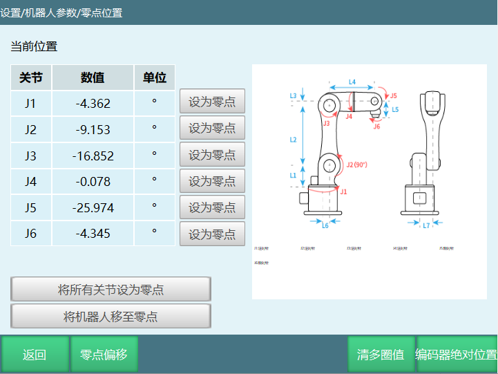
[Set as Zero]: Click to set a specific axis's zero position individually.
[Set All Joints as Zero]: Click to modify all axes' zero positions.
[Move Robot to Zero]: In teach mode with power on, click this button to move robot to zero position.
Zero Point Offset
Zero point offset can be used when users need to adjust zero point. Manually enter values.
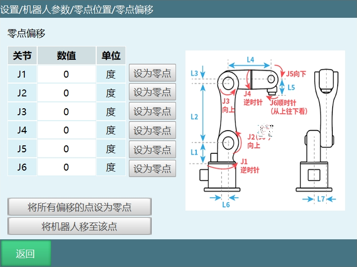
[Set as Zero]: Adjust a specific axis's zero position individually. Select the axis to adjust, manually enter value, click this button, then click [Return] in this interface to enter zero position interface. Click corresponding axis's [Set as Zero] to modify zero position.
[Set All Offset Points as Zero]: Adjust all axes' zero positions. Manually enter values then click this button, then click [Return] to enter zero position interface. Click [Set All Joints as Zero] to modify all axes' zero positions.
[Move Robot to This Point]: In teach mode with power on, click this button to move robot to zero position.
Clear Multi-Turn Value
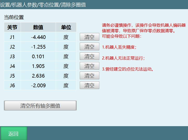
Multi-turn value is the number of servo motor revolutions.
Clear: Clear a specific axis's multi-turn value.
Clear All Axes Multi-Turn Value: Clear all axes' multi-turn values.
Encoder Absolute Position
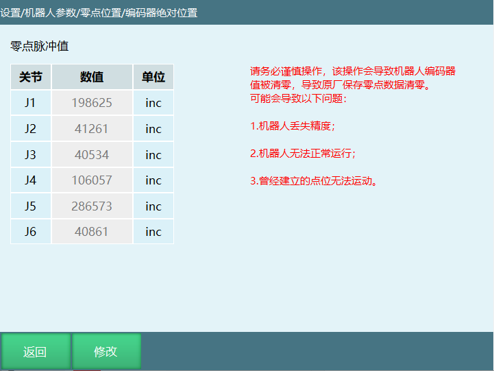
| Warning Message |
|---|
Please operate with caution. This operation will clear robot encoder values, causing factory-saved zero point data to be cleared! May cause the following issues: 1. Robot loses accuracy; 2. Robot cannot run normally; 3. Previously established positions cannot run. |
How to recover lost zero point?
Prerequisites:
- Robot only lost zero point due to operation error, collision cannot be recovered.
- Recorded single-turn value data before zero point loss (when multi-turn value not cleared, single-turn value interface shows last zero point calibration data).
Operation steps:
- Find the recorded single-turn value before zero point loss for backup.
- Teach robot to mechanical zero position.
- Clear robot all axes multi-turn values (this operation clears multi-turn and single-turn values, operate with caution).
- Calibrate robot all axes zero points.
- Enter recorded single-turn value data in single-turn value interface.
- Operate robot return zero to confirm zero point is correct.
Motion Parameters
Jog Parameters
Path: Settings - Motion Parameters - Jog Parameters
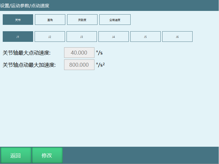
Joint maximum jog speed: Maximum speed when jogging robot in joint coordinates = Joint axis maximum jog speed * Global speed (teach pendant top status bar speed)
Cartesian maximum jog speed: Maximum speed when jogging robot in Cartesian coordinates = Cartesian maximum jog speed * Global speed (teach pendant top status bar speed)
Jog sensitivity: After power on, when robot jitter range exceeds jog sensitivity, jog operation is invalid.
Global speed: Range [1,100]. Users can define each speed segment.
Description: Speed increases in segments; Users can customize each segment name; Supports up to 20 speed segments.
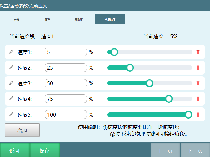
General Motion Parameters
Path: Settings - Jog Parameters - General Motion Parameters
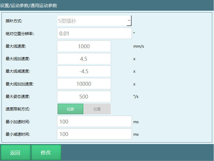
- Robot interpolation method: S-type, trapezoidal, jerk interpolation.
- Absolute position resolution: When running positions, if 2 points differ by less than resolution, they are treated as 1 point. For example: Set resolution to 0.01. GP0001 joint position (10, 0, 0, 0, 0, 0); GP0002 joint position (10.001, 0, 0, 0, 0, 0). When running these two positions, they are treated as one point.
- Maximum linear speed: Speed value filled here affects linear speed range. If maximum speed is 2000, when inserting a linear instruction, speed parameter maximum range becomes 2000. Maximum linear acceleration: Multiple of maximum linear speed. Larger target acceleration reaches target linear speed faster.
- Maximum linear jerk: Multiple of maximum linear speed. Larger target jerk reaches target linear speed faster.
- Maximum attitude speed: ABC axes maximum speed during robot motion. Exceeding limits speed.
- Speed limit method: Pose, Position Pose: During motion, consider position and attitude. Both position and attitude speeds do not exceed maximum speed limit. Position maximum speed limit: Instruction speed * Global speed Attitude maximum speed limit: Instruction speed * Global speed / Cartesian max linear speed * Maximum attitude speed
Position: Limit linear motion maximum speed. Attitude motion maximum speed is not limited.
- Minimum acceleration time: Minimum acceleration time refers to the shortest time required for robot to accelerate from static state to target speed, or from a lower speed to a higher speed. In practical applications, this is usually limited by robot drive system, such as servo motor torque and power. Rapid acceleration may cause motor overload or excessive vibration and noise, reducing robot lifespan or causing unstable motion.
- Minimum deceleration time: Minimum deceleration time refers to the shortest time required for robot to decelerate from maximum speed to static state, or from higher speed to lower speed. This is also limited by drive system capability, especially during high-speed deceleration. Motor needs to handle reverse torque and may need energy recovery or consumption to avoid overvoltage or overheating. In some cases, if deceleration is too fast, it may trigger safety mechanisms like emergency stop.
Role in robot operation:
- Responsiveness: In applications requiring quick response, such as obstacle avoidance or grasping unstable objects, minimizing these times can improve robot reaction speed.
- Safety: Controlling acceleration and deceleration can reduce impact from sudden changes, protecting robot and surrounding environment safety.
- Precision: In precision operations, appropriate acceleration and deceleration can improve positioning accuracy, avoiding errors from inertia.
- Energy Efficiency: Optimizing these parameters can reduce energy consumption, especially in applications with frequent starts and stops.
- Smoothness: By controlling acceleration/deceleration time, impact during motion can be reduced, making robot movements smoother and reducing stress on structures.
- In practical applications, robot controller dynamically adjusts acceleration and deceleration time based on motion planning, load conditions and safety requirements to achieve optimal motion effect.
Other Parameters
Path: Settings - Motion Parameters - Other Parameters
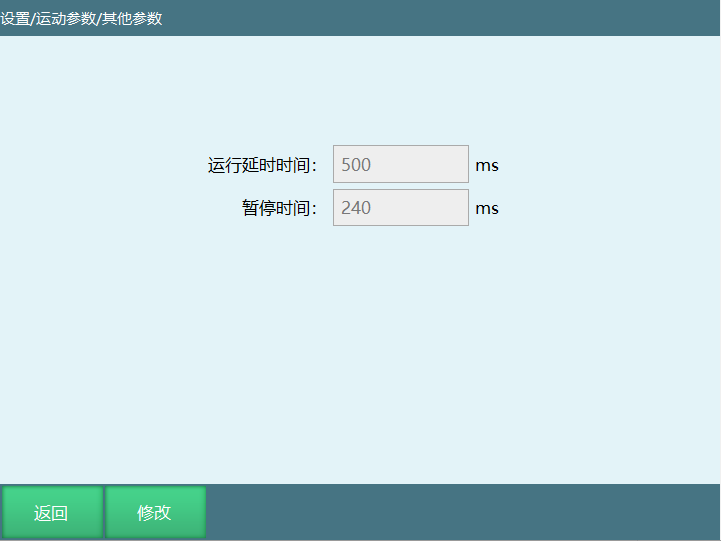
- Run delay time: Delay time when program starts. For example: Set delay time to 1000ms. Click start button, program starts after 1000ms delay.
- Pause time: Time from running to pause. For example: Set pause time to 500ms. Time for robot to stop motion when clicking pause button or other methods during program execution is 500ms.
Slave Configuration
Slave List
Path: Settings - Slave Configuration - Slave List
Slave list interface displays currently connected slave models, such as servo model, IO model.
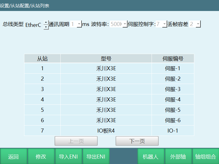
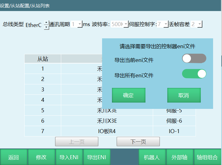
[Import ENI]: Import target ENI file.
Description: First time importing ENI requires creating an eni folder (folder name en-i-month-day) in USB root path, then place ENI file in the folder.
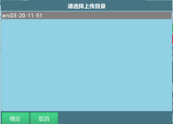
Click OK, popup as shown appears. Select needed ENI file, click OK. After ENI file import succeeds, restart system.
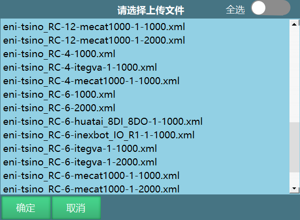
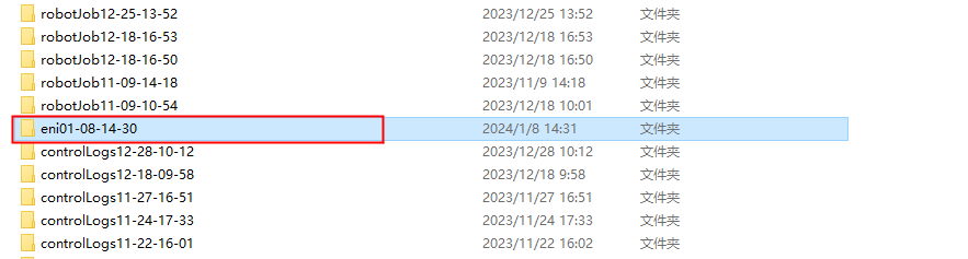
[Export ENI]: Insert USB drive into teach pendant USB port, click [Export ENI]. Can select export current ENI or export all ENI. After ENI file export succeeds, saved to USB root path. Folder naming: eni + specific date, as shown.
[Robot]: Click Robot to enter robot configuration interface. In this interface, modify robot count and robot type.
[External Axis]: Click [External Axis] to enter external axis configuration interface. In this interface, configure external axis group count and external axis type.
[Axis Group Combination]: Click [Axis Group Combination] to enter axis group combination configuration interface. In this interface, select external axis type.
Slave Parameters
Path: Settings - Slave Configuration - Slave Parameters
Below is Dechuang servo parameter interface.
Description: Not all servos support modifying/reading parameters in this interface.
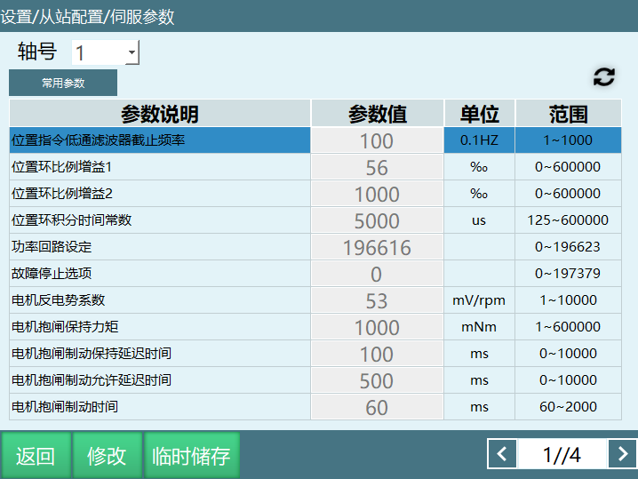
| Warning Message |
|---|
Please modify with caution. After modification, test in safe area! |
Servo Settings
Path: Settings - Slave Configuration - Servo Settings
Detection period: How often to check if the three parameters have abnormalities.
Tracking error: During motor motion, the difference between position command and actual position from start of motion to actual position. Difference between target position and actual position is called tracking error.
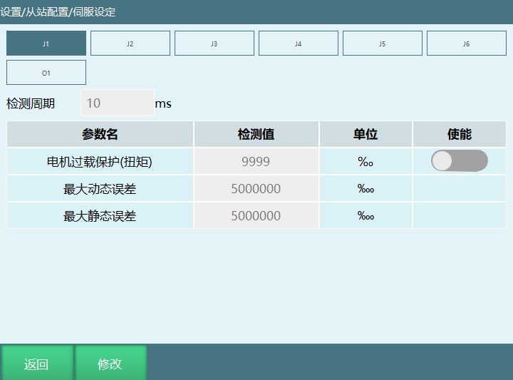
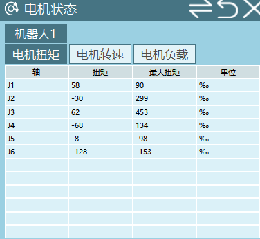
Motor overload protection: This interface sets motor torque overload threshold. Unit permille and mNm (based on Settings - Maintenance Mode - Parameter Selection interface motor load parameter unit setting).
Motor overload protection enable: Motor overload protection switch. Takes effect after turning on.
Note: Current torque and maximum torque can be viewed in monitor interface.
Function Parameters
Background Task
Path: Settings - Function Parameters - Background Task. Background tasks are divided into global background and local background.
Local Background
[Return]: Click "Return" to exit background task interface.
[New]: Click "New" to create program or folder. Select desired new type program/folder, enter name in name box and click [OK]. Program/folder created successfully.
[Open]: Select job file and click "Open". After opening, can insert instructions, modify instructions, delete instructions for current job file.
Description: If opening a folder, can create new programs inside the folder.
[Operations]: Selected job file can perform batch mode/single line mode operations, such as move, copy, delete.
Description: If selected is folder, click Operations only has copy, delete, rename, batch delete. If selected is program, click Operations has move, copy, delete, rename, batch delete and encrypt.
Run local background program:
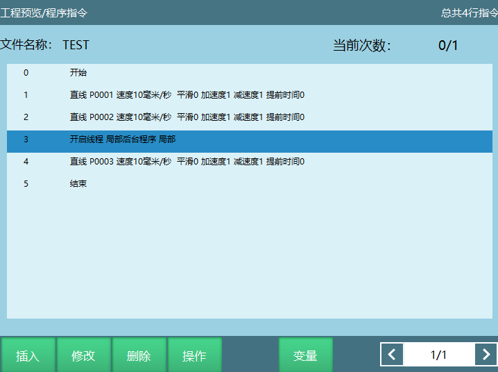
- Single step run background program in teach mode;
- Foreground calls background program (foreground job file inserts thread start instruction).
Global Background
[Return]: Click "Return" to exit background task interface.
[New]: Click "New" to create program or folder. Select desired new type program/folder, enter name in name box and click [OK]. Program/folder created successfully.
[Open]: Select job file and click "Open". After opening, can insert instructions, modify instructions, delete instructions for current job file.
Description: If opening a folder, can create new programs inside the folder.
[Operations]: Selected job file can perform batch mode/single line mode operations, such as move, copy, delete.
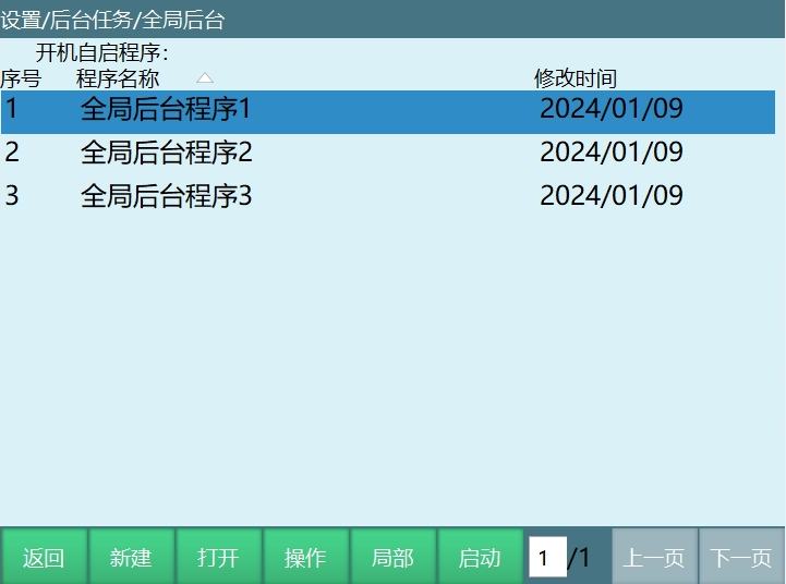
Description: If selected is folder, click Operations only has copy, delete, rename, batch delete. If selected is program, click Operations has move, copy, delete, rename, batch delete, set as auto-start and encrypt.
Description: Select target program, click [Operations] select Set as Auto-Start. In current interface, after "Auto-start program" the current auto-start program's job file name is displayed.
[Start]: Start the global background program set as auto-start.
Global background program execution:
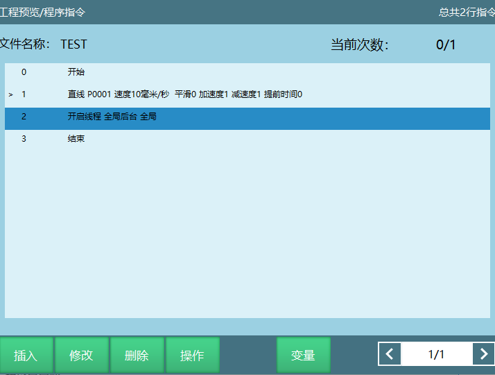
- Single step run in teach pendant mode;
- Target program set as auto-start. After startup, background program runs directly;
- Foreground calls background program (foreground job file inserts thread start instruction).
Reset Point Settings
Path: Settings - Function Parameters - Reset Point Settings
Click teach pendant "Reset" button to move robot to reset point.
Click Monitor - Shortcut Keys - Return Safety Point to move robot to reset point.
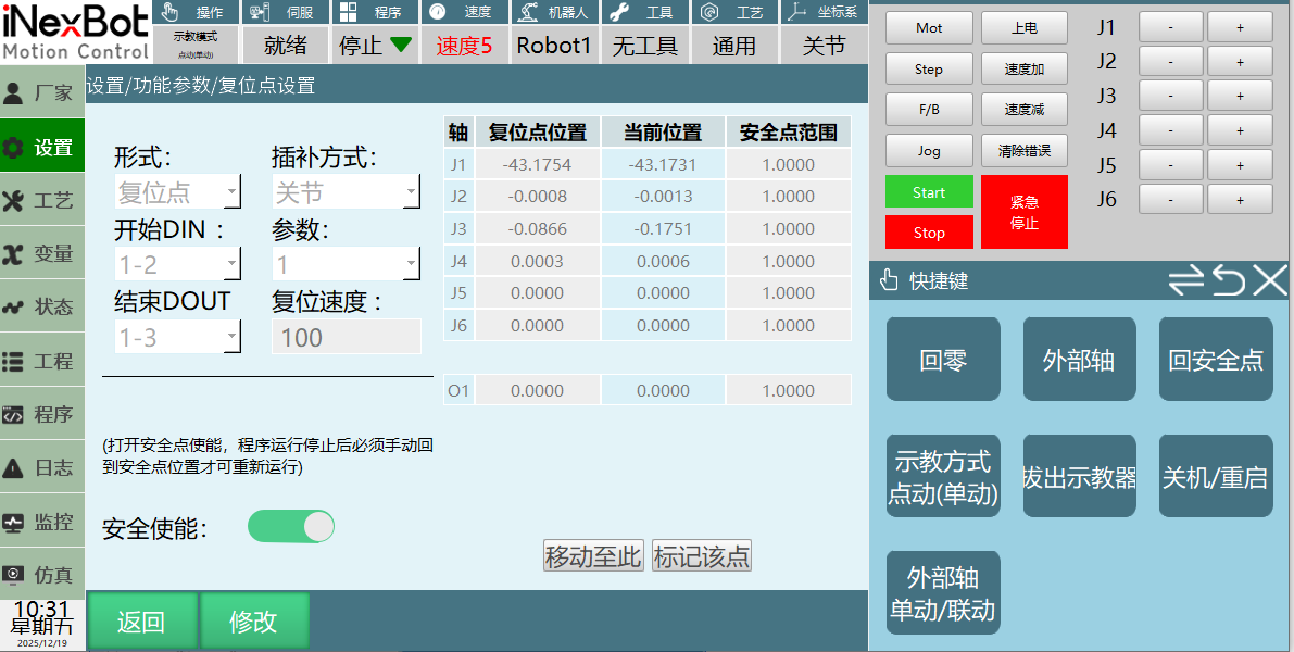
Form: Reset point, Reset program:
- Reset point: After robot moves to target reset point, click [Mark This Point], click [OK] to mark reset point successfully. In teach mode, click reset button to move robot to set reset point position.
As shown, clicking reset moves robot to reset point position (-43.1754, -0.0008, 0.0866, 0.0003, 0, 0).
- Reset program: After user inserts instructions, click reset to start running reset program.
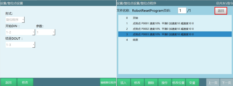
- Set parameters, click [Edit Reset Program];
- After inserting target instructions, click "Return" in reset point program interface to exit. Cannot exit without clicking "Return".
- Reset point position: Recorded reset point position.
- Current position: Robot's current actual position.
- Safety point range: Range [-10,10]. Turn on safety enable. In run mode running program, if current position is not within safety point range, cannot run program. Need to switch to teach mode to manually return to safety point before running program again.
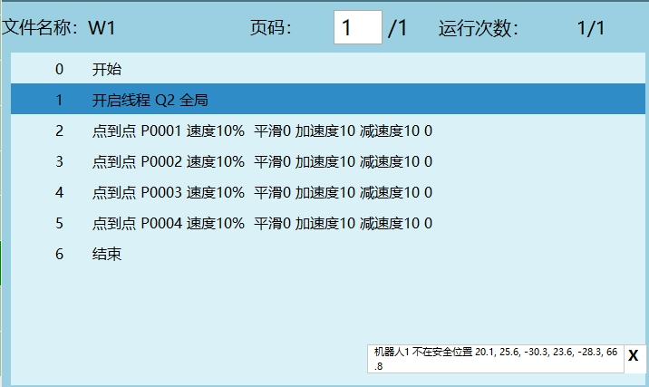
Description: In teach mode and remote mode, turning on safety enable has no effect on program execution.
- Mark This Point: After robot moves to target point, click "Mark This Point", click "OK" to mark reset point successfully.
- Move to This: In teach mode, click "Move to This" to move robot to reset point.
- Interpolation method: Joint interpolation, Linear interpolation.
- Reset speed: Setting reset point speed auto-calculates acceleration (refer to instruction input speed auto-calculating acceleration). Actual reset speed = Reset speed * Global speed. When interpolation method is joint interpolation, range 1-100%; When interpolation method is linear interpolation, range based on Cartesian parameters.
- Start DIN: Set IO input signal. In remote mode, after giving signal, robot moves to reset point or reset program.
- Parameter: 0, 1 (low level start, high level start).
- End DOUT: Signal feedback after robot runs to reset point in remote mode. Assume output signal is 1-3. After robot runs to reset point, IO port 1-3 changes from low to high.
Description: IO start reset only supports remote mode.
Interference Zone
Calibrated X, Y, Z define space range. Based on calibrated space range, users can select to restrict robot motion inside or outside the area. As shown:
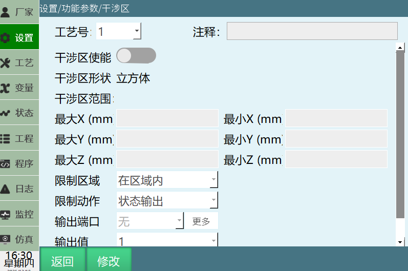
Determining interference zone range can be done by directly filling parameters or moving robot to calibrate range.
- Fill parameters;
- Click [Modify] and fill values in corresponding parameter rows;
- Turn on interference zone enable, click [Save]. Interference zone range setting complete.
- Move robot to calibrate;
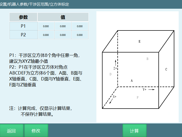
- Click [Calibrate] - page jumps to calibration page;
- Click [Modify] on calibration page;
- Move robot, select [P1], click [Calibrate];
- Move robot, select [P2], click [Calibrate];
- Click [Save] - [Calculate];
- Turn on interference zone enable, click [Save]. Interference zone range setting complete.
Interface parameter description:
| Parameter | Description |
|---|---|
| Craft Number | Can select 9 craft numbers, can use multiple simultaneously |
| Interference Zone Enable | Turn on interference zone enable for set range to take effect |
| Min X | Motion range X axis minimum |
| Max X | Motion range X axis maximum |
| Min Y | Motion range Y axis minimum |
| Max Y | Motion range Y axis maximum |
| Min Z | Motion range Z axis minimum |
| Max Z | Motion range Z axis maximum |
| Restricted Area | Inside interference zone or outside interference zone |
| Restricted Action | Status output: Trigger status output when robot is inside or outside interference zone Prohibit motion: Prohibit robot operation when robot is inside or outside interference zone |
| Output Port | IO output port number or GB variable |
| Output Value | 0 or 1 |
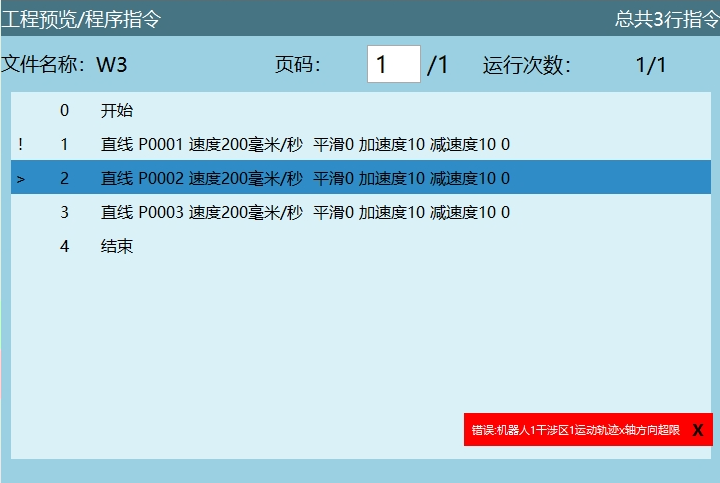
Example 1 (Inside area prohibit motion): When robot enters interference zone during operation, reports error, servo powers off, robot stops. As shown:
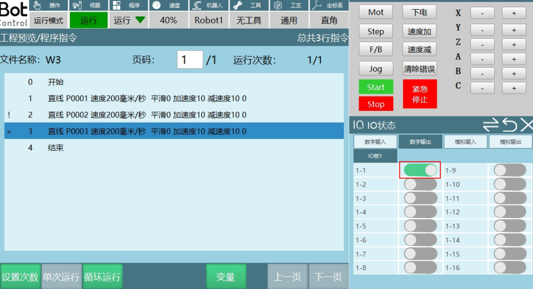
Example 2 (Inside area status output): When robot moves to interference zone, IO port outputs prompt. See below:
Collaborative Robot
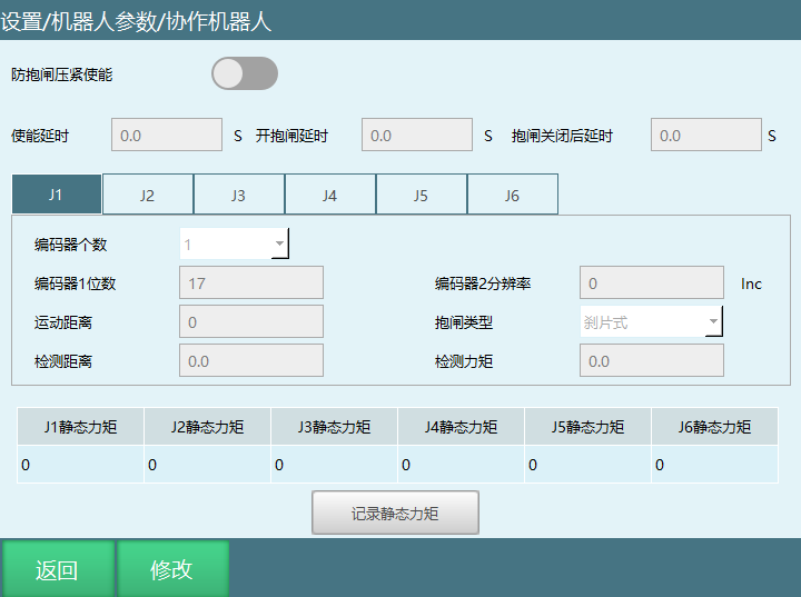
Path: Settings - Function Parameters - Collaborative Robot
Below is collaborative robot parameter setting interface. Other robot types cannot enter this interface.
Enable delay: After pressing enable key, delay before sending enable command to servo.
Brake release delay: After sending enable command, delay before sending brake release command to servo.
Brake close delay: After brake closes, delay before servo responds to next operation.
Encoder count: Single joint encoder count.
Encoder 1 bits: Same as encoder bits in joint parameters.
Encoder 2 resolution: Another encoder's inc value in single joint.
Motion distance: Micro-motion distance before brake release. Generally 20. This value is encoder value, unit inc.
Brake type: Friction brake and pin brake. This value is encoder value, unit inc.
Detection distance: After brake release, joint motion distance used to detect if brake is open.
Detection torque: After brake release, if torque exceeds detection torque during joint running detection distance, brake open is considered failed.
Sub-Function
See "Instruction Set" - Sub-Function
Custom Button
Path: Settings - Function Parameters - Custom Button
Function description: Supports user custom binding buttons to control robot motion and IO port output.
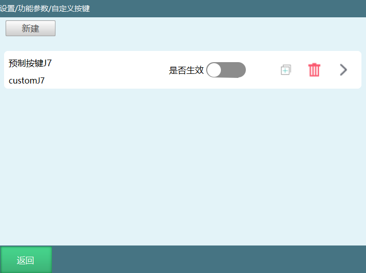
Click [New] or [+] to enter custom button configuration interface.
Enable: Turn on switch to execute corresponding binding function.
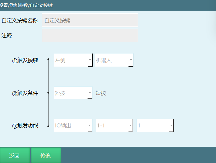
Custom button name: Users can define name for binding button.
Comment: Binding button description comment.
| Trigger Button | Teach pendant left side: Robot button, External axis button, Zero point button, Reset button and Drag button Teach pendant bottom: F/B button, V- button, V+ button, Tool button and Coordinate button Right side: J1+ key/J1- key ------ J7+ key/J7- key | ||
|---|---|---|---|
| Trigger Condition | Long press | Range [100,5000]ms How many ms to hold button to trigger corresponding function | Trigger: After clicking button, stays in trigger state Description: Trigger port 1-1 (assume port initial state low). Trigger button is robot button. Click robot button, port 1-1 opens and stays open (high) Active: Click button function triggers, release button function releases Description: Trigger port 1-1 (port initial state low). Trigger button is robot button. Click robot button, port 1-1 opens (high). Release robot button, port 1-1 closes (low) |
| Short press | Click button once to trigger corresponding function | ||
| Trigger Function | IO Output | 0: Port high state, click binding button, port changes from high to low, selected output port closes 1: Port low state, click binding button, port changes from low to high, selected output port opens Toggle: After clicking binding button, selected output port high/low toggles | |
| Move to Point | Supports binding GP point and GE point |
Note: Same trigger method cannot exist for the same button insertion.
Program Auto-Start
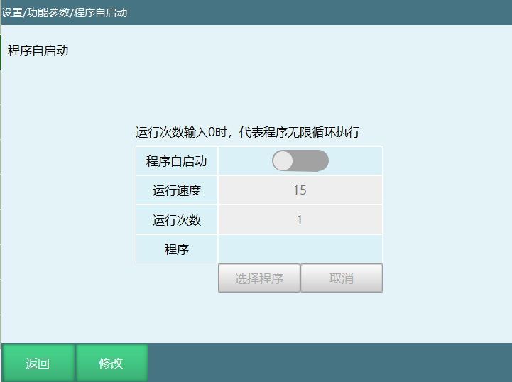
Path: Settings - Function Parameters - Program Auto-Start
Click [Modify] to select program, turn on program auto-start switch. Selected program auto-starts on boot.
Note: If program auto-start is set, operators must stay away from robot on every boot. Interface as shown:
Arch Parameter Table
Path: Settings - Function Parameters - Arch Parameter Table
Click [Modify] to edit vertical rise distance and vertical fall distance values, unit mm.
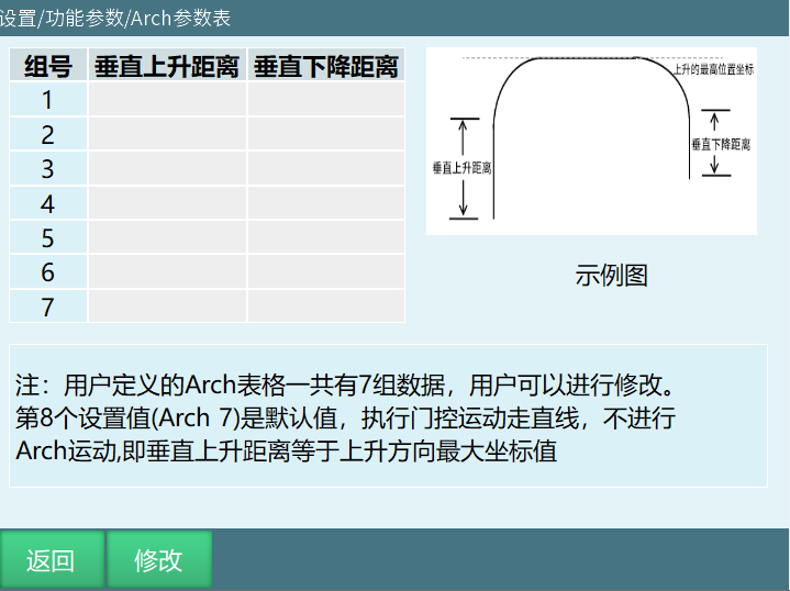
Group Number: Arch parameter table supports 7 groups of data.
Vertical Rise Distance: Distance rising vertically from start point, unit mm.
Vertical Fall Distance: Distance falling vertically from target point, unit mm.
Note: Can directly call this parameter table when using arch motion instruction & extended arch instruction.
Calibrate Ground Coordinate System
Path: Settings - Function Parameters - Calibrate Ground Coordinate System
Function: Calibrate slave robot's user coordinate system based on master robot.
Notes:
- Two robot arms must be very close so some work areas overlap.
- Before using relative calibration, tool hand must be correctly calibrated for both robots.
- During calibration process, recommend calibrating multiple points. More calibration points means higher accuracy.
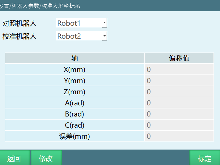
Click [Modify]. If deviation value is known, can select manual value.
Click [Calibrate], follow prompt steps to calibrate.
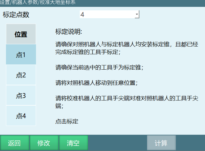
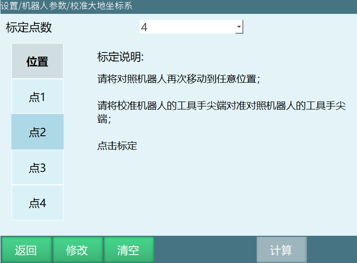
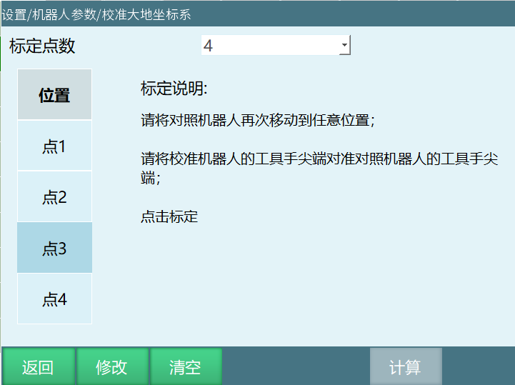
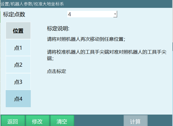
Click [Save] first, then can click [Calculate].
Q&A for Retrieval
Q: What is encoder multi-turn value overflow count function?
A: Encoder multi-turn value overflow count function eliminates the impact of encoder max/min value jumps, avoiding robot runaway.
Q: What encoder value range modes are available?
A: Two encoder value range modes: -180°~180° and 0°~360°.
Q: What is zero position?
A: Every coordinate system has a point where all axes are 0, which is the coordinate system origin. For joint coordinate system, this point is called zero position, the position where robot's axes 1-6 values are all 0.
Q: How to set zero position?
A: Click [Set as Zero] to set a specific axis's zero position individually; Click [Set All Joints as Zero] to modify all axes' zero positions; Click [Move Robot to Zero] with power on in teach mode to move robot to zero position.
Q: What is interference zone?
A: Interference zone is the restricted area of robot motion range. Setting interference zone can restrict robot motion within specific range or trigger status output.
Q: What restricted actions does interference zone have?
A: Two restricted actions: Status output (trigger status output when robot is inside or outside interference zone) and Prohibit motion (prohibit robot operation when robot is inside or outside interference zone).
Q: How to configure custom button?
A: Click [New] or [+] to enter custom button configuration interface. Set trigger button, trigger condition and trigger function. Turn on enable switch.
Q: What trigger conditions does custom button have?
A: Custom button trigger conditions are Long press (range [100,5000]ms) and Short press (click button once to trigger function).
Q: What trigger functions does custom button have?
A: Custom button trigger functions are IO Output (port high/low toggle) and Move to Point (supports binding GP and GE points).
Q: How to set program auto-start?
A: Path: Settings - Function Parameters - Program Auto-Start. Click [Modify] to select program, turn on auto-start switch. Selected program auto-starts on boot.
Q: How many groups of data does Arch parameter table support?
A: Arch parameter table supports 7 groups of data, including vertical rise distance and vertical fall distance, unit mm.
Q: How to calibrate ground coordinate system?
A: Click [Modify]. If deviation value is known, can select manual value; Click [Calibrate], follow prompt steps; Click [Save] first, then can click [Calculate].
Q: What is the difference in backup program names across platforms?
A: Version 2403 and above modified controller & teach pendant startup program names for different platforms. For example, C1102 original program was nrc.out/nrc2.out, current program is C1102_X86_Linux-RT1_Robot-controller, etc.
Version History
| Version | Date | Changes | Author |
|---|---|---|---|
| 1.0.0 | 2026-06-29 | Initial version | FDJAK |