Laser Cutting Process
Process Introduction
The laser cutting process is divided into two parts: piercing and cutting. The cutting process will first perform piercing. Piercing-related parameters and cutting mode parameters are set in global variables. Cutting gas pressure, power, and other parameters are set in cutting variables. Cutting and piercing have no physical difference; they are distinguished only for better cutting results. Piercing is to ensure that the material can be penetrated at non-edge positions to avoid incomplete cutting, and to reduce laser efficiency during subsequent cutting to achieve energy-saving goals.
During the cutting process, continuous air blowing is performed. Its purposes are twofold: first, to blow away residue generated during cutting to ensure smooth and clean cut surfaces; second, to improve cutting efficiency. The oxygen concentration of the blown gas affects cutting efficiency. Within a safe range, higher concentration means higher cutting efficiency.
Combined with offline programming, complex trajectory cutting can be achieved.
Global Parameters
Open the teach pendant, enter the "Process" interface, select "Laser Cutting Process", and enter the "Global Parameters" interface.
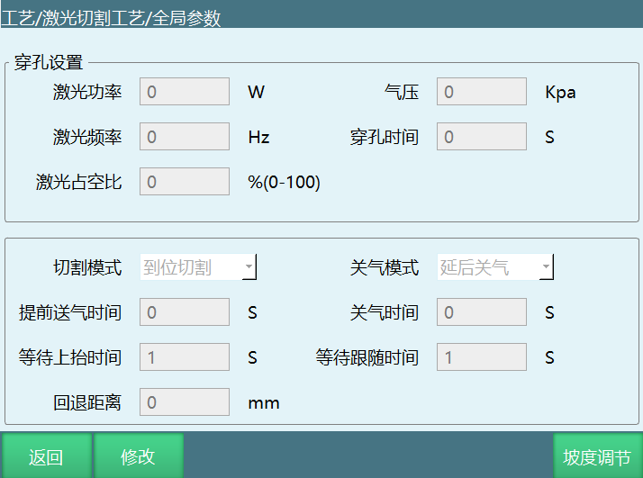
Global parameters interface parameter description:
- Piercing Settings:
- Laser Power: Laser power during piercing, measured in W. Higher power results in higher piercing efficiency, but also rougher cut surfaces.
- Gas Pressure: Gas pressure output size. Gas pressure controls cleaning residue on the back of the cut to ensure smooth and clean cut surfaces.
- Laser Frequency: Number of laser pulses emitted per second.
- Piercing Time: Duration of piercing after the laser starts. The duration must ensure the current workpiece is penetrated.
- Laser Duty Cycle: Proportion of laser operation within a unit of time. For example, 66% means the laser operates for 0.66 seconds within one second.
- Cutting Mode:
- Position Cutting: Run the cutting trajectory after piercing reaches position.
- Direct Cutting: No piercing, directly run the cutting trajectory.
Gas Shutoff Mode:
- Delayed Gas Shutoff: Close air blowing after laser cutting ends.
- Early Gas Shutoff: Close air blowing before laser cutting ends.
Gas Shutoff Time: Based on the set gas shutoff mode, the early or delayed gas shutoff time.
Early Gas Delivery Time: How much time before laser cutting starts to begin gas delivery.
Wait for Lift Time: How long to wait after laser cutting is complete before lifting.
Wait for Follow Time: After sending the follow signal, the maximum wait time for the follow-in-place signal.
Retract Distance: Retract distance when laser cutting is interrupted and then continues.
Note: After receiving the follow-in-place signal, the robot immediately starts running along the cutting trajectory. If the follow-in-place signal is not received within the set time, the system will trigger a laser cutting follow-in-place timeout error.
Cutting Parameters
Open the teach pendant, enter the "Process" interface, select "Laser Cutting Process", and enter the "Cutting Parameters" interface.
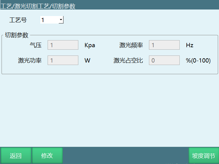
Process Number: Save multiple parameter sets that can be called in instructions.
Gas Pressure: Gas pressure during cutting.
Laser Power: Laser power during cutting.
Laser Frequency: Number of laser pulses emitted per second.
Laser Duty Cycle: Proportion of laser operation within a unit of time. For example, 66% means the laser operates for 0.66 seconds within one second.
Analog Matching
Enter the "Process" interface, select "Laser Cutting Process", and enter the "Analog Matching" interface.
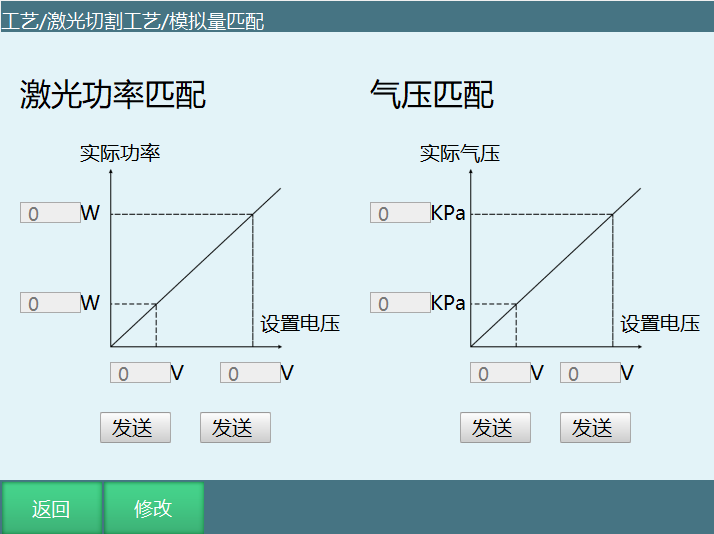
Usage is the same as welding current/voltage matching. The system calculates the proportionality coefficient based on the set voltage value and actual power/pressure values.
IO Settings
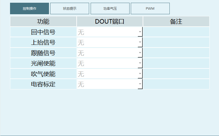
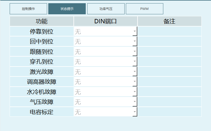
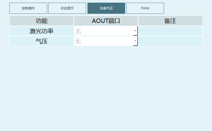
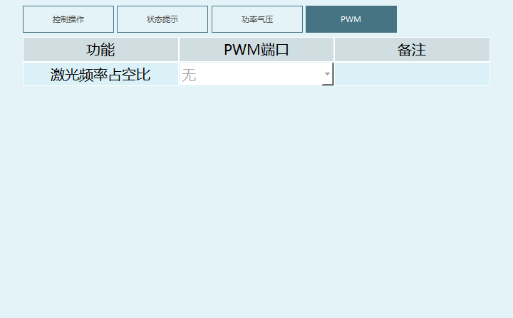
Divided into 4 parts: Control Operations, Status Indicators, Power/Pressure, and PWM. The specific interface for each part is shown in the figures below.
- Control Operations:
Home Signal: When the corresponding signal is output, the laser returns home.
Lift Signal: When the corresponding signal is output, the laser lifts up.
Follow Signal: When the corresponding signal is output, the laser starts following.
Shutter Enable: When the corresponding signal is output, the shutter opens.
Air Blow Enable: When the corresponding signal is output, air blowing starts.
Capacitance Calibration: When the corresponding signal is output, check if a return signal indicates successful calibration.
- Status Indicators:
Docking Position: When the height adjuster stops at position, the corresponding port will have an input signal.
Home Position: When the height adjuster returns home, the corresponding port will have an input signal.
Follow Position: When the height adjuster follows to position, the corresponding port will have an input signal.
Piercing Position: When laser cutting piercing reaches position, the corresponding port will have an input signal.
Laser Fault: When a laser fault occurs, the corresponding port has an input signal and triggers an error stop.
Height Adjuster Fault: When a height adjuster fault occurs, the corresponding port has an input signal and triggers an error stop.
Water Cooler Fault: When a water cooler fault occurs, the corresponding port has an input signal and triggers an error stop.
Gas Pressure Fault: When a gas pressure fault occurs, the corresponding port has an input signal and triggers an error stop.
Capacitance Calibration: When the height adjuster returns the corresponding signal, calibration is successful.
- Power/Pressure:
Laser Power: Analog output port controlling laser power. Controls actual output based on analog output.
Gas Pressure: Analog output port controlling gas pressure. Controls actual output based on analog output.
PWM:
Laser Frequency Duty Cycle: Can be switched between two ports based on the R4PWMIO board. Only boards with PWMIO can select ports.
Manual Operations
Laser:
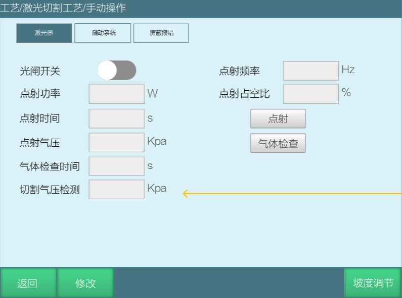
Shutter Switch: Similar to welding enable, the shutter must be opened for the laser to emit. The shutter switch must be manually opened, otherwise it will not open automatically.
Test Fire Power: Laser power during test fire.
Test Fire Time: Single test fire duration.
Test Fire Gas Pressure: Gas pressure during test fire.
Gas Check Time: Single gas check duration. Repeated checks within this time will trigger a prompt.
Test Fire Frequency: Number of laser pulses emitted per second during test fire.
Test Fire Button: Used for debugging laser parameters. After setting the corresponding IO, clicking can emit light for adjustment.
Gas Check: Used for debugging laser parameters. After setting the corresponding IO, gas pressure checks can be performed for adjustment.
Cutting Gas Pressure Check: When cutting gas pressure check is set to equal or greater than the value below, normal emission occurs. If less, an alarm is triggered. For example, if cutting gas pressure check is set to 200Kpa, when gas is output, the cutting gas pressure will be checked. The laser will only emit when the pressure reaches 200Kpa or above. If below 200Kpa, an alarm will be triggered: Gas pressure has not reached the set value, cutting cannot begin.
Specific interface is shown in the figure below:
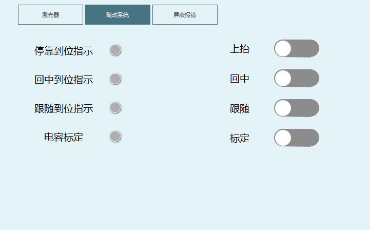
Height Following System:
Lift, Home, and Follow buttons control the laser. They need to have IO bound before use. When in position, the status indicator will turn green.
Capacitance Calibration: Newly added capacitance calibration. Calibration requires the previous IO input/output to be set and the height adjuster to be able to return input normally. After successful calibration, the status indicator will turn green.
As shown below:
Suppress Alarm:
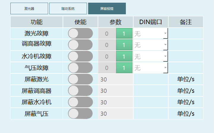
When the corresponding fault is triggered, the robot will stop, and the suppress alarm enable can only be opened after the corresponding alarm is triggered. Set the suppress alarm time as needed. During this time, move the robot to clear the alarm. After the set suppress time expires, if the alarm signal still exists, another alarm will trigger power off. As shown below:
Instruction Description
Laser Start
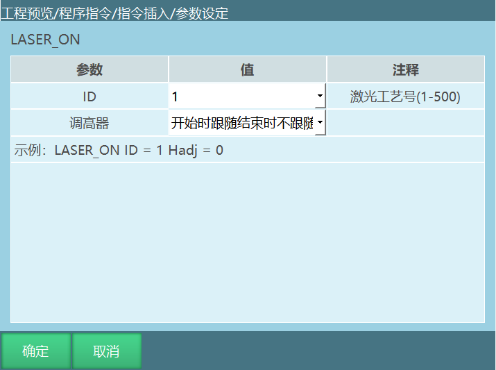
Note: The height adjuster follow option is a dev feature, not available in 2403.
Format: LASER_ON [Instruction Name] ID=1 [Process Number] Height Adjuster=Follow at start, don't follow at end [Height Adjuster Follow Option].
Function: Start cutting after reaching the cutting start point.
Parameters are shown in the table:
| ID | Laser cutting process number, range (1,500) |
|---|---|
| Height Adjuster | Follow at start, don't follow at end Needs to receive the follow-in-place signal to continue running. Must be used with End Follow in laser end. If the laser end height adjuster option selects Continue Follow without emission, a mismatch prompt will appear and End Follow will be used by default. This mode sends the follow signal and opens air blow enable when starting, runs the next instruction after receiving the follow-in-place signal, and closes the follow signal and air blow enable at the end. |
| Height Adjuster | Only follow without emission Needs to receive the follow-in-place signal to continue running. Must be used with End Follow in laser end. If the laser end height adjuster option selects Continue Follow without emission, a mismatch prompt will appear and End Follow will be used by default. This mode sends the follow signal and closes air blow enable and shutter enable when starting, runs the next instruction after receiving the follow-in-place signal, and closes the follow signal at the end. |
| Height Adjuster | Don't follow, emit and blow Does not need to receive the follow-in-place signal to continue running. Must be used with End Follow in laser end. If the laser end height adjuster option selects Continue Follow without emission, a mismatch prompt will appear and End Follow will be used by default. This mode shields the follow-in-place signal and does not send the follow signal when starting. However, when the shutter switch is on, normal emission will occur and air blow enable will also open. |
| Height Adjuster | Continue follow at end Needs to receive the follow-in-place signal to continue running. Must be used with Continue Follow without emission in laser end. If the laser end height adjuster option selects End Follow, a mismatch prompt will appear and End Follow will be used by default. This mode sends the follow signal and opens air blow enable when starting, runs the next instruction after receiving the follow-in-place signal, and closes shutter enable and air blow enable at the end but does not close the follow signal. |
Laser End
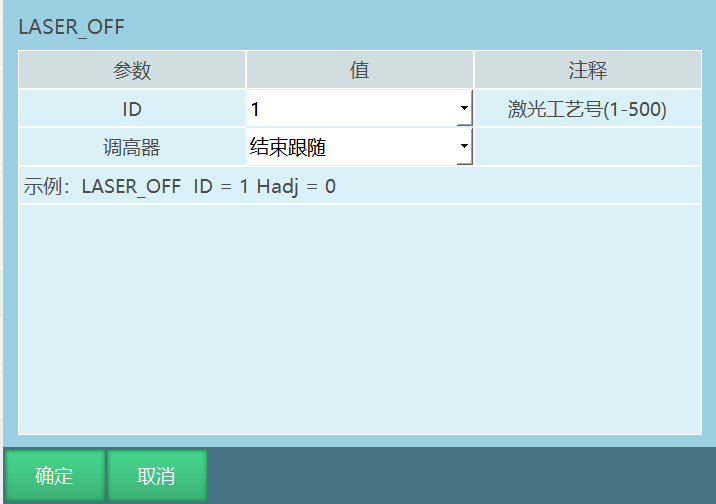
Note: The height adjuster follow option is a dev feature, not available in 2403.
Format: LASER_OFF [Instruction Name] ID=1 [Process Number] Height Adjuster=End Follow [Height Adjuster Follow Option].
Function: Stop cutting after reaching the cutting end point.
Parameters:
| ID | Laser cutting process number, range (1,500) |
|---|---|
| Height Adjuster | End Follow Height adjuster resets, stops running. |
| Height Adjuster | Continue Follow without emission Close shutter enable and air blow enable at cutting end and continuously send follow signal. Continue running after receiving the follow-in-place signal. |
Cutting Circle
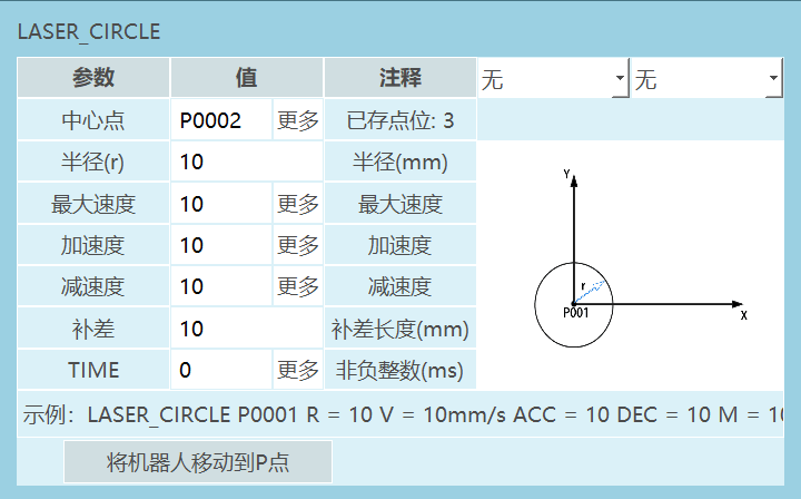
Format: LASER_CIRCLE [Instruction Name] P/GP [Center Point] R [Radius] V [Maximum Speed] ACC [Acceleration Ratio] DEC [Deceleration Ratio] M [Compensation] TIME [Early execution time, displays 0 if not set].
Function: Set cutting circle parameters. When running to this instruction, the cutting circle trajectory is executed.
Parameters are shown in the table:
| Center Point | Center point of the cutting circle trajectory. Uses local position variable (P) or global position variable (GP). |
|---|---|
| Radius (r) | Joint interpolation speed, range [1,3000] |
| Maximum Speed | Instruction speed during circle cutting, range [1,999] |
| Acceleration | Acceleration ratio during circle cutting, range [1,100] |
| Deceleration | Deceleration ratio during circle cutting, range [1,100] |
| Compensation | After the full circle is completed, continue running the circle trajectory by the compensation distance, range [0,500] |
| TIME | Early execution time, same as the early execution time of motion control instructions. It is the time for the next non-motion instruction to execute early. Unit ms |
Laser Setting
Note: The laser setting instruction is a dev feature, not available in 2403.
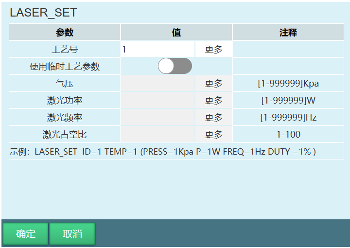
Format: LASER_SET [Instruction Name] ID [Process Number] TEMP [Whether to use temporary process parameters] (PRESS [Gas Pressure] P [Power] FREQ [Frequency] DUTY [Duty Cycle] (Temporary process parameters))
Function: This instruction can modify gas pressure, power, frequency, and duty cycle during cutting through instructions without stopping.
Parameters are shown in the table:
| Process Number | Laser cutting process number, range (1,500), range [1,500], can bind variables |
|---|---|
| Use Temporary Process Parameters | If the temporary parameter switch is not turned on, gas pressure, laser power, laser frequency, and laser duty cycle are the values set in the process parameter interface. When the temporary parameter switch is turned on, users can modify gas pressure, laser power, laser frequency, laser duty cycle, and other parameters at any time based on the environment. |
| Gas Pressure | Laser cutting gas pressure, range [1-99999] Kpa, can bind variables |
| Laser Power | Laser cutting power, range [1-99999] W, can bind variables |
| Laser Frequency | Number of laser pulses emitted per second, range [1-99999] Hz, can bind variables |
| Laser Duty Cycle | Proportion of laser output signal duty time, range [0,100]%, can bind variables |
Example:
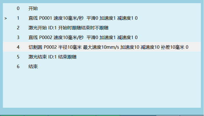
Laser instructions support linear, arc, full circle, and curve movements. Usage is relatively simple. Only cutting circle is somewhat special.
Cutting circle needs to run based on the previous point. If the previous motion instruction's point is P0001, the cutting circle's center point must also be set to P0001 to run.
AI Retrieval Q&A (Q&A for Retrieval)
Q: Still blowing air after cutting is complete
A: In the global parameters interface, change the gas shutoff mode to no shutoff.
Q: No emission during cutting
A: 1. Check if the shutter switch is open. 2. Check if cutting parameters are too low. Too low frequency cannot emit. 3. Check if IO ports are correctly set. 4. Check hardware wiring for damage. 5. Check if the laser is set to external control mode. 6. Check if the laser is reporting an alarm.