1 Introduction to the Collaborative Robot
A collaborative robot, as the name implies, emphasizes the concept of "collaboration", focusing on the collaboration between humans and robots. Based on this, ease of use, safety and intelligence are particularly important.
The original intention of the collaborative robot is to achieve human-machine collaborative work, enabling human-machine coexistence within a certain range without installing fences. Therefore, the emergence of collaborative robots has changed the production relationship and broken down the barriers between humans and machines.
First, from a commercial perspective, collaborative robots are the fastest-growing category in the industrial robot market. Their performance is superior to six-axis robots and other traditional industrial robots, and they have become the direction the market pursues. In addition, compared with traditional industrial robots, competition in the collaborative robot field is more relaxed.
Furthermore, a collaborative robot is a humanoid manipulator whose purpose is to replace the human hand. As we can see, in unattended retail fields such as coffee shops and milk tea stations, collaborative robots can not only perform simple actions such as taking cups, picking and placing materials, and pressing buttons, but can also do latte art with a high degree of consistency. The existing collaborative robot product matrix is based on human design logic, including extreme motion and dynamic design, modular hardware structure design, flexible and reliable adaptation software, multilingual combinations, etc.
2 Setting the Slave Configuration
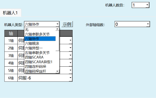
Click Settings/Robot Parameters/Slave Configuration, and select Six-Axis Collaborative Robot as the robot type.
2.1 Preset Parameters
In the DH parameter screen, we provide the preset robot function. If the drop-down list contains your robot model, you can use this function to quickly and conveniently set all robot parameters.
Click [Preset Robot] in the upper left corner of the DH parameter screen to select an already adapted robot model. After selection, the DH parameters and joint parameters of that robot are automatically filled in.

After selecting a preset robot, the zero point must be modified manually.
2.2 Setting DH Parameters
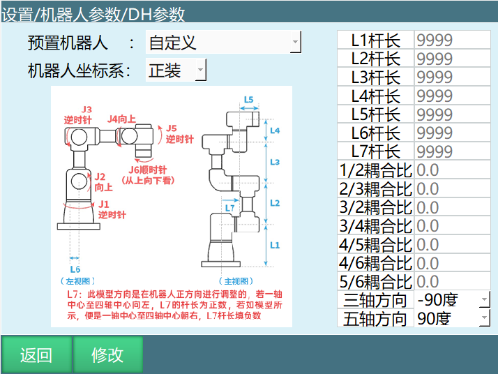
Click Settings/Robot Parameters to enter DH Parameters, and fill in parameters such as the robot link lengths, coupling ratio, and 3-axis/5-axis direction; this parameter affects the robot's linear motion and accuracy;
Note: After the DH parameters and joint parameters are set, power on and operate the robot to confirm whether the model direction is correct.
3 Six-Axis Collaboration Related Description
3.1 Parameter Description
Preset Robot
By importing the robot joint parameters and DH parameters into the controller in advance, the step of repeatedly filling in parameters can be omitted.
Robot Coordinate System
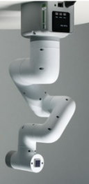
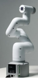
As shown in the figure, the upper one is upright and the lower one is inverted:
Note: Identification and collision detection are not supported in the inverted configuration!
Link Lengths
The control system needs to accurately model the robot in order to calculate the current coordinates of the robot end and the angles that each joint axis needs to rotate when the robot moves from point A to point B. Modeling the robot requires determining the length of each part of the robot; these lengths are the link length parameters, also called DH parameters.
The link length parameters must be filled in according to the model diagram shown in the DH page. Inaccurate filling will affect the robot motion accuracy.
Coupling Ratio
Some robot bodies are designed so that a motor spans multiple axes to drive a certain axis, which causes coupling between two axes. For example, when we operate the 2nd axis to rotate, the 3rd axis also rotates — this is axis coupling. To counteract this coupling effect, a coupling ratio is needed.
The coupling ratio calculation formula is: coupling ratio = rotation angle of the following axis / rotation angle of the main axis.
For example, if we operate the 2nd axis to rotate 10° and find that the 3rd axis follows with a rotation of 15°, then the coupling ratio is 15/10=1.5.
For the detailed calculation method of the coupling ratio, please refer to the "NRC Debugging Manual".
3-Axis/5-Axis Direction
In six-axis collaboration, the 3-axis and 5-axis directions correspond to the two configurations of the collaborative robot.
3.2 Setting Joint Parameters
The setting steps are the same as in "Robot Parameter Debugging".
Note: Do not power on and operate the robot before the DH parameters and joint parameters are set!
3.2.1 Meaning of Each Parameter
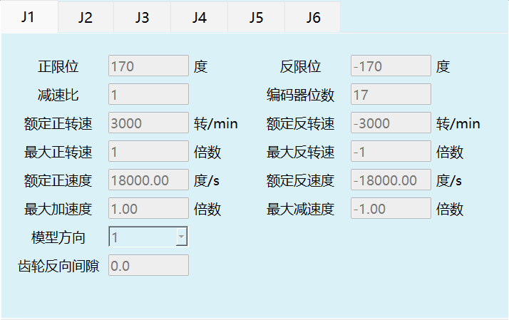
Positive limit: The maximum range of the robot joint in the positive direction.
Negative limit: The maximum range of the robot joint in the negative direction (this value must be negative).
Reduction ratio: The reduction ratio of the reducer.
Encoder bits: The number of bits of the encoder.
Rated positive speed: The rated speed of the motor in the positive direction.
Rated negative speed: The rated speed of the motor in the negative direction (this value must be negative).
Maximum positive speed: The maximum speed of the motor in the positive direction, expressed as a multiple of the rated positive speed. For example, if the rated positive speed is 3000 rpm and the maximum positive speed needs to be 6000 rpm, fill in 2x here.
Maximum negative speed: The maximum speed of the motor in the negative direction, expressed as a multiple of the rated negative speed. For example, if the rated negative speed is -4000 rpm and the maximum negative speed needs to be -6000 rpm, fill in -1.5x here (this value must be negative).
Rated positive velocity: The rated positive-direction velocity of the robot joint, automatically calculated from the rated positive speed, encoder bits and reduction ratio; no need to fill in.
Rated negative velocity: The rated negative-direction velocity of the robot joint, automatically calculated from the rated negative speed, encoder bits and reduction ratio; no need to fill in. (This value must be negative)
Maximum acceleration: The maximum acceleration of the robot joint motion, expressed as a multiple of the rated positive velocity. For example, if the rated positive velocity is 300°/s and the maximum acceleration needs to be 1500°/s², fill in 5x here.
Maximum deceleration: The maximum deceleration of the robot joint motion, expressed as a multiple of the rated negative velocity. For example, if the rated negative velocity is 300°/s and the maximum acceleration needs to be 1200°/s², fill in -4x here. It is recommended that the maximum acceleration and maximum deceleration values be the same (this value must be negative).
Model direction: The model direction is set with reference to the joint positive direction diagram below. The "+" key jog of each axis should be in the same direction as the joint positive direction diagram. Select 1 if the same, -1 if opposite.
Actual joint direction: Defaults to 1.
Gear backlash: Whenever the joint moves in the opposite direction, the filled-in angle value is compensated. Leave blank by default.
| Robot type | Axis | Positive direction (top view or left view) |
|---|---|---|
| Six-axis collaborative | J1 | Counterclockwise |
| J2 | Upward | |
| J3 | Counterclockwise | |
| J4 | Upward | |
| J5 | Counterclockwise | |
| J6 | Clockwise (viewed from top) |
Joint positive direction diagram:
Note: Do not power on and operate the robot before the joint positive direction is set.
3.3 Zero-Point Calibration
If the robot zero position is a non-standard zero position, the user can align the robot according to the alignment holes, then set the current robot position coordinates as the zero position on the robot zero position screen.
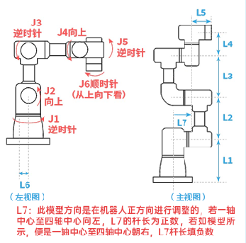
The six-axis collaborative zero position diagram is as follows (roughly the shape of this model; they are the zero models of the two configurations). For the configuration on the left, the model direction is adjusted on the left side of the robot; for the configuration on the right, the model direction is adjusted in the positive direction of the robot. If the direction from the center of axis 1 to the center of axis 4 is to the left, the L7 link length is positive; if, as shown in the figure, the direction from the center of axis 1 to the center of axis 4 is to the right, the L7 link length is negative:
Ensure the robot is at this position, then click Set All Joints to Zero.
Note: Do not power on and operate the robot before the DH parameters and joint parameters are set.
Notes
- Without origin position calibration, homing cannot be performed!
- In a system with multiple robots, every robot must be calibrated for the origin position!
- When there is a coupling relationship between joint axes, for example, the common coupling between the fifth and sixth axes of a robot, the sixth axis must be at the zero position when the fifth axis is at the zero position for the recorded sixth-axis zero data to be valid. Otherwise, the recorded sixth-axis zero data is invalid. Therefore, the sixth-axis zero data must be recorded while the fifth axis is at the zero position. If there is no coupling relationship, each axis can be calibrated independently, and each axis's zero position does not affect the zero positions of other joints.
3.4 Setting Cartesian Parameters
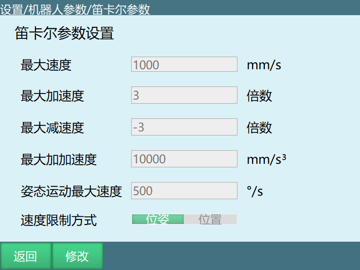
The Cartesian parameters can directly use the default values.
3.4.1 Meaning of Each Parameter
Maximum speed: The maximum linear speed of the robot during operation (all V parameters that need to be filled in inserted instructions are limited by the Cartesian parameters).
Maximum acceleration: The maximum acceleration of the robot during operation, expressed as a multiple of the maximum speed. For example, if the maximum speed is 1000 mm/s and the maximum acceleration needs to be 3000 mm/s², fill in 3x here.
Maximum deceleration: The maximum deceleration of the robot during operation, expressed as a multiple of the maximum speed. For example, if the maximum speed is 1000 mm/s and the maximum deceleration needs to be -3000 mm/s², fill in -3x here. It is recommended that the maximum acceleration and maximum deceleration values be the same, and the same as the maximum acceleration and maximum deceleration in the joint parameters (this value must be negative).
Maximum jerk: The maximum jerk is displayed on the Cartesian parameter screen only when the robot interpolation mode is jerk interpolation.
Maximum pose motion speed: The maximum speed of the robot during pose motion; instruction speeds exceeding it will be reduced.
Speed limit mode
- Pose: The robot's linear interpolation motion is limited by both the maximum speed and the maximum pose motion speed.
- Position: The robot's linear interpolation motion is limited only by the maximum speed.
4 Six-Axis Collaborative Robot Parameter Settings
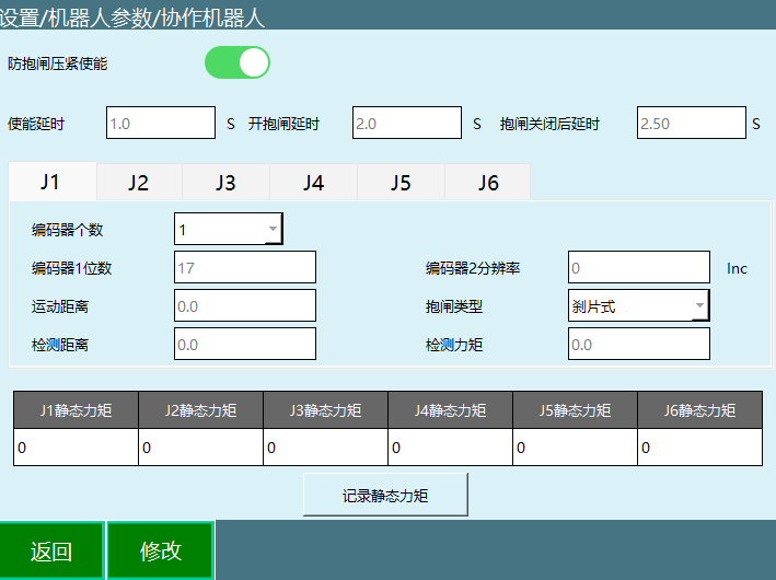
This screen is the parameter setting screen for the six-axis collaborative robot; other types of robots do not need to be set.
4.1 Detailed Usage of Collaborative Robot Parameters
Enable delay: The delay after pressing the enable key before the enable command is sent to the servo.
Brake-open delay: The delay after sending the enable command before the brake-open command is sent to the servo.
Delay after brake close: The delay after the brake is closed before the servo responds to the next operation.
Encoder count: The number of encoders in a single joint.
Encoder 1 bits: Same as the encoder bits in the joint parameters.
Encoder 2 resolution: The inc value of the other encoder in a single joint.
Motion distance: The micro-motion distance of the joint before the brake opens, generally 20.
Brake type: Disc brake and pin brake.
Detection distance: The joint motion distance used to detect whether the brake is open after the brake opens.
Detection torque: During the detection distance run after the brake opens, if the torque of the joint exceeds the detection torque, the brake is considered to have failed to open.
Q&A
Q1: How do I select a preset robot?
A: Click the "Preset Robot" drop-down list on the DH parameter screen, select an already adapted robot model, and the system automatically fills in the DH parameters and joint parameters. After selection, the zero position must be modified manually.
Q2: What are the consequences of incorrect DH parameter settings?
A: DH parameters affect the robot's linear motion and accuracy. Inaccurate filling will cause inaccurate robot motion or reduced accuracy. After setting, power on to confirm whether the model direction is correct.
Q3: How is the coupling ratio calculated?
A: Coupling ratio = rotation angle of the following axis / rotation angle of the main axis. For example, if the main axis rotates 10° and the following axis rotates 15°, the coupling ratio is 1.5. For detailed calculation, please refer to the "NRC Debugging Manual".
Q4: How is the joint positive direction set?
A: Set the model direction according to the joint positive direction diagram. If the "+" key jog of each axis is in the same direction as the diagram, select 1; if opposite, select -1. Do not power on and operate the robot before setting.
Q5: What should be noted during zero-point calibration?
A: Ensure the robot is aligned with the alignment holes and set the current position as the zero point. In a multi-robot system, each robot must be calibrated. If joints are coupled, other axes must be calibrated while the coupled axis is at the zero position.
Q6: Can the Cartesian parameter default values be used directly?
A: Yes, the Cartesian parameters can directly use the default values, including the maximum speed, acceleration, etc. It is recommended that the maximum acceleration and deceleration values be the same.
Q7: What is the enable delay in the collaborative robot parameters?
A: The enable delay is the delay after pressing the enable key before the enable command is sent to the servo, used to ensure system stability.
Q8: What brake types are there?
A: The brake types include disc brake and pin brake. Select the corresponding type according to the robot model.
Q9: What should I do if the brake fails to open?
A: Check the detection distance and detection torque settings. If the torque exceeds the detection torque, the opening is considered failed. Adjust the parameters or check the hardware connections; if necessary, contact technical support.