External Axis User Manual
| Instruction Type | Foreground | Global Background | Local Background |
|---|---|---|---|
| External Axis Point-to-Point | Supported | ||
| External Axis Linear | Supported | ||
| External Axis Arc | Supported | ||
| External Curve | Supported |
External Axis Introduction
External axes refer to axes added in addition to the robot body for work requirements, such as ground rails, tilting tables, and rotating tables. They are used in industries such as spraying, welding, and cutting.
External Axis Types
- Linear Single Axis
Mount the robot on a ground rail and use the external axis function to control the ground rail sliding to achieve long-distance movement of the robot in a single direction, enabling large-range, multi-station work.
- Linear Dual Axis
Mount the robot on a ground rail and use the external axis function to control the ground rail sliding to achieve simultaneous long-distance movement of the robot in two directions, enabling larger-range, multi-station work.
- Linear Triple Axis
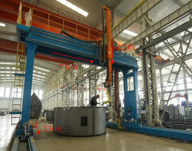
Mount the robot on a ground rail and use the external axis function to control the ground rail sliding to achieve simultaneous long-distance movement of the robot in three directions, enabling even larger-range, multi-station work. The installation structure is shown in the figure:
- Rotating Single Axis
Can be divided into: tilting axis or rotating axis
Tilting axis: The tilting table is independent of the robot body. Through the external axis function, the tilting table can be controlled to tilt to a specific angle, which is more conducive to processing a certain face of the workpiece. It is mainly used in welding, cutting, spraying, etc. For example, in the spraying industry, the tilting table can be tilted to spray the upper and lower surfaces of the workpiece.
Rotating axis: The rotating table is independent of the robot body. Through the external axis function, the rotating axis is controlled, and during welding operations, the workpiece is welded as the external axis rotates.
- Rotating Dual Axis
Combines the rotating axis and tilting axis for use.
External Axis Configuration
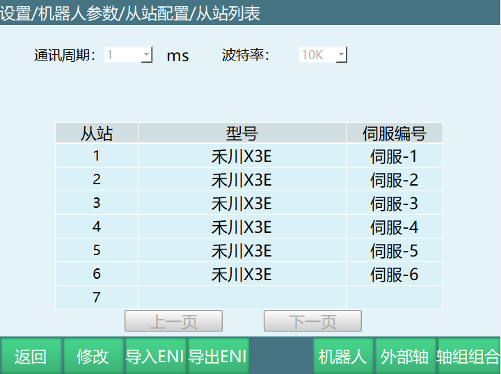
- Click Settings - Robot Parameters - Slave Configuration to enter the slave list interface, then click [External Axis] on this interface to enter the external axis configuration interface.
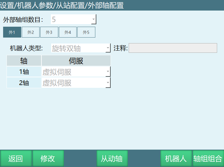
External Axis Group Count: Maximum support for 12 groups, equivalent to external axis numbers.
Click [Modify] to set the external axis group count.
After setting the external axis group count, click the corresponding external axis number to set the robot type.
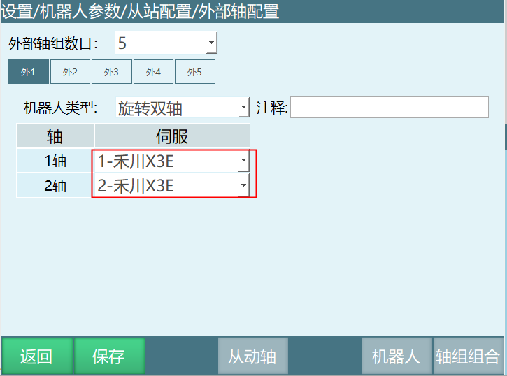
After setting the parameters in the external axis configuration interface, click [Save].
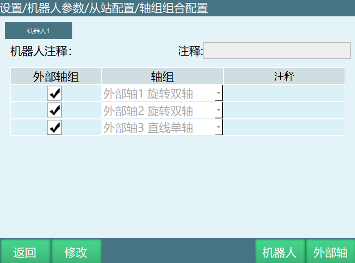
Click [Axis Group Combination] to enter the axis group combination configuration interface.
After completing the parameter settings, click Save. The external axis configuration is complete.
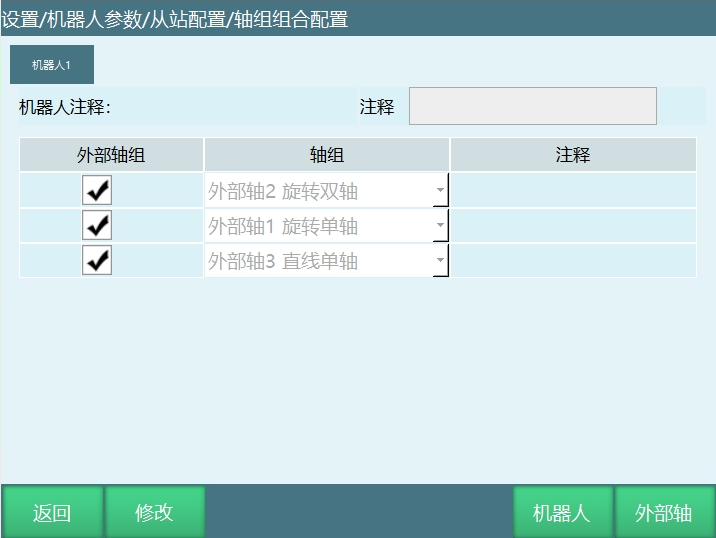
External Axis Group: Supports up to three external axis groups. Click the corresponding row to select the external axis group.
Axis Group: The axis group column parameters can only be selected after selecting the external axis. The parameters displayed in this column are the external axis number + robot type set in the external axis configuration interface. Users select different axis group combinations based on the set parameters.
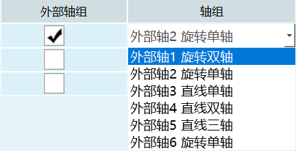
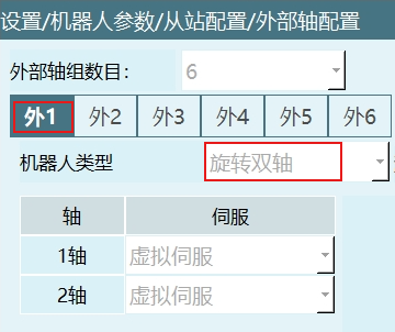

External axis groups only support 3 groups; The total number of external axes only supports 5.
Example
- On the slave configuration page, confirm whether the servo used by the external axis has been detected. If detected, the slave page will display it, as shown:
- On the external axis configuration page, select the servo according to the corresponding axis.
- On the axis group combination page, select the external axis group.
External Axis Calibration
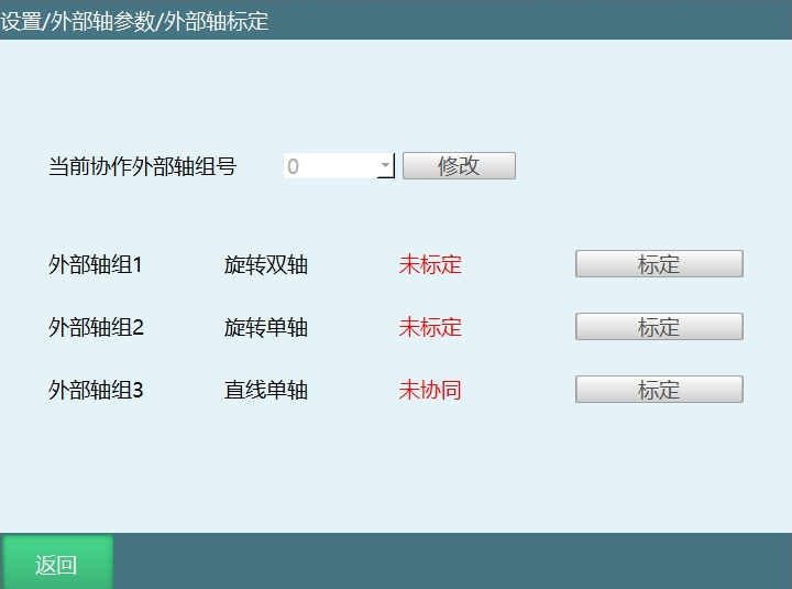
After the external axis is connected successfully, external axis calibration can be performed.
Current Collaborative External Axis Group Number: Range 1-3. When the external axis type is rotating single axis or rotating dual axis, the collaborative group number needs to be set; otherwise, external axis linear and arc instructions cannot run. When the external axis type is a linear axis, the collaborative group number does not need to be selected.
Calibration: Click the calibration button of the corresponding external axis group to enter the calibration interface.
Rotating Dual Axis Calibration
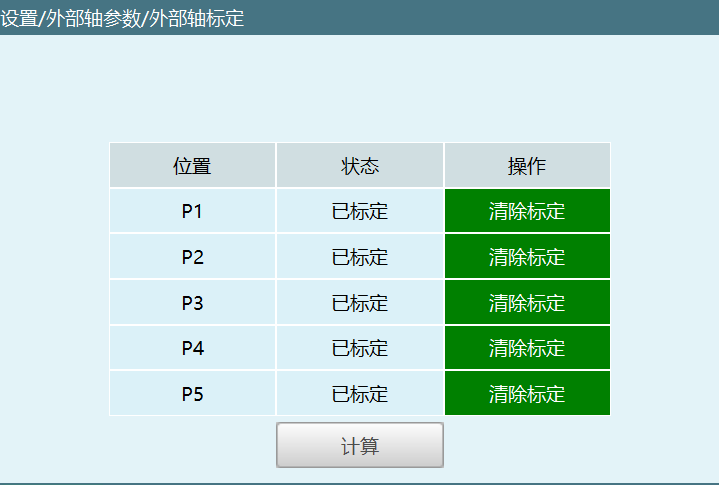
The external axis calibration interface is shown in the figure.
Calibration Steps:
Return the external axis to zero point, and find a point on the rotating table as reference point A;
P1: Rotate external axis 2 in the positive direction by about 100 degrees. At this time, reference point A is at P1. Move the robot tip to P1 and click calibrate;
P2: Rotate external axis 2 in the negative direction by about 50 degrees. At this time, reference point A is at P2. Move the robot tip to P2 and click calibrate;
P3: Return the external axis to zero. At this time, reference point A is at P3. Move the robot tip to P3 and calibrate P3;
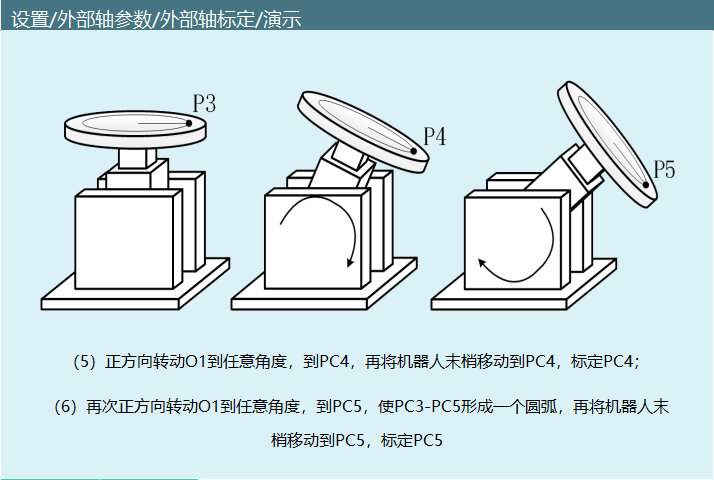
P4: Rotate external axis 1 in the positive direction by about 25 degrees. At this time, reference point A is at P4. Move the robot tip to P4 and click calibrate;
P5: Rotate external axis 1 in the positive direction again by about 25 degrees. At this time, reference point A is at P5. Move the robot tip to P5 and click calibrate;
Click calculate.
Rotating Single Axis Calibration
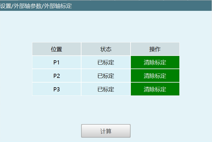
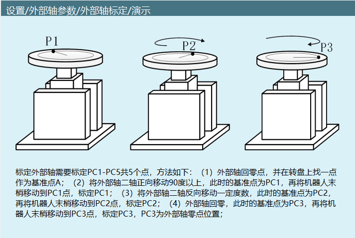
Return the external axis to zero point, and find a point on the platform as reference point A;
Rotate the external axis in the positive direction by 100 degrees. At this time, A is at P1. Move the robot tip to P1 and calibrate P1;
Rotate the external axis in the negative direction by 50 degrees. At this time, A is at P2. Move the robot tip to P2 and calibrate P2;
Return the external axis to zero. At this time, A is at P3. Move the robot tip to P3 and calibrate P3;
Click calculate.
Tilting Single Axis Calibration
Return the external axis to zero point, and find a point on the platform as reference point A;
Rotate the external axis in the positive direction by 50 degrees. At this time, A is at P1. Move the robot tip to P1 and calibrate P1;
Rotate the external axis in the negative direction by 25 degrees. At this time, A is at P2. Move the robot tip to P2 and calibrate P2;
Return the external axis to zero. At this time, A is at P3. Move the robot tip to P3 and calibrate P3;
Click calculate.
Linear Single Axis Calibration
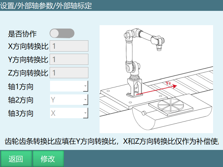
- X-direction conversion ratio: The distance the linear single axis moves in the X direction when the reducer output shaft rotates one revolution.
Calculation method 1: First fill in the conversion ratio value as 1, then measure the distance the linear single axis travels in the X direction when the reducer output shaft rotates one revolution, and re-enter the measured value as the conversion ratio;
Calculation method 2: Distance the linear single axis travels in the X direction (number of teeth * tooth pitch), and re-enter the calculated value as the conversion ratio;
- Y-direction conversion ratio: The distance the linear single axis moves in the Y direction when the reducer output shaft rotates one revolution.
Omitted, calculation method can refer to [X-direction conversion ratio].
- Z-direction conversion ratio: The distance the linear single axis moves in the Z direction when the reducer output shaft rotates one revolution.
Omitted, calculation method can refer to [X-direction conversion ratio].
Axis direction: The movement direction of the linear single axis: X, Y, Z three directions, only one can be selected.
When the axis direction is selected and the conversion ratio is modified, opening the collaborative enable switch is considered as calibrated.
Linear Dual Axis Calibration
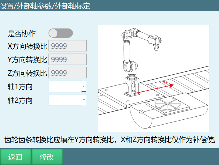
Omitted, refer to linear single axis calibration.
Note: Axis direction: The movement direction of the linear dual axis: X, Y, Z three directions, only two can be selected, and they cannot be repeated.
Linear Triple Axis Calibration
Omitted, refer to linear single axis calibration.
Note: Axis direction: The movement direction of the linear triple axis: X, Y, Z three directions, all are required selections.
Direction Calibration
Due to installation errors when installing the ground rail and robot, there may be deviations between the ground rail direction and the robot's Cartesian coordinate system direction. This can be corrected through the direction calibration using the ratio coefficients calculated from calibration.
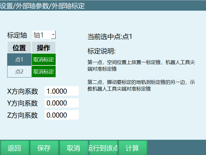
This function can only be used when [Collaborative] mode is selected.
Calibrate the first point of axis 1: Place a calibration cone in the spatial position, and align the robot tool tip with the calibration cone.
Calibrate the second point of axis 1: Move the ground rail to be calibrated to the other end of the calibration cone, and align the robot tool tip with the calibration cone.
Click [Calculate] to calculate the ratio coefficients for X, Y, Z directions.
Click [Save].
Note: Linear single axis requires calibrating one axis, linear dual axis requires calibrating two axes, and linear triple axis requires calibrating all three axes.
Zero Point Position
Zero Point Calibration
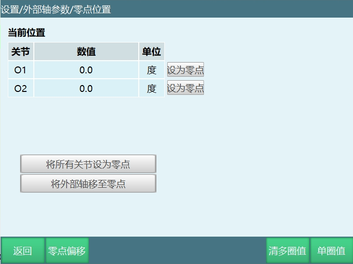
The zero point position setting is shown in the figure.
The zero point is the position where all external axis positions are zero. Users can set the external axis zero point position themselves.
Set as Zero Point: Set the position of a selected axis as the zero point.
Set All Joints as Zero Point: Set the positions of all external axes as zero points.
Move External Axis to Zero Point: In teach mode, enable the servo, click [Move External Axis to Zero Point], and the external axis moves to the zero point position.
Zero Point Offset
Zero point offset can be used when the user needs to adjust the zero point. Enter values manually. The operation method is similar to zero point calibration.
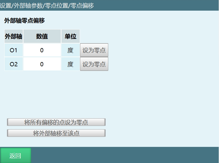
The zero point offset setting options are shown in the figure.
Set as Zero Point: Adjust the zero point position of a specific external axis. Select the external axis whose zero point position needs to be adjusted, enter the value manually, click [Set as Zero Point], then click [Return] on this interface to enter the zero point position interface, and click [Set as Zero Point] for the corresponding axis to modify the zero point position.
Set All Offset Points as Zero Point: Adjust the zero point positions of all external axes. Enter values manually, click [Set All Offset Points as Zero Point], then click [Return] on this interface to enter the zero point position interface, and click [Set All Joints as Zero Point] to modify all zero point positions.
Move External Axis to This Point: In teach mode, enable the servo, click [Move External Axis to This Point], and the external axis moves to the zero point position.
Clear Multi-Turn Value
Multi-turn value is the number of revolutions of the servo motor.
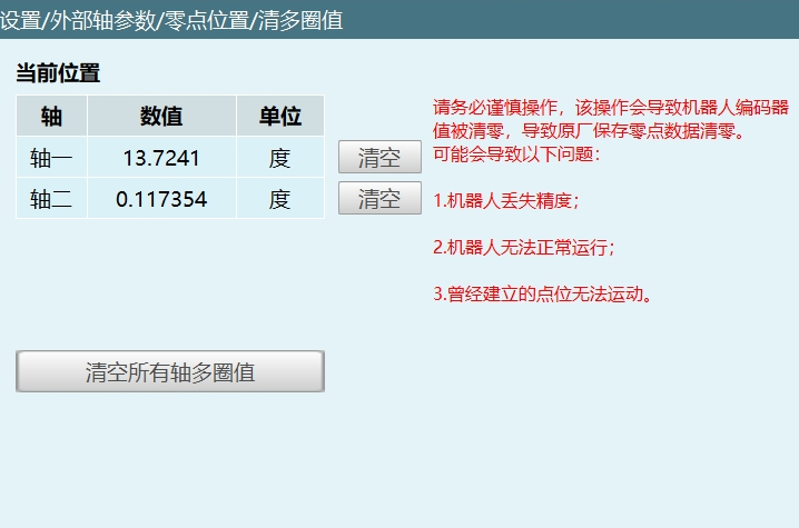
As shown in the figure, the clear multi-turn value interface has several options. The explanations are as follows:
Clear: Clear the multi-turn value of a specific external axis.
Clear All Axis Multi-Turn Values: Clear the multi-turn values of all external axes.
 Operation Warning Please operate with extreme caution! This operation will cause the robot encoder values to be cleared, which will also clear the zero point data saved by the manufacturer. Possible Problems: - Robot loses precision - Robot cannot operate normally - Previously established points cannot be executed |
|---|
Single-Turn Value
Single-turn value is the number of pulses obtained within one revolution based on resolution and rotation angle.
After modifying the single-turn value, clicking save will modify the angle value.
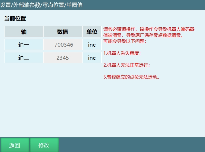
Please operate with extreme caution. This operation will cause the robot encoder values to be cleared, which will also clear the zero point data saved by the manufacturer!
Possible problems:
- Robot loses precision;
- Robot cannot operate normally;
- Previously established points cannot be executed.
External Axis Parameters
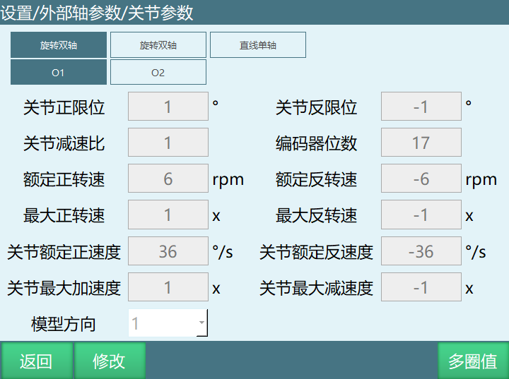
Joint Positive Limit: The angle or distance the robot rotates or moves in the positive direction. Exceeding the limit during motion will cause an error (robot jog position reaches limit).
Joint Negative Limit: The angle or distance the robot rotates or moves in the negative direction. Exceeding the limit during motion will cause an error (robot jog position reaches limit).
Joint Reduction Ratio: The reduction ratio of the reducer.
Encoder Bits: Fill in the number of encoder bits currently in use. Be careful not to fill in randomly, otherwise the robot may experience runaway during jogging.
Rated Positive Speed: The speed at which the motor can operate in the positive direction.
Rated Negative Speed: The speed at which the motor can operate in the negative direction.
Maximum Positive Speed: For example, at 1x, the time from 0 speed to rated positive speed is 10 seconds, so at 2x it takes 5 seconds to reach rated positive speed.
Maximum Negative Speed: For example, at 1x, the time from 0 speed to rated negative speed is 10 seconds, so at 2x it takes 5 seconds to reach rated negative speed.
Joint Rated Positive Speed: The rated positive direction speed of the robot joint. Calculation method: Rated positive speed * 360 / 60 / reduction ratio.
Joint Rated Negative Speed: The rated negative direction speed of the robot joint. Calculation method: Rated negative speed * 360 / 60 / reduction ratio.
Maximum Acceleration: For example, at 1x, the time from 0 speed to maximum acceleration is 10 seconds, so at 2x it takes 5 seconds to reach maximum acceleration.
Maximum Deceleration: For example, at 1x, the time from 0 speed to maximum deceleration is 10 seconds, so at 2x it takes 5 seconds to reach maximum deceleration.
Model Direction: The model direction can be set according to the joint positive direction diagram in the zero point position interface. The "+" key for jogging each axis should match the direction shown in the joint positive direction diagram. Select 1 if the same, -1 if opposite.
Multi-Turn Value
Click [Settings] - [External Axis Parameters] - [Joint Parameters] to enter the joint parameter interface, then click [Multi-Turn Value] to modify the encoder range.
Encoder Multi-Turn Value Overflow Counting Function: This function is used to eliminate the impact of jumps between the encoder's maximum/minimum values.
For example, if the encoder multi-turn value range is [-2147483648, 2147483647] and the current encoder multi-turn value position is 2147483647, then rotating one more unit in the positive direction would result in -2147483648. If the system does not know the encoder multi-turn value range, it would think the robot suddenly jumped and would not know that it actually only rotated one unit, which could easily lead to a runaway situation.
| This parameter must be filled in. Not filling it may cause the following problems: 1. Large jumps in position, for example suddenly changing from 4 degrees to 40 degrees 2. Runaway Special Note: If configuring a slave axis, the encoder maximum/minimum values of the slave axis must also be filled in! |
|---|
Jog Speed
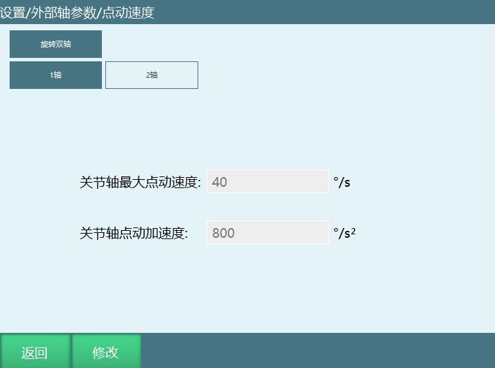
As shown in the figure is the jog speed interface. The terms are explained as follows:
Joint Axis Maximum Jog Speed: The speed when jogging the external axis. When the external axis is a rotating axis, the unit is °/s; when the external axis is a linear axis, the unit is mm/s.
External Axis Jog Speed Calculation Method: Joint axis maximum jog speed * global speed (the global speed here refers to the speed in the status bar at the top of the teach pendant).

Joint Axis Jog Acceleration: Omitted.
External Axis Instructions
When modifying the speed of external axis instructions, the acceleration ratio and deceleration ratio will automatically display in a 1:1 ratio with the speed. If you need to modify the acceleration ratio or deceleration ratio, you can do so manually.
External Axis Point-to-Point
Function: The robot moves to the taught position using joint interpolation. When the external axis rotates, the robot moves on the external axis through the taught points.
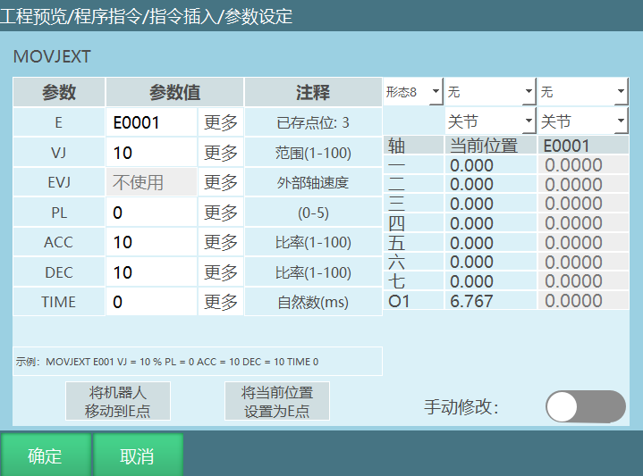
| Parameter | Name | Description | Range / Default |
|---|---|---|---|
| E | Position Variable | Records the position data of the robot and external axis. When the value is "New", inserting this instruction creates a new E variable and records the current positions of the robot and external axis into this E variable. | - |
| VJ | Joint Speed | The speed of joint interpolation. | [1,100] |
| EVJ | External Axis Speed | The speed ratio of the external axis motion. Adding this parameter is to increase the overall running speed. The speed that takes longer to run is used for calculation. When set to [Not Used], when the robot and external axis move simultaneously, one of them may move very slowly. | [1,100] |
| PL | Smoothing Level | The smoothness of trajectory transition. Higher values are smoother. | [0,5] |
| ACC | Acceleration | Acceleration change rate. | [1,100] |
| DEC | Deceleration | Deceleration change rate. | [1,100] |
| TIME | Pre-execution Time | The time to read and execute the next instruction in advance. | Unit: ms |
Move Robot to E/GE Point: In teach mode, press the enable button, click [Move Robot to E/GE Point], and the robot and external axis will move to the position of the currently selected variable.
Set Current Position as E/GE Point:
Write the current positions of the external axis and robot into the selected variable.
If the current position is a joint position, the current joint position coordinates will be written into the target variable;
If the current position is a Cartesian position, the current Cartesian position coordinates will be written into the target variable;
If the current position is a tool position, the current tool position coordinates will be written into the target variable;
If the current position is a user position, the current user position coordinates will be written into the target variable.Manual Modification: Open the manual modification button, and the user can manually modify the position.
Example:
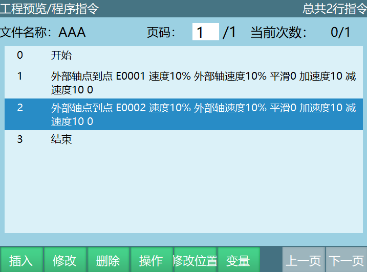
Example: The robot moves from E0001 to E0002, and the external axis rotates during the E0001-E0002 motion.
External Axis Linear
Function: The robot moves to the taught position using linear interpolation. When the external axis rotates, the robot moves in a linear trajectory on the external axis.
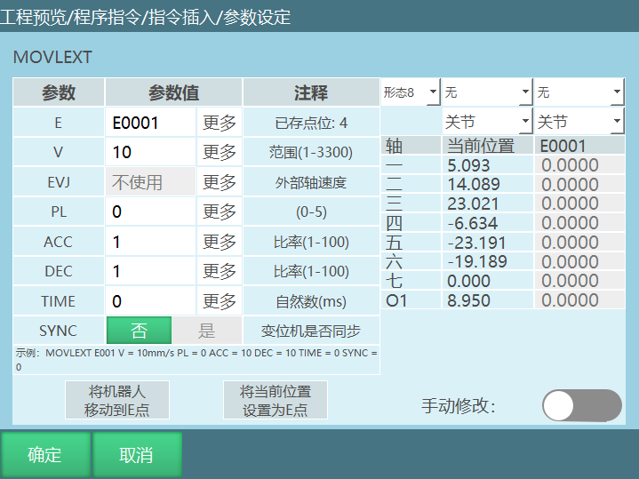
| Parameter | Name | Description | Range / Default |
|---|---|---|---|
| E | Position Variable | Records the position data of the robot and external axis. Select New: Creates a new variable when inserting the instruction and records the current position. | - |
| V | Linear Speed | The speed of the robot's linear interpolation. | 1 - 1000 (mm/s) (Limited by Cartesian parameter maximum speed) |
| EVJ | External Axis Speed | The speed ratio of the external axis motion. | [1, 100] |
| PL | Smoothing Level | The smoothness of trajectory transition. Higher values are smoother. | [0, 5] |
| ACC | Acceleration | Acceleration change rate. | [1, 100] |
| DEC | Deceleration | Deceleration change rate. | [1, 100] |
| TIME | Pre-execution Time | The time to read and execute the next instruction in advance. | Unit: ms |
| SYNC | Synchronization Mode | Controls the coordination between the robot and external axis. On: Collaborative linear motion (robot and external axis synchronized). Off: Robot moves linearly, external axis moves independently to the target angle. | ON / OFF |
Move Robot to E/GE Point: In teach mode, press the enable button, click [Move Robot to E/GE Point], and the robot and external axis will move to the position of the currently selected variable.
Set Current Position as E/GE Point:
Write the current positions of the external axis and robot into the selected variable.
If the current position is a joint position, the current joint position coordinates will be written into the target variable;
If the current position is a Cartesian position, the current Cartesian position coordinates will be written into the target variable;
If the current position is a tool position, the current tool position coordinates will be written into the target variable;
If the current position is a user position, the current user position coordinates will be written into the target variable.Manual Modification: Open the manual modification button, and the user can manually modify the position.
Note: Before using the external axis linear instruction, you must select the external axis group number in the external axis calibration interface, otherwise the program will report an error during runtime. The external axis must be accurately calibrated, otherwise there will be synchronization issues between the robot and external axis when executing the external axis linear instruction.
Example:
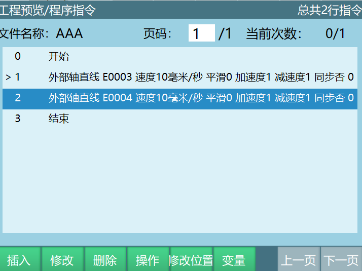
Example: After the robot reaches E0003, the robot and external axis collaboratively move in a linear trajectory to E0004.
External Axis Arc
Function: The robot and external axis move together. The robot moves to the taught position using arc interpolation, and the external axis moves using joint interpolation.
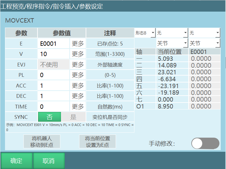
The parameter setting interface is shown in the figure:
| Parameter | Name | Description | Range / Default |
|---|---|---|---|
| E | Position Variable | Records the position data of the robot and external axis. Select New: Creates a new variable when inserting the instruction and records the current position. | - |
| V | Linear Speed | The speed of the robot's linear interpolation. | 1 - 1000 (mm/s) (Limited by Cartesian parameter maximum speed) |
| EVJ | External Axis Speed | The speed ratio of the external axis motion. | [1, 100] |
| PL | Smoothing Level | The smoothness of trajectory transition. Higher values are smoother. | [0, 5] |
| ACC | Acceleration | Acceleration change rate. | [1, 100] |
| DEC | Deceleration | Deceleration change rate. | [1, 100] |
| Pre-execution Time | Pre-execution Time | The time to read and execute the next instruction in advance. | Unit: ms |
| SYNC | Synchronization Mode | Controls the coordination between the robot and external axis. On: Collaborative curve motion (robot and external axis synchronized). Off: Robot moves in a curve, external axis moves independently to the target position. | ON / OFF |
Move Robot to E/GE Point: In teach mode, press the enable button, click [Move Robot to E/GE Point], and the robot and external axis will move to the position of the currently selected variable.
Set Current Position as E/GE Point: Write the current positions of the external axis and robot into the selected variable. If the current position is a joint position, the current joint position coordinates will be written into the target variable; if the current position is a Cartesian position, the current Cartesian position coordinates will be written into the target variable; if the current position is a tool position, the current tool position coordinates will be written into the target variable; if the current position is a user position, the current user position coordinates will be written into the target variable.
Manual Modification: Open the manual modification button, and the user can manually modify the position.
Note: Before using the external axis arc instruction, you must select the external axis group number in the external axis calibration interface, otherwise the program will report an error during runtime. The external axis must be accurately calibrated, otherwise there will be synchronization issues between the robot and external axis when executing the external axis arc instruction.
Example:
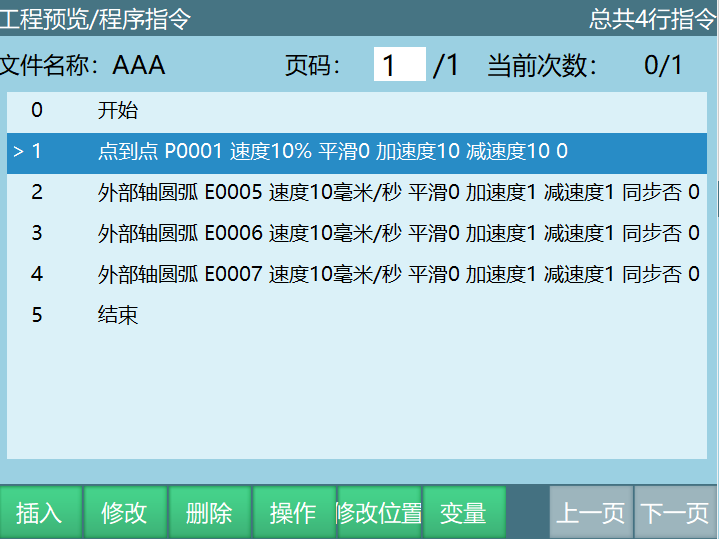
Example: The robot moves from the current position to P0001, then from P0001 to the arc start point E0005. After reaching E0005, it moves to the arc midpoint E0006, and completes the entire external axis arc trajectory at E0007. During the E0005-E0007 motion, the robot and external axis collaboratively move in an arc. As the robot moves to the taught target point, the external axis also rotates synchronously.
External Axis Curve
Function Overview: The robot moves to the taught position using curve interpolation, while the external axis moves synchronously using curve interpolation.
- The robot end-effector moves along the taught curve trajectory (e.g., from
E0002toE0005). - During the curve trajectory, the external axis (such as a positioner or turntable) rotates synchronously.
The parameter setting interface is shown in the figure:
| Parameter | Name | Description | Range / Default |
|---|---|---|---|
| E | Position Variable | Records the position data of the robot and external axis. Select New: Creates a new variable when inserting the instruction and records the current position. | - |
| V | Linear Speed | The speed of the robot's linear interpolation. | 1 - 1000 (mm/s) (Note: Limited by Cartesian parameter maximum speed) |
| EVJ | External Axis Speed | The speed ratio of the external axis motion. | [1, 100] |
| PL | Smoothing Level | The smoothness of trajectory transition. Higher values are smoother. | [0, 5] |
| ACC | Acceleration | Acceleration change rate. | [1, 100] |
| DEC | Deceleration | Deceleration change rate. | [1, 100] |
| Pre-execution Time | Pre-execution Time | The time to read and execute the next instruction in advance. | Unit: ms |
| SYNC | Synchronization Mode | Controls the coordination between the robot and external axis. On: Collaborative curve motion (robot and external axis synchronized). Off: Robot moves in a curve, external axis moves independently to the target position. | ON / OFF |
Notes:
External Axis Group Selection Before using the external axis curve instruction, you must select the corresponding external axis group number in the external axis calibration interface.
Calibration Accuracy The external axis must be accurately calibrated. If the calibration is inaccurate, synchronization between the robot and external axis will have deviations when executing the external axis curve instruction, leading to trajectory errors.
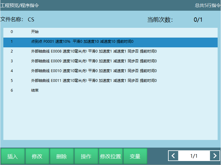
Example: The robot moves from the current position to P0001, then from P0001 to the curve start point E0008. After reaching E0008, it moves to the curve transition point E0009, and completes the entire external axis curve trajectory at E0011. During the E0008-E0011 motion, the robot and external axis collaboratively move in a curve. As the robot moves to the taught target point, the external axis also rotates synchronously.
External Axis Notes
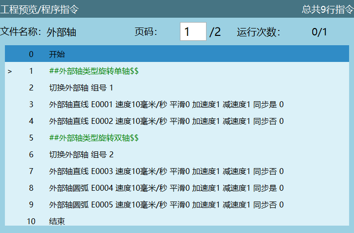
- When setting multiple external axes, the robot can only collaborate with one external axis group at a time. You can switch the current collaborative external axis group by inserting the collaborative external axis instruction, as shown below:
External axis linear and arc instructions cannot enable synchronized operation when the external axis is not calibrated or the collaborative group number is not selected.
When the external axis type is linear single axis, linear dual axis, or linear triple axis, the collaborative external axis group number does not need to be selected.
Using External Axes
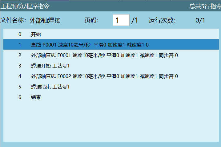
In welding processes, the external axis of a welding robot mainly assists the robot in completing welding actions while improving efficiency and precision. The robot and positioner perform coordinated motion. After the robot completes welding on one side, the positioner automatically flips to the other side for welding operations.
Operation Steps:
External axis calibration, set external axis parameters;
Set welding parameters in the welding process interface;
Teach points (welding trajectory).
Welding